INJECTOR HEAD GRIPPERS FOR CABLE IN OIL-WELL APPLICATIONS AND METHOD
US20260117606A1
2026-04-30
19/365,409
2025-10-22
Smart Summary: Grippers have been created to hold and move armored power cables used in oil wells. They apply just the right amount of pressure to avoid damaging the cable's protective layers and internal parts. This design helps install electrical submersible pumps more quickly and reliably. The grippers fit onto the injector head chain and grip the cable tightly, allowing safe movement in and out of the well. Additionally, rollers are included to guide the cable smoothly from the reel to the injector head. 🚀 TL;DR
Abstract:
Configurations for grippers designed for holding and moving armored power cables for downhole well operations are provided. The grippers are designed to ensure a certain amount of compression force can be exerted against the cable without damaging the armor strands, the internal electrical core including power conductors, insulation or the metallic shielding of the same. Improved installation speed and reliability for electrical submersible pumps may be realized through the system and methods disclosed herein. An armored cable matching coiled tubing injector head grippers are installed on the injector head chain and are compressed against the cable creating the necessary frictional force to safely convey the cable and the attached ESP in and out of the well. Another aspect is a set of rollers fitted to the cable guide attached to the injector head to safely guide the cable from and to the cable reel.
Applicant:
Interested in similar patents?
Get notified when new applications in this technology area are published.
Classification:
E21B19/08 » CPC main
Handling rods, casings, tubes or the like outside the borehole, e.g. in the derrick; Apparatus for feeding the rods or cables Apparatus for feeding the rods or cables ; Apparatus for increasing or decreasing the pressure on the drilling tool; Apparatus for counterbalancing the weight of the rods
Description
CROSS-REFERENCE TO RELATED APPLICATION
This application claims the benefit of priority to U.S. provisional application 63/713,264, filed on Oct. 29, 2024. This prior application is incorporated herein by reference.
FIELD
The technology disclosed herein relates to a device for gripping a cable in an oil-well application, in particular for gripping a cable for an electrical submersible pump for use in a wellbore.
BACKGROUND
Electrical submersible pump (ESP) systems are a type of artificial lift system used in oil and gas wells to increase the flow of fluids (such as water and/or oil) to the surface. An ESP generally includes a pump that is submerged in the wellbore and is powered by a downhole electric motor. The ESP system is designed to operate under high temperatures, pressures, and corrosive conditions, making it suitable for use in harsh downhole environments.
ESPs may be installed in a wellbore with a landing assembly. An ESP is electrically connected to an external power source at the top of the wellbore via an electrical power cable. Near the top of the wellbore on the spool there are a set of electrical connectors configured to contact electrical connectors at the ESP cable hanger leading to an external power source. These electrical connectors should be lined up with a matching set of electrical connectors on the outer ring of the surface spool situated below the Christmas tree.
Installing, replacing, or repairing an ESP requires significant time and cost in preparing the wellbore to perform the installation or change out operation, lasting days and even weeks at times. Among the many operations needed are “killing the well,” consisting of pumping heavy fluids in the well to prevent uncontrolled well fluids spill at surface, and the spudding of a workover rig to remove the complete production assembly at the end of which the ESP is connected. Often the preparation for servicing the ESP or removing the landing equipment involves even more time than the time to replace or repair the ESP. Landing assembly equipment and personnel time is also valuable, so a fast and accurate system and method for installing, electrically connecting the ESP, and releasing the landing equipment is desirable.
In order to convey a cable-deployed ESP system in an oil well, some form of surface conveyance unit is needed for the cable. The cable includes electrical wiring and thus has a certain fragility that is not present in most downhole applications. A reel can be used to move the cable up or down, but this is not optimum for many situations. In addition, after the cable is removed from the reel, another method of holding the cable in place is required. The cable may be deployed in well depths exceeding 10,000 ft, such as 11,000 to 20,000 feet, or 12,000 to 15,000 ft, and surface tension loads of 0 to 35,000 lbs, such as 1,000 to 20,000 lbs, or 5,000 lbs to 12,000 lbs. Gripping and holding the cable in place requires high levels of compression and friction. When cable armors are under high loads, not only do they compress, but they also twist slightly. Devices in contact with holding the cable outer armor will prevent such natural twisting, thereby potentially causing a cable armor twist-off. This presents a problem especially for very long and heavy cable deployments, as the compression forces required to hold the cable in place can damage the cable.
While chain-driven gripper systems exist for coiled tubing, these have not been implemented with the types of armored, powered cables used with ESP systems. Such conventional systems also do not have grippers configured for use with armored, powered cables. Coiled tubing is simple and robust. High amounts of frictional force (e.g., 40,000 to 100,000 lbs) can be used without concern for damaging delicate parts, and even if the tubing is partially crushed or damaged it is typically not catastrophic. Armored cable is much easier to compress and damage. Larger, heavier armored cables for ESP systems would be desirable in many applications because they are needed to provide sufficient power for higher horsepower pumps. Conventional grippers may be flat, V-shaped, and/or have some contour for tubing (but not with high side walls and near 360-degree coverage). Conventional grippers are not configured to reliably handle the compressible, armored power cables disclosed herein without damaging them.
SUMMARY
The following is a brief summary of subject matter that is described in greater detail herein. This summary is not intended to be limiting as to the scope of the claims.
Improvements in ESP installation speed and reliability may be realized without the use of a workover rig or the need to kill the well. Further improvements can be achieved by using the power cable itself to deploy and retrieve the ESP in the well. An exemplary operation entails the use of a coiled tubing injector head fitted with cable-sized matching grippers that clamp on the cable in sets of pairs mounted on opposing chains. A set (e.g., set comprising seven to twelve pairs) of grippers can be mounted on the opposing chains, depending on the pulling capacity of the injector head. Such gripper pairs are hydraulically pressed against the cable, making contact and exerting an upwards or downwards frictional force on the cable when the chains are moved. The cable and the attached ESP can then be lowered or retrieved from the well safely.
In another aspect, the injector head grippers compression force can be controlled to ensure no damage to the cable outer surface armors or the electrical core, without causing cable slippage “runaway” when friction forces are insufficient. In an exemplary operation, gripper traction hydraulic pressures can be pre-set from the injector head control unit to prevent cable slippage with the increasing tension as the cable is deployed in the well. Damage may be determined by any breakage of any part of the armor strands or internal core, including insulation or shielding membranes, or cable armor twisting under high torque associated with high tension in wireline style cables.
In another aspect, cable size specific guide rollers are installed on the guide or “gooseneck” attached to the injector head on the cable reel side of the injector head, with the purpose to bend gently the vertically well-exiting cable and guide it towards the cable reel situated on the coiled tubing unit located on the ground.
In another aspect, the guide rollers roll with the cable movement and reduce any frictional forces created by the bending of the cable over a given surface.
In some aspects, the techniques described herein relate to modifications to injector head grippers for installing an electrical submersible pump system in a wellbore. For example, one set of grippers mounted in pairs on opposing drive chains, one set of roller guides mounted on the injector head guide or goose neck to help guide the cable vertically exiting the well situated one hundred feet or more above the well onto a cable reel mounted on a coiled tubing unit spudded on the ground level. A set of hydraulic pressure settings can be used to ensure the gripper traction force does not damage the cable while moving it in and out of the well with an amount of required force to ensure safe lowering or retrieving the cable and the attached ESP without cable damage or slippage within the injector head.
In another aspect, one pair of the above grippers herein is mounted inside a mechanical clamping device with the objective to secure cable when cutting and terminating the cable section protruding outside the well, after the ESP has reached its installation depth and stabbed into the production packer. This safety device is required to hold the cable and the ESP weights in the well indefinitely and without the risk of cable slipping and falling into the well.
In a different aspect, a curved cable guide or gooseneck is attached to the injector head with the main purpose to guide the vertically upwards injector head exiting cable situated over 100 ft in the air above the well, and towards the cable reel situated on the coiled tubing unit located on the ground level or the main platform level on an offshore rig or platform situation. The guide is fitted with multiple rollers of similar size to the cable, and are used to reduce the curvature friction between the cable and the guide by supporting the weight and tension of the cable and rotating freely at the same time as the cable is moved, and preventing the cable to come in contact with the surface of the guide that can lead to cable and guide wear and damage. The rollers need to be of same size or slightly larger than the cable size and can be procured from industry standard rollers.
In another aspect the roller guides can be manufactured to fit the cable size and installed on the guide to minimize cable damage during continuous movement in and out of the well.
In some aspects, the techniques described herein relate to a set of grippers for an armored cable including multiple armor strands including: a first gripper and second gripper, each having a concave inner contact profile configured to match an outer diameter profile of the armored cable; the first gripper and second gripper include a trough that is adjacent to first and second surrounding walls; the first and second gripper are configured to compress a section of the armored cable and to cover at least 330 degrees of an outer diameter of the section of the armored cable.
In some aspects, the techniques described herein relate to a system for holding or moving an armored cable with multiple armor strands in a downhole application, the system including: an injector head with a first set of chain-driven grippers and an opposing second set of chain-driven grippers; the first set of chain-driven grippers and second set of chain-driven grippers compressing the armored cable, wherein each of the first set of chain-driven grippers and second set of chain-driven grippers have a concave inner contact profile configured to match an outer diameter profile of the armored cable; the first set of chain-driven grippers and second set of chain-driven grippers include a trough that is adjacent to first and second surrounding walls; the first set of chain-driven grippers and second set of chain-driven grippers are configured to compress at least a section of the armored cable and to cover at least 330 degrees of an outer diameter of the section of the armored cable.
In some aspects, the techniques described herein relate to a method for driving an armored cable in a downhole application, the method including the steps of: loading the armored cable into an injector head; adjusting injector head compression pressure for a first and second set of chain-driven grippers to hold and move the armored cable without slippage; driving the armored cable to move from a reel to a wellhead or the wellhead to the reel by moving the first and second set of chain-driven grippers; wherein there is no damage to the armored cable outer surface or the electrical core.
The above summary presents a simplified summary in order to provide a basic understanding of some aspects of the systems and/or methods discussed herein. This summary is not an extensive overview of the systems and/or methods discussed herein. It is not intended to identify key/critical elements or to delineate the scope of such systems and/or methods. Its sole purpose is to present some concepts in a simplified form as a prelude to the more detailed description that is presented later.
BRIEF DESCRIPTION OF THE DRAWINGS
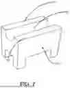
FIG. 1 is a side plan view of an exemplary system for installing a cable deployed ESP system.
FIG. 2 is a side plan view of an exemplary ESP system in a wellbore deployed at the end of the production tubing.
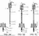
FIGS. 3A to 3C are side plan views of an exemplary cable deployed system including the ESP and other downhole components of the wellhead as they are installed into the wellbore.
FIG. 4 is a cut-away view of an exemplary armored cable.
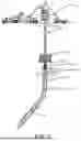
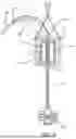
FIG. 5 is a schematic view of an exemplary injector head, cable guide, and blow-off preventer.
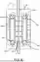
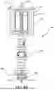
FIG. 6 is a schematic view of an exemplary injector drive section.
FIG. 7 is a perspective view of an exemplary gripper.
FIG. 8A is a schematic view of an exemplary system including an injector head and cable clamp.
FIG. 8B is a schematic view of an exemplary system utilizing the cable clamp in the field.
FIGS. 9A and 9B are photographs of the prototype gripper pair mounted in a test fixture where various test loads were applied on either side of the cable.
FIG. 9C is a photograph of the larger test frame without the grippers but with the cable section installed.
FIG. 10 is graph showing cable tension increase (y-axis) over time (x-axis) with the slippage events and increased gripper force identified in callouts on the graph.
FIG. 11A is a photograph of the armored cable after testing.
FIG. 11B is a photograph of the armored cable power conductor core after testing.
FIG. 12 is a Finite Element Analysis (FEA) image of the armored cable.
FIG. 13A is a plot showing the test results of different types of grippers on the one size cable at different tension increase and decrease points.
FIG. 13B is a plot showing further pull testing test results of different types of grippers.
FIG. 14 is a flowchart showing an example method of use of exemplary systems and devices disclosed herein.
It should be noted that the drawings are not to scale.
DETAILED DESCRIPTION
Various technologies pertaining to electrical submersible pumps (ESPs) and load bearing power cable movement in and out of the oilwell are now described with reference to the drawings, wherein like reference numerals are used to refer to like elements throughout. In the following description, for purposes of explanation, numerous specific details are set forth in order to provide a thorough understanding of one or more aspects. It may be evident, however, that such aspect(s) may be practiced without these specific details. In other instances, known structures and devices are shown in block diagram form in order to facilitate describing one or more aspects. Further, it is to be understood that functionality that is described as being carried out by certain system components may be performed by multiple components. Similarly, for instance, a component may be configured to perform functionality that is described as being carried out by multiple components.
Moreover, the term “or” is intended to mean an inclusive “or” rather than an exclusive “or.” That is, unless specified otherwise, or clear from the context, the phrase “X employs A or B” is intended to mean any of the natural inclusive permutations. That is, the phrase “X employs A or B” is satisfied by any of the following instances: X employs A; X employs B; or X employs both A and B. In addition, the articles “a” and “an” as used in this application and the appended claims should generally be construed to mean “one or more” unless specified otherwise or clear from the context to be directed to a singular form. Additionally, as used herein, the term “exemplary” is intended to mean serving as an illustration or example of something, and is not intended to indicate a preference. In addition, the terms “inner” and “outer” are in reference to the longest axis of the devices and systems disclosed herein. The term “fluidly coupled” means a fluid, such as oil, can flow through from one end of the area it relates to, to another. For example, X is fluidly coupled to Y, means fluid can flow through tubing or some channel or chamber from X to Y or vice versa.
Typically, a cable for ESP system is mounted on a reel and a winch system that can move the cable and any attached loads (assembly) downhole in the well and also retrieve the assembly. The traction force needs to meet and exceed the weight of the assembly and drag forces and any other movement opposing forces that may apply to the assembly in the well. The forces applied to the cable at surface both moving down or up in the well are highest at the deepest point of installation in the well. In addition, the cable traction mechanism needs to safely apply overpull to the system in order to disconnect the power cable from the ESP in the event of stuck ESP situation. In an embodiment, the same traction mechanism at the surface should be adequate to reliably complete multiple installations and retrievals of the cable ESP system from the well without damaging the cable.
Typically, wireline cables are wound on a wireline drum, which in turn is installed in a winch system (hydraulic or electrical or a combination), itself mounted at the back of truck chassis, or a flat bed unit or an offshore skid. The winch is controlled by a drive system mounted inside a cabin usually located immediately behind the wireline drum. Conventional wireline winches can accommodate and pull typical wireline cables of diameter not exceeding 0.5 inches. For purpose applications, cable diameters can be pushed to 0.8 inches and apply a pull tension of not exceeding 18,000 lbs. Any stronger and cables that need pulls higher than 18,000 lbs would require a specially designed and expensive winch system, e.g., one equipped with a capstan or tension multiplier, to accommodate such size and weight. To the inventor's knowledge, such equipment does not even exist for cable sizes larger than 0.5 inches. In certain applications it would be desirable to have larger cables for powering higher horsepower pumps. For example, the systems disclosed herein can power a pump with 100 HP or more, e.g., 130 HP to 250 HP, or 150 HP to 230 HP. In an embodiment, the cable and systems disclosed herein allow for pumps in suitable wells to produce 5,000 to 10,000 barrels/day (e.g., crude petroleum output).
Alternatively, for high tension and large diameter cables a commercial coiled tubing unit and injector head can be used to deploy and retrieve such cables. A coiled tubing injector head consists of two opposing chains mounted with special grippers or tracks that are pressed against a coiled tubing and can move hydraulically the coiled tubing in and out of the well by frictional forces applied to the coiled tubing itself. Wireline cables on the other hand have stranded armor wires and are not designed to withstand compression from standard coiled tubing grippers. Damage is highly likely to occur.
Fit for purpose coiled tubing injector head grippers need to be designed and tested with the cable prior to committing to an actual deployment of wireline type cables in well depths exceeding 10,000 ft and tension loads exceeding 25,000 lbs or even higher loads, such as 35,000 lbs for future applications. Disclosed herein is the design and testing of such grippers on a given size cable, including an initial Finite Element Analysis (FEA) to prove the cable will be able to handle compression while moving in and out of the well without damage. Utilizing this approach, a coiled tubing unit can be used for the cable deployed ESP system. This approach also can eliminate the need to have very large size sheave wheels, needed for a typical wireline operation. Finally, this design prevents the bending and spooling of a large size cable under high tensions (cable crushing or insulation cold flow damage), which is known to-damage wireline cable and drums.
With reference to FIG. 1, an exemplary cable-deployed ESP system in a wellbore 5 with landing equipment is depicted in a schematic view. The ESP 1 is already deployed into the wellbore 5 adjacent to a pre-installed packer 15. In this example a crane hoists an injector head 10 and pressure control equipment 12 above the wellbore 5. The pressure control equipment 12 is connected to the injector head 10. One or more risers 20 are coupled to the pressure control equipment 12. Inside the risers 20 are additional components of the technology disclosed more fully in FIGS. 6 to 10E. The risers 20 are connected to a blow-out preventer 25 (BOP) which is coupled to a Christmas tree unit 30. The Christmas tree unit 30 is coupled to cable hanger and spool components 35. A variable speed drive (VSD) 40 is coupled to the wellbore 5 for pumping fluid from the well. Lengths of risers are variable and the drawings are not drawn to scale.
Above the pressure control unit 12 there is an injector head 10 where two opposing gripper chains are mounted. (See further details in FIG. 5 and description thereof.) The mentioned chains can move forward and backwards towards the cable based on hydraulic pressures applied to a motor mounted moving mechanism. Such action is utilized when installing and removing cable from the injector head. This movement also allows the installation or removal of the grippers connected to the chain in an evenly distributed pattern.
The ESP 1 is coupled to a cable 45 that runs through the wellbore 5, through the hanger and spool components 35, the Christmas tree unit 30, the risers 20, the BOP 25 and the pressure control equipment 12 to a reel 50. The reel 50 contains the coiled cable 45. In operation the cable can be advanced (downhole) or retracted (uphole) by a feeding mechanism. In this example, the feeding mechanism (the injector head) is a set of conveyor belts that contact two sides of the cable 45 to drive it downhole or uphole.
An electrical power source (not shown) provides power to the VSD 40 and to the ESP 1 via the cable 45. Connections in the hanger and spool components 35 couple the power source to the electrical core wiring in the cable 45. The power source may, for example, drive current at 120 Amps at 5000 volts (or larger amperage for other versions of cable, e.g., up to 240 Amps or 360 Amps).
In this example, the cable 45 is a heavy-duty hybrid cable that includes a 3 conductor electrical core, and is surrounded by load bearing double layered metal armors for protection and heavy-duty load bearing. In other embodiments, the electrical core may include multiple conductors or a single conductor.
The load bearing double layer armor is made of stainless steel or other alloy metallurgy. The cable 45 can have an outer diameter, of, for example, 0.5 to 2 inches, such as 0.85 to 1.25 inches, or 1 to 1.25 inches, or 1.25 inches to 1.5 inches. The cable 45 may have a tensile strength of at least 25,000 lbs, e.g., 30,000 to 45,000 lbs, or 40,000 to 65,000 lbs, and may run in lengths of, for example, 2,000 to 15,000 ft, or 5,000 to 10,000 ft, or 7,000 feet.
In ESP wellbore systems that employ heavy duty cabling that includes power cabling inside it for the ESP, additional challenges are presented. Cable damage can occur if the injector head forces cable down while the ESP is not moving (e.g., stuck or already landed), or is caught on some wellhead component and cannot move down.
The ESP is described in more detail in FIG. 2, which shows an exemplary ESP 110 disposed within the walls of a wellbore 49. The system 100 includes an ESP 110, which comprises a pump 120, a motor protection component 130, and a motor component 140. A power connector 150 is also shown at the top of the motor component 140. The power connector 150 is attached to a power conduit cable 160, which runs up the side of the ESP 110 and continues up to the top of the wellbore 49 where it is coupled to an external power source. In other embodiments, other configurations of the various components of the ESP may also be used.
In an embodiment, the motor component 140 is at a bottom end of the ESP 110 and a top end of the motor component 140 is coupled to a bottom end of the motor protection component 130. A top end of the motor protection component 130 is coupled to the pump 120. In an embodiment the ESP 110 used in the cable deployed systems is an inverted Permanent Magnet Motor (PMM) ESO, where the pump is at the bottom with a bottom inlet and mid-section discharge, and the motor is above the pump.
An intake opening 125 is on the side of the pump 120 near the bottom end of the pump 120. Fluid from the wellbore 49 comes into the ESP from this intake opening 125 and is pumped through the pump 120 up and out of the wellbore 49 via the production tubing 170.
FIGS. 3A-3C show the system including the ESP 301 and other downhole components of the wellhead 327 and method as they are installed into the wellbore. In FIG. 3A, the cable 345 is advanced through the injector head 310 and through the risers 320. The risers 320, pressure control equipment (also known as a stripper) 399, and injector head 310 are disconnected from the rest of the wellhead 327 to allow for the installation of the downhole components. The ESP 301 and other downhole components are then installed at the end of the cable 345 and the cable 345 and ESP 301 are retracted up into the risers 320. A crane moves the risers 320 over the wellhead 327 which is closed to wellbore fluids. The bottom terminal end of the risers 320 is then locked into place onto the top of the blow out preventer (BOP) 325. (See FIG. 3B.) Then, after a safety pressure test to confirm no leaks, the wellhead sealing valve is opened and the cable 345 is advanced downhole and the ESP 301 and other downhole equipment is lowered into the wellbore through the opened Christmas tree unit 330. (See FIG. 3C.) The ESP 301 may be lowered up to 20,000 ft, e.g., 2,000 to 15,000 ft, or 5,000 to 8,000 ft.
Inside the injector head 310 there are a pair of opposing chain-driven sets of grippers for moving the cable 345. A set of 8-12 opposing pairs of grippers clamp onto the cable 345 and help move the cable 345 up and down as the chain-driven grippers are hydraulically driven up and down. In other embodiments, the set may comprise 6 to 50, or 10 to 25, or 14 to 20 opposing pairs of grippers. These grippers provide tremendous force on the lateral sides of the cable.
The pressure control equipment 399 is connected immediately below the injector head 310. Pressure control equipment 399 is typically used for coiled tubing deployment with a smooth outer surface. Stranded armor power cables 345 however have armor strands at the outer surface and require viscous grease injection at the pack-off level to ensure continuous pressure seal against wellbore fluids during the cable movement in or out of the well. Grease is typically injected at 20% higher than the encountered wellhead pressure. The pressure control equipment 399 contains one or more packoff elements (e.g., one, two, or three packoff elements) that are used to contact the cable outer armor where grease is injected to control well fluid pressures around the cable 345 as it moves in and out of the well. The packoff elements may be used to hold back fluids in the wellbore from, e.g., 0 to 10,000 pounds per square inch (psi). The cable 345 is allowed to move freely inside the pressure control equipment 399 in any direction with constant pressure viscous grease injection at the gauge or similar point.
The pack-off consists of a rubber element of the same diameter as the cable 345 inserted in the packing window around the cable and providing dynamic seal around the cable 345 assisted by grease injection to enable the cable 345 to move freely with ease. The internal diameter of the pack-offs needs to maintain a very small gap to the cable 345 outer diameter.
FIG. 4 is a cut-away view of an armored cable 400. In this example, the armored cable 400 is a heavy-duty hybrid cable that includes a 3 conductor electrical core, and is surrounded by load-bearing double-layered multiple armor strands 420 for protection and heavy-duty load bearing. In an embodiment, the armored cable 400 has an electrical core (first, second, and third electrically conductive wires 421, 422, 423) and is protected by a double layered, and helically wound metallic armor (multiple armor strands 420). In an embodiment, the armored cable 400 has at least two layers and the inner and outer layer are wound in an opposite helical manner. The armor strands 420 of the armored cable 400 provide the mechanical strength to enable the complete assembly to be installed and retrieved from the well. In an embodiment, the armored power cable disclosed herein may be classified as a wireline type cable, and is not a coiled tubing. Therefore, the cable is more flexible, and ductile and cannot be pushed in a well in the same manner as coiled tubing without damage. In an embodiment, the power cable has an average diameter of 1″ or larger, e.g., 1.25″ to 3″, or 1.5″ to 2″.
The multiple armor strands 420 may be made of stainless steel or other alloy metallurgy. The multiple armored strands 420 may, e.g., be made of cylindrical wire, or be made of other geometrical shape of gauge ranging 0.075 inches to 0.15 inches diameter (measured at the largest diameter if the strand is not cylindrical). There may be, e.g., 16 to 100 armored strands, such as, e.g., 20 to 80, or 30 to 60 armored strands. The armored cable 400 can have an outer diameter, of, for example, 0.5 to 2 inches, such as 1.1 to 1.25 inches, or 1.15 to 1.5 inches. The armored cable 400 may have a tensile strength of at least 20,000 lbs, e.g., 24,000 to 65,000, or 25,000 to 45,000 lbs, or 28,000 to 35,000 lbs, and may run in lengths of, for example, 2,000 to 20,000 ft, or 5,000 to 10,000 ft, or 7,000 feet.
In this embodiment, first, second, and third electrically conductive wires 421, 422, 423 are disposed inside the multiple armor strands 420 of the armored cable 400. The first, second, and third electrically conductive wires 421, 422, 423 may, e.g., be made of cylindrical wire, of gauge ranging 1 AWG (American Wire Gauge) to 6 AWG diameter, such as 2 AWG to 5 AWG, or 3 AWG to 4 AWG. The wire is a conductive metal, e.g., copper, galvanized stainless steel (for non-H2S applications), or Inconel, e.g., Inconel 825 with high Cr and Ni content for H2S concentrations exceeding 15%. In some embodiments instead of three wires there may be, multiple or a single conducting wires, e.g., 1 to 30 electrically conductive wire strands, such as, 2 to 20, or 4 to 15 electrically conductive wire strands. While not illustrated, in an embodiment, the first, second, and third electrically conductive wires 421, 422, 423 are coated with an insulation layer, e.g., an insulation layer capable of or rated for insulating up to 5,000 volts, to prevent short-circuits. In an embodiment, a conductor metallic shield (e.g. Monel tube) is also present on each first, second, and third electrically conductive wire 421, 422, 423, this layer may be on top of the insulation layer. The conductor shield is used to create a seal from well fluids that enter inside the armored cable 400 from spaces in-between the multiple armor strands 420. There is open space between the outer multiple armor strands 420 and the electrical core wires. This presents additional fragility allowing the electrically conductive wires 421, 422, 423 to move around within an interior of the armored cable 400 and against each other and the multiple armor strands 420.
FIG. 5 is a schematic view of an example injector head 510 with an injector drive section 511 that comprises a first set of chain-driven grippers 512 and an opposing second set of chain-driven grippers 514. An armored cable 545 is supported by the cable guide 505 as it enters into the injector head 510, and passes through the first set of chain-driver grippers 512 and second set of chain-driven grippers 514. The armored cable 545 then passes out of the injector head 510 and into the pressure control equipment (stripper) 12, risers 20, and blow out preventer 525.
To enable driving heavy armored cable 545 without causing damage, each gripper 515 on the first or second sets of grippers 512, 514 has a profile to match the curvature of the outer diameter of the armored cable 545 to be used. These grippers 515 can be configured to be quickly replaceable and configured to be installed on commercial coiled tubing chain drive injector heads.
In an embodiment, the grippers 515 are positioned to face each other and clamp on the armored cable 545 to provide an even compression force that will create a radial friction to prevent cable slippage and damage to the armored cable 545 at compression strength of 100 psi to 1200 psi, such as 300 psi to 1000 psi, or 400 psi to 750 psi. With a properly dimensioned gripper profile matching the armored cable, such compression strengths can hold the armored cable 545 without slippage at a single gripper pair loads of 0 lbs to 20,000 lbs, 2,000 lbs to 10,000 lbs, such as 3,000 lbs to 8,000 lbs, and 5,000 lbs to 7,000 lbs. For any given injector head may be, e.g., 8-12 sets of grippers that clamp on the cable simultaneously, thereby increasing the traction forces to, e.g., 25,000-45,000 lbs, depending on the surface load requirement. In an embodiment, the compression strength is adjusted to be in a range of the minimum required to hold the armored cable 545 without slippage and no more than 100 psi over the minimum, such as no more than 50 psi, or no more than 10 psi over the minimum.
FIG. 6 is a schematic view of an example injector drive section 611 with a first set of chain driven grippers 612 and a second set of chain-driven grippers 614. An armored cable 645 is depicted as being gripped and held in place or driven by the first set of chain driven grippers 612 and second set of chain-driven grippers 614. As can be seen, the first set of chain driven grippers 612 and second set of chain-driven grippers 614 are configured to receive the cylindrical armored cable 645 with a gripper gap 618 that is a very small distance between the outer face of the opposing grippers of the first set of chain-driven grippers 612 and second set of chain-driven grippers 614. Accordingly, the first set and second sets of chain driven grippers 612, 614 compress the cable 645 to a certain degree, e.g., the diameter of the armored cable 645 may be compressed by 0.1 to 12%, such as 1% to 10%, or 2% to 5%. The gripper depth and placement should be carefully configured to effectuate this compression so that the armored cable 645 is not damaged with too much or uneven compression and that the armored cable 645 is not held so loosely that slippage occurs.
Associated with the depth of the first and second set of chain driven grippers 612, 614 is the gripper gap 618. The first and second set of chain driven grippers 612, 614 should be configured so that the gripper gap 618 between the first and second set of chain driven grippers 612, 614, are, for example, 0 to 0.15 inches, e.g., 0.01 to 0.075 inches or 0.02 to 0.05 inches. The grippers 612, 614 should not come in contact during operation. The gripper gap 618 can be adjusted by having a greater depth, e.g., extending concave side walls of both the first and second set of chain driven grippers 612, 614 to extend to just below half the diameter of the armored cable 645.
In an embodiment, the gripper gap 618 should be no wider than the smallest or average diameter of any armored strand used in the armored cable 645. This is because armored strands, when compressed unevenly, can be pushed out away from the central long axis of the armored cable 645. If an armored strand gets pushed-out/extruded from the gripper gap 618, then serious and complex problems can result, including destruction of the armored cable 645, leading to severe delays in valuable uptime operations.
In an embodiment, the first and second set of chain driven grippers 612, 614 are configured to have a matching profile to the curvature of the armored cable 645 at its expected load range, which may influence its maximum longitudinal stretch. In an embodiment, the longitudinal length (also considered axial or vertical length when installed) of each gripper 612, 614 may be, for example, 2 to 6 inches, such as 3 to 5 inches, or 2.5 to 4.5 inches. In an embodiment, a total contact surface area of each gripper 612, 614 may be, for example, 2 in2 to 25 in2, such as, e.g., 3 to 12 in2 or 4 to 10 in2. In an embodiment, the total number of each gripper 612, 614 contacting the armored power cable 645 at one time may be, for example, 6 to 40, such as, e.g., 8 to 30, or 12 to 24.
Computer modelling can assist in configuring the first and second set of chain driven grippers 612, 614 to be properly configured for a certain armored cable 645 to prevent slippage and damage. Because of the ductile nature of the armored cable 645, it may shrink in diameter and slightly change curvature with different loads. Higher loads may require additional compressive strength to prevent slippage. In an embodiment, tests can be run at different armored cable 645 diameters and weight loads, and these can be used to calibrate and construct models for configuring appropriate matching geometry and depth of the first and second set of chain driven grippers 612, 614. Such testing was performed to design the presently described systems and methods, and at least part of this testing is disclosed in the Examples below. For all these reasons, utilizing grippers in an injector head assembly for an armored cable 645 is much more challenging than with simple tubing and was unexpectedly successful.
In operation, first and second chains 632, 634 are rotated using a gearing system coupled to a hydraulic system controlled by an injector head control unit. It should be noted that movement of the two chains is not necessarily synchronous, which further indicates a need for a proper close fit and a correct amount of compression force. The gearing system includes a first and second moving gears 642, 644 that can be rotated in both directions (clockwise and counter-clockwise) to create the chain movement to move the armored cable 645 in or out of the well and exert the traction force needed to lift the weight of the armored cable 645 and its cargo (e.g. an ESP) in the well.
FIG. 7 shows a prototype gripper 710 with an approximately concave inner surface configured to match an outer diameter profile of armored cable 645. In an embodiment, the gripper 710 has a smooth and approximately concave and semi-circular inner contact profile (inner surface). In an embodiment, the prototype gripper 710 has a trough 783 that is approximately symmetrically curved around an axis. The trough 783 is adjacent to first and second surrounding walls 781, 785 that match the profile of an armored cable 645. When pressed against the armored cable 645, the opposing pair of grippers 710 will exert a complete or near complete circle around and evenly distributed compression force on the armored cable 645. In an embodiment, the opposing pair of grippers 710 covers at least 330 degrees of at least a section of an outer diameter of the armored cable 645, such as 345 to 359 degrees, or 350 to 358 degrees. In an embodiment, an opposing pair of grippers 710 when opposed and compressed together form a complete cylindrical inner surface. In an embodiment, the pair of opposing grippers is configured to exert an approximately equal force on each of the multiple strands of armor in the armored cable they are configured to match. A gap between the pair of opposing grippers 710 at the terminal end of the surrounding walls 781, 785 of no more than a smallest outer diameter of a strand of the multiple armor strands. In an embodiment, the gap between terminal edges of the surrounding walls 781, 785 of the pair of grippers 710 will be less than 0.15 inches or less as disclosed above. The term “approximately,” as used herein can mean a deviation of no more than 2% and still contacting each of the multiple strands of armor.
The configuration of the pair of opposing grippers promotes lack of slippage of the armored cable 645 components such as the outer or inner armor strands or the electrical core. Without a tight fit profile, the components will tend to move in the direction of least resistance where no contact exists between the gripper 710 face and the armored cable 645. A poor/loose profile fit can damage the armored cable 645 externally or internally.
The gripper 710 may be made of a suitable material for durably gripping the metal strands of the armored cable without damaging it, for example, the gripper 710 is made of cast carbon steel, cast steel, or cast or forged iron or steel. In an embodiment, the gripper 710 is made of the same material as the armored strands of the armored cable.
In an embodiment, the gripper 710 has fitments on its sides and/or rear face (e.g., through-holes for pins) that are configured to fit existing commercial coiled tubing injector heads (e.g., Hydra-Rig S type chains) without the need to modify the coiled tubing injector head hardware wise or change operational controls/procedures. In this embodiment, the gripper 710 can be fit onto fit-for-purpose deployment devices using operational procedures and mechanisms similar, but not limited to, injector head-type chain driving apparatus and or fit-for-purpose coiled tubing units designed specifically for cable deployed ESP's.
Referring back to FIG. 5, it also shows a cable guide 505 (which might be referred as a “goose neck”) attached to the injector head 510. The main purpose of the cable guide 505 is to guide the armored cable 545 safely from the injector head 510 exit position located high above the ground, e.g., 100 ft or more, to direct it towards the coiled cable reel 50 (FIG. 1), located on the ground level. In an embodiment, the cable guide 505 comprises first and second guide rollers 577, 579 that have a continuous concave surface that is of the same size or slightly larger than an outer diameter of the armored cable 545 and help change the cable movement angle from vertical upwards at the injector head 510 to a more horizontal alignment directed towards the cable reel 50 (FIG. 1).
The first guide rollers 577 run along the length of the cable guide 505 on the bottom or when in vertical alignment the near side of the reel 50 (FIG. 1). The second guide rollers 579 are on a vertical or nearly vertical portion of the cable guide 505, and are opposite the first guide rollers 577 and further from the reel 50 (FIG. 1) (far side of the reel 50 (FIG. 1)). The first and second guide rollers 577, 579 have a symmetrical wheel rim-like structure with a trough in the middle and surrounding walls on the exterior edge for receiving the armored cable 545 (these form the continuous concave surface) and rolling as it progresses along its path of travel into or out of the injector head 510 and into or onto the reel 50 (FIG. 1). In an embodiment, only the first guide rollers 577 are used.
In an embodiment, the first and second guide rollers 577, 579 can be of existing sizes designed for coiled tubing type operations or in another embodiment, the first and second rollers 577, 579 can be designed specifically to fit the cable used for the ESP deployment, e.g., they can be specifically configured with a trough and surrounding walls that match the outer diameter profile of the armored cable. In an embodiment, the first and second rollers 577, 579 can have a trough and surrounding walls that are slightly larger geometry as the armored cable and/or the trough and surrounding walls of the first and second set of chain driven grippers 612, 614.
FIG. 8A is a schematic view of a system 806 similar to that described in FIG. 5. In this system a cable clamp 808 is utilized. Example injector head 810 includes an injector drive section 811 that comprises a first gripper 812 and second gripper 814. An armored cable 845 enters into the injector head 810, and passes through the first set of chain-driver grippers 812 and second set of chain-driven grippers 814. The armored cable 845 then passes out of the injector head 810 and into the pressure control equipment 826. In this embodiment, a pair of first and second grippers 812, 814 are combined in a clamp frame 890 and used as a cable clamp to secure the armored cable 845 above the well surface. More advanced pneumatic or hydraulic clamp systems can also be used with the first and second grippers 812, 814. The clamp frame may, for example, be a pair of backing plates with threaded bolts therethrough, secured and tightened by threaded nuts. The cable clamp 808 can be used for testing weights or while working on a cable termination installation as shown in FIG. 8B.
FIG. 8B is a schematic showing the cable clamp 808 being employed while working on a cable termination installation. In an embodiment, the cable clamp 808 may be applied just prior to the armored cable 845 being cut to hold it above the wellhead for service. In an embodiment, the cable clamp 808 is a backup for other methods and devices of holding the armored cable 845 in place, such as the rams of the blow-off preventer.
While methods of operation are also discussed above, FIG. 14 is flowchart succinctly showing an exemplary process of use of the systems and devices disclosed herein in a downhole application.
FIG. 14 is directed to a method for driving an armored cable in a downhole application. The method begins at step 1410, where an operator or machinery loads the armored cable into an injector head. At step 1420, the operator, or a computer can adjust the injector head compression pressure for a first and second set of chain-driven grippers to hold and move the armored cable without slippage. If removing the armored cable from the wellbore, once the terminal end of the armored cable is loaded into the injection head, the full weight of the armored cable and its cargo and resistance will immediately be manifest on the grippers, and a high compression strength will be needed to hold and move the armored cable. If the method begins by driving the armored cable into the wellbore, the maximum load at the end of the installation must be calculated and more pressure than necessary may be applied at the beginning of the retrieval procedure to achieve the required compression pressure for holding and moving the armored cable upwards at the end of the insertion process or the beginning of ESP retrieval.
At step 1430, machinery in the injector head drives the armored cable to move it from a reel to a wellhead, or (vice-versa) the wellhead to the reel by moving the armored cable with the first and second set of chain-driven grippers. In the process, there is no damage to the armored cable outer surface or the electrical core.
The grippers operating traction forces are optimized to prevent cable breakage or damage can occur in the event of excessive pulls applied to the cable. In one exemplary application, the traction forces settings are adjusted to induce cable slippage when a certain predetermined tension has reached.
EXAMPLES
Example 1
A prototype pair of grippers was designed to match the geometry of a 1.12 to 1.25 inch helically wound, dual-layered armored power cable as disclosed herein. The prototype custom-designed grippers were configured to surround substantially 360 degrees of the armored cable (e.g., with a gap less than the width of an armor strand.) The first and second grippers were mounted in a chain block that was pushed against the cable using the same hydraulic circuitry as used in a real injector head. Tension was applied to the cable and cable slippage was measured as well as gripper rolling/pivoting by increasing the cable tension on one side or both sides of the cable.
FIGS. 9A and 9B are photographs of the prototype gripper pair mounted in a test fixture where various test loads were applied on either side of the cable. FIG. 9C is a photograph of the larger test frame without the grippers, but with the cable section installed. One end of the terminated cable is attached to a device containing a load cell to measure the tension on the cable at any one time. The other end of the cable is terminated and installed inside a connector that allows cable rotation measurement. One opposing gripper pair is installed in an injector head and traction forces are applied using the same hydraulic system as in the real injector head. This fixture allows to simulate real operating conditions and forces that can be applied to the cable via the grippers, allowing the force increase to a maximum predetermined tension.
The gripper test fixture with cable and grippers were fitted, held by cable end terminations allowing tension application at one end, and the other end with a load cell to measure the tension and rotation of cable. This fixture is used for both static pull and gripper prototype testing.
Tests were performed to simulate all operational conditions where in one exemplary operation, the cable tension was on one side of the grippers only while on the other side tension was removed completely. In another exemplary operation, cable tension was increased gradually using the grippers force and slippage can be observed. In another exemplary operation, cable tension was reduced gradually or suddenly to simulate a stuck cable situation, where the tension is increased to free the stuck cable and released suddenly when a certain level of tension is reached. In another exemplary operation, cable tension was reduced gradually or suddenly to simulate when downhole cable movement stops while the grippers are still trying to lower the cable in the well.
Side A and side B gripper gaps were measured as shown in FIG. 9B. Twisting of the grippers, which is a different and less significant a concern with tubing, was a more significant concern here, because increasing load can encourage rotation of the grippers resulting in loss of grip and potential damage to the cable. The cable armor structure is relatively flexible and that can allow the higher load side of the grippers to pivot (rotate while trying to hold the cable). The rotation effect can also be partially due to the helically wound armor strands structure. However gap measurements showed no or minimal twisting with properly configured, profile matching grippers.
In another exemplary operation, excessive pull on the cable was tested to the point of cable slippage on one side or both sides of the grippers resulting in cable traction loss. In this instance, cable traction could be regained by increasing the traction force of the grippers. In another exemplary operation, the grippers were tested to determine if and the extent of pivoting or rotating around the mounts unintentionally while increasing tension on the cable.
These tests showed that properly configured grippers matching the profile of the armored cable tested were successful in holding the armored cable at operating conditions without significant damage to the cable.
Example 2
In Example 2, tests were carried out using a complete set of chain-driven grippers with a helically wound, dual-layered armored power cable under various gripper traction pressures. 8 to 9 grippers were contacting each side of the armored power cable. Pull tension was increased on the cable until slippage occurred. Tension was applied continuously for 10 seconds, then the pull force was stopped after slippage. Then, the traction pressure was increased and the slippage testing was resumed while noting down the maximum tension the system could hold before slipping.
FIG. 10 is graph showing cable tension increase (y-axis) over time (x-axis) with the slippage events and increased gripper force identified in callouts on the graph. Slippage on at least one side occurred when the traction force exceeded the gripper compressional friction forces leading to gripper chain rotation while the cable remained stationary in the test fixture. Such events are recorded in the graph following the peak tension point and tension settling into a constant value as the chains are rotated.
Testing showed the frictional force that could be applied by the custom-configured grippers to the selected cable with a given load. For example, 700 psi frictional force was determined to be suitable for a 23,000 lbs load. This allows determination of a minimum or a range of forces that can successfully be applied with a particular cable and gripper pair, preventing the need for excessive force that might damage the cable.
After the pull testing and slippage, the armored cable and internal power cables were visually inspected for damage, and found to have no significant damage. See FIGS. 11A and 11B.
Example 3
Finite Element Analysis (FEA) testing was also performed on the armored cable during testing and showed even pressure being applied to the contact points of the internal power core conductors. FIG. 12 is a computer modeled FEA of the compression forces and their impact on the three conductor internal power core of the armored cable. (Simulated force was applied in the Z axis.)
Example 4
In Example 4, an armored, power cable was manually clamped in a cable clamp fixture such as is shown in FIG. 8. In this example, the cable clamp utilized four tightening bolts holding two parallel metal plates with one set of opposing grippers installed.
The cable clamp was then tested against injector head grippers by pulling to tensions and observing the ability of the cable clamp to hold the cable and ESP weight without slipping. The clamping or compressional forces were transferred to the cable by pushing the two plates holding the grippers closer together by tightening four long through bolts installed near the four corners of the plates. The bolts were tightened in a given order to ensure even gripper compression against the cable. The cable was then pulled by the injector head and the clamp gripping force was tested to a predetermined force setting. The bolt tightening torque was then recorded and the cable was inspected for internal and external damage.
FIG. 13A is a plot showing the test results of different types of grippers on the one size cable at different tension increase and decrease points. The traction pressure was set in advance (100-300-500-700 psi). Each section started with a flat portion at a given pull on the chain and cable. For instance at 100 psi, the load was held at 2,500 lbs. At around 12:13 hrs, the chain began to increase the load upwards on the cable. (The traction-compression pressure is different from the drive pressure, hence, the direct vertical increase in the tension. As soon as slippage occurred at a peak tension (6,900 lbs in case of the 100 psi traction pressure), the load drops immediately as the cable could no longer be effectively pulled. The slippage (rotation of the one side chain) continued for a few seconds after the slippage starts. This was the quick, but gradual drop, of the tension to 5,000 lbs load, where the chain was stopped and the load stability was observed until 12:16. The traction pressure was then increased to 300 psi and the loading/slippage sequence was repeated to determine the new sharp peak. Note the target tension was 23,000 lbs, hence the traction pressure sequence was repeated until the peak non-holding tension of 24,000 lbs was achieved at around 12:28 (the highest peak on the right top side of the graph). After this, tension was held with the chain off at just above 20,000 for a couple of minutes before shutting down the test and selecting the 700 psi as the adequate (minimum) setting for field operations at 23,000 lbs.
FIG. 13B is a plot showing further pull testing test results of different types of grippers. Following pull testing against the cable, the correct design set is selected for mass production based on the least of tension point spreads. Other tests can be performed to determine the best configurations for different cable sizes.
Further information on testing disclosed herein and other details are disclosed in Sarian, Serko, et al., “Resolving Rigless ESP Deployment Challenges Using a Modified Coiled Tubing Injector Head.” Paper presented at the SPE Middle East Artificial Lift Conference and Exhibition, Manama, Bahrain, Oct. 29-30, 2024. doi: 10.2118/221515-MS, which is incorporated by reference herein.
What has been described above includes examples of one or more embodiments. It is, of course, not possible to describe every conceivable modification and alteration of the above devices or methodologies for purposes of describing the aforementioned aspects, but one of ordinary skill in the art can recognize that many further modifications and permutations of various aspects are possible. Accordingly, the described aspects are intended to embrace all such alterations, modifications, and variations that fall within the spirit and scope of the appended claims. Furthermore, to the extent that the term “includes” is used in either the details description or the claims, such term is intended to be inclusive in a manner similar to the term “comprising” as “comprising” is interpreted when employed as a transitional word in a claim. The term “consisting essentially” as used herein means the specified materials or steps and those that do not materially affect the basic and novel characteristics of the material or method. If not specified above, the properties mentioned herein may be determined by applicable ASTM standards, or if an ASTM standard does not exist for the property, the most commonly used standard known by those of skill in the art may be used. The articles “a,” “an,” and “the,” should be interpreted to mean “one or more” unless the context indicates the contrary.
Claims
What is claimed is:1. A set of grippers for an armored cable including multiple armor strands comprising:
a first gripper and second gripper, each having a concave inner contact profile configured to match an outer diameter profile of the armored cable;
the first gripper and second gripper comprise a trough that is adjacent to first and second surrounding walls;
the first and second gripper are configured to compress a section of the armored cable and to cover at least 330 degrees of an outer diameter of the section of the armored cable.
2. The set of grippers of claim 1, wherein the first and second grippers each have a smooth and approximately semi-circular inner contact profile.
3. The set of grippers of claim 1, wherein the first and second grippers are made of cast carbon steel, cast steel, or cast or forged iron or steel.
4. The set of grippers of claim 1, wherein the armored cable has an outer diameter of 1 to 3 inches and the first and second grippers are configured to match the outer diameter profile of the armored cable when it is under a load of 0 lbs to 35,000 lbs.
5. The set of grippers of claim 4, wherein the grippers are configured to compress the armored cable without slippage at a load of 0 lbs to 20,000 lbs without damaging the multiple armor strands and/or any part of an internal electrical core of the armored cable.
6. The set of grippers of claim 1, wherein the first and second grippers are configured to have a gap at a terminal end of the first and second surrounding walls of the first and second grippers that is no more than 0.15 inches when compressing the armored cable.
7. The set of grippers of claim 1, wherein the first and second grippers comprise fitments for attachment to a chain-driven drive.
8. A system for holding or moving an armored cable with multiple armor strands in a downhole application, the system comprising:
an injector head with a first set of chain-driven grippers and an opposing second set of chain-driven grippers;
the first set of chain-driven grippers and second set of chain-driven grippers compressing the armored cable, wherein each of the first set of chain-driven grippers and second set of chain-driven grippers have a concave inner contact profile configured to match an outer diameter profile of the armored cable;
the first set of chain-driven grippers and second set of chain-driven grippers comprise a trough that is adjacent to first and second surrounding walls;
the first set of chain-driven grippers and second set of chain-driven grippers are configured to compress at least a section of the armored cable and to cover at least 330 degrees of an outer diameter of the section of the armored cable.
9. The system of claim 8, wherein the armored cable comprises multiple armor strands and the first set of chain-driven grippers and second set of chain-driven grippers when opposed and compressing the armored cable are configured to have a gap at a terminal end of the first and second surrounding walls of no more than a smallest outer diameter of a strand of the multiple armor strands.
10. The system of claim 8, wherein the armored cable comprises double layered, helically wound, metal armor strands and an inner core including multiple electrical conductor wires with insulation and a shielding layer.
11. The system of claim 8, wherein the first set of chain-driven grippers and second set of chain-driven grippers are configured to compress the armored cable without slippage at a load of 0 lbs to 15,000 lbs without damaging the multiple armor strands and/or any part of an internal electrical core of the armored cable.
12. The system of claim 8, further comprising a cable guide coupled to the injector head, wherein the cable guide comprises guide rollers that have a continuous concave surface that is a same size or slightly larger size than an outer diameter of the armored cable and are configured to guide the armored cable from vertical alignment at the injector head towards a more horizontal alignment in a direction toward a reel.
13. The system of claim 12, wherein the guide rollers comprises first and second guide rollers; and
the first guide rollers run along a length of the cable guide on a bottom of the cable guide or at a vertical entry to the injector head, and the second guide rollers run along a the vertical entry to the injector head at a far side of the reel; and
the second guide rollers are on at least a vertical portion of the cable guide and are opposite the first guide rollers.
14. The system of claim 8, further comprising a cable clamp comprising a clamp frame joining and compressing an opposing pair of grippers that have a concave inner contact profile that is configured to match the outer diameter profile of the armored cable;
wherein the cable clamp is positioned below the injector head and the opposing pair of grippers compresses the armored cable.
15. A method for driving an armored cable in a downhole application, the method comprising the steps of:
loading the armored cable into an injector head;
adjusting injector head compression pressure for a first and second set of chain-driven grippers to hold and move the armored cable without slippage;
driving the armored cable to move from a reel to a wellhead or the wellhead to the reel by moving the first and second set of chain-driven grippers;
wherein there is no damage to an outer surface of the armored cable or an electrical core of the armored cable.
16. The method of claim 15, wherein the injector head compression pressure is adjusted to be in a range of a minimum required to hold the armored cable without slippage when held by the first and second set of chain-driven grippers and no more than 100 psi over the minimum.
17. The method of claim 15, wherein the first set of chain-driven grippers and second set of chain-driven grippers are configured to hold and compress the armored cable without slippage at a load of 0 lbs to 35,000 lbs.
18. The method of claim 15, wherein the armored cable is driven to well depths of 10,000 feet or more.
19. The method of claim 15, wherein each of the first set of chain-driven grippers and second set of chain-driven grippers have a concave inner contact profile configured to match an outer diameter profile of the armored cable;
the first set of chain-driven grippers and second set of chain-driven grippers comprise a trough that is adjacent to first and second surrounding walls;
the first set of chain-driven grippers and second set of chain-driven grippers are configured to compress at least a section of the armored cable and to cover at least 330 degrees of an outer diameter of the section of the armored cable.
20. The method of claim 15, further comprising clamping the armored cable with a cable clamp positioned below the injector head, the cable clamp comprising a clamp frame joining and compressing an opposing pair of grippers that have a concave inner contact profile that is configured to match an outer diameter profile of the armored cable.
Images & Drawings included:


Sources:
- United States Patent and Trademark Office - verify current appl. status at the USPTO↗
Recent applications in this class:
- » 20260085589 2026-03-26
ADVANCING A BOTTOM HOLE ASSEMBLY INTO A WELLBORE - » 20250305375 2025-10-02
MODULAR WELL TUBULAR HANDLING SYSTEM AND METHOD OF USE - » 20240384611 2024-11-21
OVERHEAD ROBOT TRACK APPARATUS AND METHODS RELATED TO SAME FOR RIGS - » 20240376790 2024-11-14
PIPE HANDLING SYSTEM - » 20220003050 2022-01-06
Rod handler apparatus in core drilling - » 20210262299 2021-08-26
Gripper assembly for a coiled tubing injector - » 20210172267 2021-06-10
Swivel assembly for drilling machine - » 20200199947 2020-06-25
Cable pusher and related methods - » 20200157892 2020-05-21
Core tube displacer for long reach drilling machines - » 20200095835 2020-03-26
SYSTEM AND METHOD FOR MONITORING AND ADJUSTMENT OF THE WELL STRING POSITIONING WITHIN A WELL TUBULAR