SOLE STRUCTURE FOR ARTICLE OF FOOTWEAR
US20260130461A1
2026-05-14
19/382,161
2025-11-06
Smart Summary: The footwear has a top part and a sole attached to it. The sole has a cushioned area that includes a space in the middle for comfort. Inside this cushioning, there's a plate with different shapes on each side: a dip at the front, a bump in the middle, and another dip at the back. This design helps provide support and comfort for the foot in different areas. Additionally, there is extra cushioning placed between the plate and the main cushioning for added comfort. 🚀 TL;DR
Abstract:
An article of footwear includes an upper and a sole structure attached to the upper. The sole structure includes a cushioning element defining a footbed of the sole structure and including a void extending through a midfoot region of the sole structure. The sole structure further includes a plate embedded within the cushioning element and including a first side and an opposite second side, the first side defining a concave first section disposed in a forefoot region of the sole structure, a convex second section disposed in a midfoot region of the sole structure, and a concave third section disposed in a heel region of the sole structure. The sole structure further includes a cushion disposed between the first side of the plate and the cushioning element.
Inventors:
- Geng Luo 43 🇺🇸 Portland, OR, United States
- Karen S. Dimoff 28 🇺🇸 Portland, OR, United States
- Rachel M. Savage 26 🇺🇸 Beaverton, OR, United States
- Adam Kiss 7 🇺🇸 Beaverton, OR, United States
- Emily M. Farina 6 🇺🇸 North Plains, OR, United States
- Esther M. Plumbo 3 🇺🇸 Portland, OR, United States
Assignee:
- Nike, Inc. 6,544 🇺🇸 Beaverton, OR, United States
Applicant:
Interested in similar patents?
Get notified when new applications in this technology area are published.
Classification:
A43B13/02 » CPC main
Soles; Sole-and-heel integral units characterised by the material
Description
CROSS REFERENCE TO RELATED APPLICATIONS
This application claims priority to U.S. Provisional Application No. 63/718,458, filed Nov. 8, 2024, the contents of which are hereby incorporated by reference in their entirety.
FIELD
The present disclosure relates generally to an article of footwear and, more particularly, to a sole structure for an article of footwear.
BACKGROUND
This section provides background information related to the present disclosure, which is not necessarily prior art.
Articles of footwear conventionally include an upper and a sole structure. The upper may be formed from any suitable material(s) to receive, secure, and support a foot on the sole structure. The upper may cooperate with laces, straps, or other fasteners to adjust the fit of the upper around the foot. A bottom portion of the upper, proximate to a bottom surface of the foot, attaches to the sole structure.
Sole structures generally include a layered arrangement extending between a ground surface and the upper. One layer of the sole structure includes an outsole that provides abrasion-resistance and traction with the ground surface. The outsole may be formed from rubber or other materials that impart durability and wear-resistance, as well as enhance traction with the ground surface. Another layer of the sole structure includes a midsole disposed between the outsole and the upper. The midsole provides cushioning for the foot and may be partially formed from a polymer foam material that compresses resiliently under an applied load to cushion the foot by attenuating ground-reaction forces. The midsole may incorporate a fluid-filled bladder to provide cushioning to the foot by compressing resiliently under an applied load to attenuate ground-reaction forces. Sole structures may also include a comfort-enhancing insole or a sockliner located within a void proximate to the bottom portion of the upper and a strobel attached to the upper and disposed between the midsole and the insole or sockliner.
The metatarsophalangeal (MTP) joint of the foot is known to absorb energy as it flexes through dorsiflexion during running movements. As the foot does not move through plantarflexion until the foot is pushing off of a ground surface, the MTP joint returns little of the energy it absorbs to the running movement and, thus, is known to be the source of an energy drain during running movements. Embedding flat and rigid plates having longitudinal stiffness within a sole structure is known to increase the overall stiffness thereof. While the use of flat plates stiffens the sole structure for reducing energy loss at the MTP joint by preventing the MTP joint from absorbing energy through dorsiflexion, the use of flat plates also adversely increases a mechanical demand on ankle plantarflexors of the foot, thereby reducing the efficiency of the foot during running movements, especially over longer distances.
DRAWINGS
The drawings described herein are for illustrative purposes only of selected configurations and are not intended to limit the scope of the present disclosure.
FIG. 1 is a lateral side perspective view of a sole structure for an article of footwear according to an example of the present disclosure;
FIG. 2 is a medial side view of the sole structure of FIG. 1;
FIG. 3 is a lateral side view of the sole structure of FIG. 1;
FIG. 4 is an exploded top perspective view of the sole structure of FIG. 1;
FIG. 5 is an exploded bottom perspective view of the sole structure of FIG. 1;
FIG. 6 is a side elevation view of a plate of the sole structure of FIG. 1;
FIG. 7 is a cross-sectional view of the sole structure of FIG. 1, taken along Line 7-7 in FIG. 1;
FIG. 8 is a lateral side perspective view of a sole structure for an article of footwear according to another example of the present disclosure;
FIG. 9 is a medial side view of the sole structure of FIG. 8;
FIG. 10 is a cross-sectional view of the sole structure of FIG. 8, taken along Line 10-10 in FIG. 8;
FIG. 11 is a lateral side perspective view of a sole structure for an article of footwear according to another example of the present disclosure;
FIG. 12 is a medial side view of the sole structure of FIG. 11; and
FIG. 13 is an exploded top perspective view of the sole structure of FIG. 1.
Corresponding reference numerals indicate corresponding parts throughout the drawings.
DETAILED DESCRIPTION
Example configurations will now be described more fully with reference to the accompanying drawings. Example configurations are provided so that this disclosure will be thorough, and will fully convey the scope of the disclosure to those of ordinary skill in the art. Specific details are set forth such as examples of specific components, devices, and methods, to provide a thorough understanding of configurations of the present disclosure. It will be apparent to those of ordinary skill in the art that specific details need not be employed, that example configurations may be embodied in many different forms, and that the specific details and the example configurations should not be construed to limit the scope of the disclosure.
The terminology used herein is for the purpose of describing particular exemplary configurations only and is not intended to be limiting. As used herein, the singular articles “a,” “an,” and “the” may be intended to include the plural forms as well, unless the context clearly indicates otherwise. The terms “comprises,” “comprising,” “including,” and “having,” are inclusive and therefore specify the presence of features, steps, operations, elements, and/or components, but do not preclude the presence or addition of one or more other features, steps, operations, elements, components, and/or groups thereof. The terms “approximately” or “substantially” specify that elements of the disclosure have the corresponding geometries or dimensions, accounting for conventional manufacturing tolerances or variances. The method steps, processes, and operations described herein are not to be construed as necessarily requiring their performance in the particular order discussed or illustrated, unless specifically identified as an order of performance. Additional or alternative steps may be employed.
When an element or layer is referred to as being “on,” “engaged to,” “connected to,” “attached to,” or “coupled to” another element or layer, it may be directly on, engaged, connected, attached, or coupled to the other element or layer, or intervening elements or layers may be present. In contrast, when an element is referred to as being “directly on,” “directly engaged to,” “directly connected to,” “directly attached to,” or “directly coupled to” another element or layer, there may be no intervening elements or layers present. Other words used to describe the relationship between elements should be interpreted in a like fashion (e.g., “between” versus “directly between,” “adjacent” versus “directly adjacent,” etc.). As used herein, the term “and/or” includes any and all combinations of one or more of the associated listed items.
The terms first, second, third, etc. may be used herein to describe various elements, components, regions, layers and/or sections. These elements, components, regions, layers and/or sections should not be limited by these terms. These terms may be only used to distinguish one element, component, region, layer or section from another region, layer or section. Terms such as “first,” “second,” and other numerical terms do not imply a sequence or order unless clearly indicated by the context. Thus, a first element, component, region, layer or section discussed below could be termed a second element, component, region, layer or section without departing from the teachings of the example configurations.
The sole structure of the present disclosure includes a midsole including one or more cushioning elements (e.g., foam components) and a plate embedded within the midsole between the cushioning elements. The plate is provided with concavely curved segments at anterior and posterior ends respectively associated with the forefoot region and the heel region, and a convexly curved intermediate segment extending between the concave segments in the midfoot region. Thus, an overall profile of the plate follows the contours of the plantar surface of the foot (i.e., arched in the midfoot with arcuate contact points at the heel and metatarsophalangeal joint). In some aspects, the intermediate segment defines a maximum height of the plate relative to nadirs defined by the concave segments at the anterior and posterior ends. In some aspects, the cushioning elements and the plate of the midsole define a void extending along a bottom side of the intermediate segment of the plate. Thus, in use, the intermediate segment of the plate is allowed to freely flex within the midfoot region of the sole structure under compressive loads associated a running gait cycle while the concave segments at the anterior end and the posterior end accommodate natural rolling motions of the foot associated with a heel strike and toe off portions of the gait cycle. Accordingly, the plate accommodates the natural motions of the foot through the gait cycle to provide improved comfort and efficiency. As discussed further below, in alternative aspects, the void may be partially filled with one or more of the cushioning elements, entirely filled (i.e., no longer a void) with one or more of the cushioning elements, skinned along the lateral and medial sides, and the like.
For the purposes of this disclosure, a void that is “filled” may nonetheless be designed to function mechanically in a manner similar to an empty void. For instance, the void may be filled with an extremely low-density foam, a highly compressible gel, or another low-resistance material. Such a material technically occupies the volume of the void but is selected to provide minimal structural resistance to compression or shear. This allows the filled region to collapse or deform under load in a predetermined manner, thereby preserving the intended performance characteristics of the void without leaving an empty space. In some instances, the void may be partially filled (e.g., with a repeating structure). In yet other configurations, the void may be “skinned” (e.g., covered with a thin layer or film) along the lateral and medial sides, and the like.
An aspect of the disclosure provides an article of footwear including an upper and a sole structure attached to the upper. The sole structure includes a cushioning element and a plate disposed within the cushioning element. The cushioning element defines a footbed of the sole structure and includes a void extending through a midfoot region of the sole structure. The plate includes a first side opposing the footbed and an opposite second side. The first side defines a concave first section disposed in a forefoot region of the sole structure, a convex second section disposed in a midfoot region of the sole structure, and a concave third section disposed in a heel region of the sole structure.
Aspects of the disclosure may include one or more of the following optional features. In some examples, the concave first section defines a first nadir of the plate, the convex second section defines an upper apex of the plate, and the concave third section defines a second nadir of the plate aligned with the first nadir along a reference plane. In these examples, the concave first section may be asymmetrical about the first nadir. In these examples, the article of footwear may further include a cushion disposed between the first nadir of the plate and the cushioning element. Here, the second side of the plate may contact the cushion at the first nadir of the plate. Optionally, a portion of the cushion is spaced apart from the second side of the plate between the first nadir and a posterior end of the sole structure.
In some implementations, the cushioning element includes an upper cushioning member abutting the first side of the plate and a lower cushioning member abutting the second side of the plate. In these implementations, the upper cushioning member may be in contact with the first side of the plate from an anterior end of the plate to a posterior end of the plate. Here, the upper cushioning member may be in contact with the first side of the plate from an anterior end of the plate to a posterior end of the plate.
Another aspect of the disclosure provides an article of footwear including an upper and a sole structure attached to the upper. The sole structure includes a cushioning element defining a footbed of the sole structure and a plate disposed within the cushioning element. The plate includes a first side opposing the footbed and an opposite second side. Here, the first side includes a concave first section disposed in a forefoot region of the sole structure and defining a first nadir of the plate, a convex second section disposed in a midfoot region of the sole structure and defining an upper apex of the plate, and a concave third section disposed in a heel region of the sole structure and defining a second nadir of the plate.
Aspects of the disclosure may include one or more of the following optional features. In some examples, a distance from the first nadir to an anterior end of the plate is greater than a distance from the second nadir to a posterior end of the plate. In some implementations, the concave first section is asymmetrical about the first nadir.
In some examples, the article of footwear further includes a cushion disposed between the first nadir of the plate and the cushioning element. In these examples, the second side of the plate contacts the cushion at the first nadir of the plate. Here, the cushion may include a fluid-filled chamber. Additionally or alternatively, a portion of the cushion is spaced apart from the second side of the plate between the first nadir and a posterior end of the sole structure.
In some implementations, the cushioning element includes an upper cushioning member abutting the first side of the plate and a lower cushioning member abutting the second side of the plate. In these implementations, the upper cushioning member may be in contact with the first side of the plate from an anterior end of the plate to a posterior end of the plate. Optionally, the lower cushioning member is spaced apart from the second side of the plate at the midfoot region to define a void extending through the sole structure from a medial side of the sole structure to a lateral side of the sole structure.
Another aspect of the disclosure provides a sole structure for an article of footwear. The sole structure includes a cushioning element defining a footbed of the sole structure and including a void extending through a midfoot region of the sole structure. The sole structure further includes a plate embedded within the cushioning element and including a first side and an opposite second side, the first side defining a concave first section disposed in a forefoot region of the sole structure, a convex second section disposed in a midfoot region of the sole structure, and a concave third section disposed in a heel region of the sole structure. The sole structure further includes a cushioning arrangement including one or more cushioning structures disposed between the first side of the plate and the cushioning element.
Aspects of the disclosure may include one or more of the following optional features. In some examples, the first section extends from a first end of the plate to a first transition between the first section and the second section, the second section extends tangentially from the first transition to a second transition between the second section and the third section, and the third section extends tangentially from the second transition to a second end of the plate. In some examples, the first section defines a first nadir of the plate, the second section defines an upper apex of the plate, and the third section defines a second nadir of the plate aligned with the first nadir.
In some configurations, a height from the first nadir to the upper apex defines a maximum height of the plate. Optionally, a height from the first nadir to the upper apex is greater than a height from the first nadir to the first end and a height from the first nadir to the second end. In some examples, a height from the first nadir to the upper apex ranges from approximately 7% to 17% of an overall length of the plate.
In some configurations, the cushioning arrangement is disposed between the first nadir of the plate and the cushioning element. In some examples, the cushioning arrangement includes a central axis and the first nadir of the plate contacts the cushioning arrangement between the central axis and an anterior end of the cushioning arrangement. In some configurations, the cushioning arrangement is spaced apart from the second side of the plate between the central axis of the cushioning arrangement and a posterior end of the cushioning arrangement.
In some implementations, the cushioning arrangement includes (i) a first barrier layer and a second barrier layer defining an interior chamber and (ii) a tensile element disposed within the chamber and connecting the first barrier layer to the second barrier layer. In some examples, the cushioning element defines a socket facing the second side of the plate and at least a portion of the cushioning arrangement is received within the socket. In some configurations, the cushioning arrangement includes a first bladder disposed adjacent to a medial side of the sole structure and a second bladder disposed adjacent to a lateral side of the sole structure. In some implementations, the cushioning arrangement includes a bladder extending from a medial side of the sole structure to a lateral side of the sole structure.
In some examples, the plate includes a composite fiber material having a Young's modulus of approximately 100 gigapascals.
Another aspect of the disclosure provides a sole structure for an article of footwear. The sole structure includes a cushioning element defining a footbed of the sole structure and including a void extending through a midfoot region of the sole structure. The sole structure further includes a plate embedded within the cushioning element and including a first side and an opposite second side, the first side defining a concave first section defining a first nadir in a forefoot region of the sole structure, a convex second section defining an upper apex in the midfoot region, and a concave third section defining a second nadir in a heel region of the sole structure. The sole structure further includes a cushioning arrangement including one or more cushioning structures disposed between the first side of plate and the cushioning element.
Aspects of the disclosure may include one or more of the following optional features. In some examples the first section extends from a first end of the plate to a first transition between the first section and the second section, the second section extends tangentially from the first transition to a second transition between the second section and the third section, and the third section extends tangentially from the second transition to a second end of the plate. In some examples, the second nadir of the plate is aligned with the first nadir. In some implementations, a height from the first nadir to the upper apex defines a maximum height of the plate. In some examples, a height from the first nadir to the upper apex is greater than a height from the first nadir to the first end and a height from the first nadir to the second end. In some implementations, a height from the first nadir to the upper apex is approximately 12% of an overall length of the plate.
In some examples, the cushioning arrangement is disposed between the first nadir of the plate and the cushioning element. In some configurations, the cushioning arrangement includes a central axis and the first nadir of the plate contacts the cushioning arrangement between the central axis and an anterior end of the cushioning arrangement. In some examples, the cushioning arrangement is spaced apart from the second side of the plate between the central axis of the cushioning arrangement and a posterior end of the cushioning arrangement. In some configurations, the cushioning arrangement includes (i) a first barrier layer and a second barrier layer defining an interior chamber and (ii) a tensile element disposed within the chamber and connecting the first barrier layer to the second barrier layer.
In some configurations, the cushioning element defines a socket facing the second side of the plate and at least a portion of the cushioning arrangement is received within the socket. In some examples, the cushioning arrangement includes a first bladder disposed adjacent to a medial side of the sole structure and a second bladder disposed adjacent to a lateral side of the sole structure. In some implementations, the cushioning arrangement includes a bladder extending from a medial side of the sole structure to a lateral side of the sole structure.
Another aspect of the disclosure provides a sole structure for an article of footwear. The sole structure includes a cushioning element defining a footbed of the sole structure and including a void extending through a midfoot region of the sole structure. The sole structure further includes a plate embedded within the cushioning element and including a first side and an opposite second side, the first side defining a concave first section defining a first nadir in a forefoot region of the sole structure, a convex second section defining an upper apex in the midfoot region, and a concave third section defining a second nadir in a heel region of the sole structure. The sole structure further includes a cushioning arrangement including one or more cushioning structures disposed between the first nadir of the plate and the cushioning element.
Aspects of the disclosure may include one or more of the following optional features. In some examples, the first section extends from a first end of the plate to a first transition between the first section and the second section, the second section extends tangentially from the first transition to a second transition between the second section and the third section, and the third section extends tangentially from the second transition to a second end of the plate. In some implementations, a height from the first nadir to the upper apex is greater than a height from the first nadir to the first end and a height from the first nadir to the second end. In some aspects, a height from the first nadir to the upper apex defines a maximum height of the plate. In some configurations, a height from the first nadir to the upper apex is approximately 12% of an overall length of the plate.
In some implementations, the cushioning arrangement includes a central axis and the first nadir of the plate contacts the cushioning arrangement between the central axis and an anterior end of the cushioning arrangement. In some examples, the cushioning arrangement is spaced apart from the second side of the plate between the central axis of the cushioning arrangement and a posterior end of the cushioning arrangement. In some configurations, the cushioning arrangement includes (i) a first barrier layer and a second barrier layer defining an interior chamber and (ii) a tensile element disposed within the chamber and connecting the first barrier layer to the second barrier layer.
In some examples, the cushioning element defines a socket facing the second side of the plate and at least a portion of the cushioning arrangement is received within the socket. In some implementations, the cushioning arrangement includes a first bladder disposed adjacent to a medial side of the sole structure and a second bladder disposed adjacent to a lateral side of the sole structure. In some configurations, the cushioning arrangement includes a bladder extending from a medial side of the sole structure to a lateral side of the sole structure.
Another aspect of the disclosure provides a plate for an article of footwear. The plate includes a concave first section disposed at a first end of the plate and defining a first nadir configured to be disposed within a forefoot region of the sole structure, a concave second section disposed at a second end of the plate and defining a second nadir configured to be disposed within a heel region of the sole structure, a distance from the first end to the second end defining an overall length of the plate, and a convex third section extending between the first section and the second section and defining an upper apex configured to be disposed within a midfoot region of the sole structure.
Aspects of the disclosure may include one or more of the following optional features. In some examples, the first section extends from the first end of the plate to a first transition between the first section and the third section, the third section extends tangentially from the first transition to a second transition between the third section and the second section, and the second section extends tangentially from the second transition to the second end of the plate. In some implementations, the first section is continuously concave from the first end to the first transition, the second section is continuously concave from the second end to the second transition, and the third section is continuously convex from the first transition to the second transition.
In some configurations, a height of the upper apex from a reference plane defined by the first nadir and the second nadir ranges from 7% to 17% of the overall length of the plate. In some examples, a height from the reference plane to the first end ranges from 5% to 15% of the overall length of the plate. In some implementations, a height from the reference plane to the second end is ranges from 1% to 10% of the overall length of the plate.
In some examples, a length from the first end to the first nadir ranges from 22% to 32%. In some configurations, a length from the first end to the second nadir ranges from 85% to 95% of the overall length of the plate. In some configurations, a length from the first end to the upper apex ranges from 56% to 66% of the overall length of the plate. In some implementations, a length from the first end to the first transition ranges from 40% to 50% of the overall length of the plate and a length from the first end to the second transition ranges from 73% to 83% of the overall length of the plate.
Referring to FIGS. 1-7, an article of footwear 10 includes a sole structure 100 and an upper 300 attached to the sole structure 100. The footwear 10 may further include an anterior end 12 associated with a forward-most point of the footwear 10, and a posterior end 14 corresponding to a rearward-most point of the footwear 10. As shown in FIG. 1, a longitudinal axis A10 of the footwear 10 extends along a length of the footwear 10 from the anterior end 12 to the posterior end 14 parallel to a ground surface, and generally divides the footwear 10 into a medial side 16 and a lateral side 18. Accordingly, the medial side 16 and the lateral side 18 respectively correspond with opposite sides of the footwear 10 and extend from the anterior end 12 to the posterior end 14. As used herein, a longitudinal direction refers to the direction extending from the anterior end 12 to the posterior end 14, while a lateral direction refers to the direction transverse to the longitudinal direction and extending from the medial side 16 to the lateral side 18.
The article of footwear 10 may be divided into one or more regions. The regions may include a forefoot region 20, a midfoot region 22, and a heel region 24. As shown in FIG. 2, the forefoot region 20 may be subdivided into a toe portion 20T corresponding with phalanges and a ball portion 20B associated with metatarsal bones of a foot. Thus, reference to the forefoot region 20 throughout the description collectively refers to the region including the toe portion 20T and the ball portion 20B. The midfoot region 22 may correspond with an arch area of the foot, and the heel region 24 may correspond with rear portions of the foot, including a calcaneus bone.
The sole structure 100 includes a midsole 102 configured to provide cushioning and support and an outsole 104 attached to the midsole 102 and defining a ground-engaging surface 26 (i.e., contacts the ground during a stance phase of a gait cycle) of the footwear 10. Unlike conventional sole structures, which include monolithic midsoles and outsoles, the sole structure 100 of the present disclosure is configured as a composite structure including a plurality of components joined together. In the shown example, the midsole 102 includes a resilient cushioning element 106, one or more cushions 108, and a plate 110.
With reference to FIGS. 1-3, the cushioning element 106 of the midsole 102 extends continuously from an anterior end 112 at the anterior end 12 of the footwear 10 to a posterior end 114 at the posterior end 14 of the footwear 10. While the cushioning element 106 may be formed as a monolithic structure including a homogenous elastomeric material, the cushioning element 106 of the present example is defined in terms of a plurality of portions or subcomponents. For example, the cushioning element 106 includes an upper cushioning member 116 disposed adjacent to the upper 300 and a lower cushioning member 118 disposed adjacent to the outsole 104. Each of the upper cushioning member 116 and the lower cushioning member 118 extends continuously from the anterior end 112 of the cushioning element 106 to the posterior end 114 of the cushioning element 106.
As discussed in greater detail below, the plate 110 is disposed within the cushioning element 106 and, in some instances, may be at least partially embedded within the cushioning element 106 between the upper cushioning member 116 and the lower cushioning member 118. The plate 110 cooperates with the lower cushioning member 118 to define a void 120 extending laterally through the midsole 102 between the medial side 16 of the article of footwear 10 and the lateral side 18 of the article of footwear 10. In the illustrated example, the one or more cushions 108 are received within an anterior portion of the void 120, between the plate 110 and the cushioning element 106. In examples where the cushioning element 106 is formed as a monolithic structure, the plate 110 may be in-molded with the cushioning element and/or the void 120 may be formed be formed by removing (e.g., cutting, milling) material from the cushioning element 106.
Referring now to FIGS. 4 and 5, the subcomponents 104, 106, 108, 110 of the sole structure 100 are shown in upper and lower exploded perspective views and will be described in greater detail. As set forth above, the cushioning element 106 includes the upper cushioning member 116 and the lower cushioning member 118, which cooperate to receive and support the cushions 108a, 108 and the plate 110 between the ground-engaging surface 26 and a footbed 28 of the sole structure 100.
The upper cushioning member 116 extends from a first end 130 disposed at the anterior end 112 of the sole structure 100 to a second end 132 disposed at the posterior end 114 of the sole structure 100. The upper cushioning member 116 includes atop side 134 facing the upper 300 and defining a profile of the footbed 28 of the sole structure 100, a lower side 136 formed on an opposite side of the upper cushioning member 116 from the top side 134, and a peripheral side 138 extending from the top side 134 to the lower side 136 and defining an outer peripheral profile of the upper cushioning member 116. As shown, the peripheral side 138 of the upper cushioning member 115 may include a stepped edge 137 extending continuously along the peripheral side 138. When the sole structure 100 is assembled, the lower side 136 of the upper cushioning member 116 is configured to mate with the plate 110. Optionally, the lower side 136 of the upper cushioning member 116 may include a pocket or recess for at least partially receiving the plate 110 within the lower side 136. As best shown in FIGS. 3 and 4, and as described later with respect to FIG. 7, the lower side 136 defines a profile configured to mate with the plate 110. Accordingly, the profile of lower side 136 of the upper cushioning member 116 corresponds to the profile of the plate 110.
The lower cushioning member 118 extends from a first end 140 disposed at the anterior end 112 of the sole structure 100 to a second end 142 disposed at the posterior end 114 of the sole structure 100. The lower cushioning member 118 includes an upper side 144 facing the lower side 136 of the upper cushioning member 116, a bottom side 146 formed on an opposite side of the lower cushioning member 118 from the upper side 144, and a peripheral side 148 extending from the upper side 144 to the bottom side 146 and defining an outer peripheral profile of the lower cushioning member 118. When the sole structure 100 is assembled, the upper side 144 of the lower cushioning member 118 is configured to attach to at least one of the lower side 136 of the upper cushioning member 116 and the plate 110. Optionally, the upper side 144 of the lower cushioning member 118 may include a pocket or recess for at least partially receiving the plate 110 within the upper side 144. Thus, the plate 110 may be at least partially embedded within either or both of the upper cushioning member 116 and the lower cushioning member 118.
Referring still to FIG. 4, the upper side 144 of the lower cushioning member 118 may be described as including an arcuate anterior platform 150 disposed in the toe portion 12T, an arcuate posterior platform 152 disposed in the heel region 24, and a substantially curved/arcuate recessed portion 154 extending between the anterior platform 150 and the posterior platform 152. The anterior platform 150 and the posterior platform 152 cooperate to define a portion of the upper side 144 of the lower cushioning member 118 that attaches to and supports the upper cushioning member 116 and the plate 110. As discussed in greater detail below with respect to FIG. 7, the recessed portion 154 cooperates with the lower side 136 of the upper cushioning member 116 and the plate 110 to define the void 120 of the midsole 102.
The curved recessed portion 154 extends continuously from the anterior platform 150 to the posterior platform 152. More specifically, the recessed portion 154 includes an anterior surface 156 extending from the anterior platform 150 and defining a first end of the recessed portion 154, a posterior surface 158 extending from the posterior platform 152 and defining a second end of the recessed portion 154, and an intermediate surface 160 extending between the anterior surface 156 and the posterior surface 158. Although the surfaces 156, 158, 160 are designated as defining particular segments of the recessed portion 154, the surfaces 156, 158, 160 are formed continuously, whereby adjacent ones of the surfaces 156, 158, 160 intersect tangentially at an arcuate transition. Thus, bending forces applied along the midfoot region 22 may be evenly distributed along the recessed portion 154 to minimize localization of bending stresses in the midfoot region 22.
Referring still to FIG. 4, the intermediate surface 160 of the lower cushioning member 118 is configured to support the cushions 108a, 108b within the void 120 of the midsole 102. Optionally, the intermediate surface 160 may include one or more sockets 162a, 162b each configured to receive a corresponding cushion 108a, 108b. In the illustrated example, the intermediate surface 160 includes a pair of the sockets 162 including a first socket 162a disposed adjacent to the peripheral side 148 on the medial side 16 and a second socket 162b disposed adjacent to the peripheral side 148 on the lateral side 18. Thus, central axes of the sockets 162a, 162b are generally aligned along a lateral direction across the sole structure 100, and more particularly, along a metatarsophalangeal axis AMTP (see FIG. 1) associated with the metatarsophalangeal joint of the foot. While the illustrated sockets 162a, 162b are shown as having obround shapes and straight sidewalls, it should be appreciated that the sockets 162a, 162b may be formed to mate with a lower portion of cushions 108 having different shapes.
As shown in FIGS. 1-5 and 7, the one or more cushions 108 (also referred to as cushion structures 108) of the midsole 102 include a medial cushion 108a and a lateral cushion 108b. The medial cushion 108a is disposed proximate to the medial side 16 of the sole structure 100 while the lateral cushion 108b is disposed proximate to the lateral side 18 of the sole structure 100. In the illustrated example, each of the cushions 108a, 108b is at least partially received within a respective one of the sockets 162a, 162b of the lower cushioning member 118. As referred to herein, the medial cushion 108a and the lateral cushion 108b each include a respective central axis A108 extending along a thickness direction of the cushioning arrangement 108 between top side and a bottom side.
In some instances, each cushion 108a, 108b defines a respective bladder 170a, 170b, each including a pair of barrier layers 174 formed and joined together along a peripheral seam to define a respective chamber 176 within the bladder 170. Here, an upper barrier layer 174 defines a top side of the bladder 170 and a lower barrier layer 174 defines a bottom side of each bladder 170. The chamber 176 of each of the bladders 170 may receive a respective tensile element 178 (FIG. 7) therein. Each tensile element 178 may include a series of tensile strands 180 extending between an upper tensile sheet 182 and a lower tensile sheet 184. The upper tensile sheet 182 may be attached to a first one of the barrier layers 174 while the lower tensile sheet 182 may be attached to a second one of the barrier layers 174. In this manner, when the chamber 176 receives the pressurized fluid, the tensile strands 180 of the tensile element 178 are placed in tension. Because the upper tensile sheet 182 is attached to the upper barrier layer 174 and the lower tensile sheet 184 is attached to the lower barrier layer 174, the tensile strands 180 retain a desired shape of the respective bladder 170 when the pressurized fluid is injected into the chamber 176. While the components of each bladder 170 are generally formed using one or more polymeric materials, additional details regarding materials for forming the bladder 170 are provided below.
In some implementations, each bladder 170a, 170b includes a foam element formed as a solid body that includes a foam material having one or more polymers received within and between the barrier layers 174 so as to be encapsulated. For example, the foam material may include foam particulates, foam beads, or any other polymer material capable of providing substantially the same cushioning and load bearing characteristics as fluid-filled bladder 170. In other implementations, the cushion 108 may be formed without barrier layers 174 as just a polymeric material. For example, the cushions 108 may be foam pods having the same or similar shape as the bladders 170a, 170b shown in the drawings and described herein.
When the sole structure 100 is assembled, a lower portion each bladder 170a, 170b defined by the lower barrier layer 174 is received within one of the sockets 162a, 162b such that the cushion 108 is supported on the foam material of the lower cushioning member 118. Conversely, an upper portion of each bladder 170a, 170b defined by the upper barrier layer 174 is received against the plate 110. While the illustrated example of the cushions 108a, 108b includes the cushioning structures 170a, 170b having the same size and shape, other examples of the sole structure 100 may be provided with medial and lateral cushioning structures having a different size and shape. In yet another example, the one or more cushions 108 may include a single bladder extending between the medial side and the lateral side.
Referring now to FIGS. 6 and 7, the geometries of the plate 110 are provided. The plate 110 has a length L110 that extends from a first end 190 disposed in the toe portion 12T of the sole structure 100 to a second end 192 disposed in the heel region 24 of the sole structure 100. The plate 110 includes a top side 194 that faces and mates with the lower side 136 of the upper cushioning member 116 and a bottom side 196 disposed on an opposite side from the top side 194. When the plate 110 is assembled into the sole structure 100, the bottom side 196 of the plate 110 faces and mates with the anterior platform 150 and the posterior platform 152 of the lower cushioning member 118 in the forefoot region 20 and the heel region 24, respectively. The bottom side 196 of the plate 110 is exposed along the recessed portion 154 of the upper side 144. Thus, exposed portion of the bottom side 196 of the plate 110 is spaced apart from the recessed portion 154 to define the void 120 extending through the midfoot region 22.
With continued reference to FIG. 6, the plate 110 includes a contoured profile defined by a series of alternating curvatures extending between the first end 190 and the second end 192. For the purpose of this description, the profile of the plate 110 will be described with respect to the top side 194 of the plate 110 that faces a footbed and the upper 300 of the article of footwear 10. Thus, it should be appreciated that a curvature described as convex or concave refers to the plate defining such curvature along the top side 194 of the plate 110. Further, it should be appreciated that a curvature along the top side 194 of the plate 110 corresponds to an opposite and equal curvature along the bottom side 196 of the plate 110 that faces the ground-engaging surface 26 of the article of footwear 10.
Generally, the plate 110 includes three sections 200, 202, 204 defining the overall curvatures of the plate 110. More particularly, the plate 110 includes a forefoot section 200 having a concave curvature extending through the forefoot region 20, a midfoot section 202 having a convex curvature extending through the midfoot region 22, and a heel section 204 defining a concave curvature through the heel region 24. In other words, the plate 110 is defined by the midfoot section 202 having a convex curvature disposed between the sections 200, 204 having respective concave curvatures. Each of the sections 200, 202, 204 defines a continuous curvature through the respective regions and is connected to an adjacent one of the sections 200, 202, 204 at a transition point T1, T2, as shown in FIG. 6.
Referring still to FIGS. 6 and 7, the forefoot section 200 extends continuously along a concave path from the first end 190 in the toe portion 12T to a first transition point T1 between the forefoot region 20 and the midfoot region 22. The forefoot section 200 defines a first nadir N1 of the plate 110 between the first end 190 and the first transition point T1. The first nadir N1 is located at a length LN1 from the first end 190 of the plate 110 and the first transition point T1 is located at a length LT1 from the first end 190 of the plate 110. Here, the length LN1 of the first nadir N1 ranges from 22% to 32%, and more particularly is approximately 27% of the overall length L110 of the plate 110. The length LT1 of the first transition point T1 ranges from 40% to 50%, and more particularly is approximately 45% of the overall length L110 of the plate 110.
While the forefoot section 200 has a continuous concave curvature from the first end 190 to the first transition point T1, a radius of the forefoot section 200 is variable along its length. For example, the forefoot section 200 includes a first radius RN1 extending through the first nadir N1 and larger transitional radii connecting the first radius RN1 to the first end 190 and the first transition point T1. In this example, the first radius RN1 ranges from 10% to 20%, and more particularly is approximately 15% of the overall length L10 of the plate while the radius R200 of the portion of the plate 110 connecting the first radius RN1 and the first end 190 is at least double the first radius RN1. In other words, the forefoot section 200 may have an asymmetrical concave curvature about the first nadir N1.
The midfoot section 202 extends continuously along a convex path from the first transition point T1 to a second transition point T2 between the midfoot region 22 and the heel region 24. Thus, the first transition point T1 defines a point along the length L110 of the plate 110 at which the curvature of the plate 110 transitions from concave in the forefoot section 200 to convex in the midfoot section 202. The midfoot section 202 defines an upper apex A1 of the plate 110 between the first transition point T1 and the second transition point T2. The upper apex A1 is located at a length LA1 from the first end 190 of the plate 110 and the second transition point T2 is located at a length LT2 from the first end 190 of the plate 110. Here, the length LA1 ranges from 56% to 66%, and more particularly is approximately 61% of the overall length Luo of the plate 110. The length LT2 ranges from 73% to 83%, and more particularly is approximately 78% of the overall length Luo of the plate 110. Thus, an overall length of the midfoot section 202 ranges from 28% to 38%, and more particularly is approximately 33% of the overall length of the plate 110 (i.e., the difference between 78% and 45%) and the overall length of the heel section 202 ranges from 17% to 27%, and more particularly is approximately 22% of the overall length of the plate 110 (i.e., the difference between 100% and 78%).
While the midfoot section 202 has a continuous convex curvature from the first transition point T1 to a second transition point T2, a radius of the midfoot section 202 is variable along its length. For example, the midfoot section 202 includes a second radius RA1 extending through the upper apex A1 and larger transitional radii connecting the second radius RA1 to each of the first transition point T1 and the second transition point T2. In this example, the second radius RA1 ranges from 19% to 29%, and more particularly is approximately 24% of the overall length Luo of the plate while the radii extending to the transition points T1, T2 are larger and provide tangential transitions with the adjacent sections 200, 204 at the transition points T1, T2.
The heel section 204 extends continuously along a concave path from the second transition point T2 to the second end 192 of the plate 110. Thus, the second transition point T2 defines a point along the length Luo of the plate 110 at which the curvature of the plate 110 transitions from convex in the midfoot section 202 to concave in the heel section 204. The heel section 204 defines a second nadir N2 of the plate 110 between the second transition point T2 and the second end 192. The second nadir N2 is located at a length LN2 from the first end 190 of the plate 110. Here, the length LN2 ranges from 85% to 95%, and more particularly is approximately 90% of the overall length Luo of the plate 110.
While the heel section 204 has a continuous concave curvature from the second transition point T2 to the second end 192, a radius of the heel section 204 is variable along its length. For example, the heel section 204 includes a third radius RN2 extending through the second nadir N2 and larger transitional radii connecting the third radius RN2 to each of the second transition point T2 and the second end 192. In this example, the third radius RN2 ranges from 13% to 23%, and more particularly is approximately 18% of the overall length Luo of the plate while the radii extending to the transition points T1, T2 are larger and provide tangential transitions with the adjacent sections 200, 204 at the transition points T1, T2.
Referring still to FIG. 6, the first nadir N1 and the second nadir N2 are aligned along a lower reference plane P1 of the plate 110 and the upper apex A1 is coincident with a second reference plane P2 of the plate 110 that is parallel to the first reference plane P1. A height HA1 of the upper apex A1 measured as the distance from the lower reference plane P1 to the upper apex A1 (i.e., the second reference plane P2) ranges from 7% to 17%, and more particularly is approximately 12% of the overall length L110 of the plate 110. In other words, the height HA1 of the upper apex A1 may generally define the maximum height of the plate 110. Further, as shown, the upper apex A1 is positioned above each of the first end 190 and the second end 192 of the plate 110 relative to the lower reference plane P1. Particularly, a height H190 of the first end 190 ranges from 5% to 15%, and more particularly is approximately 10% of the overall length L110 of the plate 110 and a height H192 of the second end 192 ranges from 1% to 10%, and more particularly is approximately 3% of the overall length L110 of the plate 110. Thus, as shown, a height H190 of the first end 190 may be less than the HA1 of the first apex A1 and more than a height H192 of the second end 192. As a result, the plate 110 may be further described as asymmetrical about the upper apex A1.
In some examples, the thickness of the plate 110 ranges from about 0.6 millimeters (mm) to about 3.0 mm. In one example, the thickness of the plate 110 is substantially equal to one 1.0 mm. In other implementations, the thickness of the plate 110 is non-uniform such that the plate 110 may have a greater thickness in one region 20, 22, 24 of the sole structure 100 than the thicknesses in the other regions 20, 22, 24. In some examples, the plate 110 is a single piece formed from a unitary material having a continuous structure throughout.
The plate 110 includes a material providing relatively high strength and stiffness, such as polymeric material and/or composite materials. In some examples, the plate 110 is a composite material manufactured using fiber sheets or textiles, including pre-impregnated (i.e., “prepreg”) fiber sheets or textiles. Alternatively or additionally, the plate 110 may be manufactured by strands formed from multiple filaments of one or more types of fiber (e.g., fiber tows) by affixing the fiber tows to a substrate or to each other to produce a plate having the strands of fibers arranged predominately at predetermined angles or in predetermined positions. When using strands of fibers, the types of fibers included in the strand can include synthetic polymer fibers which can be melted and re-solidified to consolidate the other fibers present in the strand and, optionally, other components such as stitching thread or a substrate or both. Alternatively or additionally, the fibers of the strand and, optionally the other components such as stitching thread or a substrate or both, can be consolidated by applying a resin after affixing the strands of fibers to the substrate and/or to each other. In other configurations, the plate 110 includes one or more layers/plies of unidirectional tape. In some examples, each layer in the stack includes a different orientation than the layer disposed underneath. The plate 110 may be formed from unidirectional tape including at least one of carbon fibers, boron fibers, glass fibers, and polymeric fibers. In some examples, the one or more materials forming the plate 110 include a Young's modulus of at least 70 gigapascals (GPa), and more particularly, ranging from 90 gigapascals to 110 gigapascals, and more particularly, approximately 100 gigapascals.
Referring to FIG. 7, when the sole structure 100 is assembled, the first end 190 of the plate 110 is embedded within the cushioning element 106 between the anterior platform 150 and the lower side 136 of the upper cushioning member 116 and the second end 192 of the plate 110 is embedded between the posterior platform 152 and the lower side 136 of the upper cushioning member 116. As shown, the posterior platform 152 is shaped to correspond to and receive the concave curvature of the heel section 204 of the plate 110, while the anterior platform 154 is shaped to correspond to and receive the concave curvature of the forefoot section 200 of the plate 110. Likewise, the lower side 136 of the upper cushioning member 116 may oppose the alternating concave and convex profile of the upper surface 194 of the plate 110. Specifically, the lower side 136 may define a profile oriented with respect to the ground-engaging surface 26 that transitions from a convex segment in the heel region 24 of the sole structure 100, to a concave segment in the mid-foot region 22 of the sole structure 100, to a convex segment in the forefoot region 20 of the sole structure. In other words, the lower side 136 of the upper cushioning member 116 may have a profile opposing the ground-engaging surface 26 that is defined by a concave segment disposed between convex segments such that the lower side 136 of the upper cushioning member continuously contacts the upper surface 194 of the plate 110.
As shown, the plate 110 is oriented within the cushioning element 106 such that the first reference plane P1 defined by the nadir N1, N2 is substantially parallel to a reference plane P28 of the footbed 28, a reference plane that extends through (i) an MTP point on the footbed 28 corresponding to the MTP joint of the foot and (ii) a calcaneus point on the footbed 28 corresponding to the calcaneus bone of the foot when the footwear 10 is donned by a user. The reference plane P28 of the footbed 28 may generally correspond to the second reference plane P2 shown in FIG. 6. As shown in FIG. 7, the footbed 28 has a length L28 that ranges from 107% to 117% of the overall length L110 of the plate 110, and more particularly that is approximately 112% of the overall length L110. Further, the length L110 of the plate 110 may be asymmetrically positioned along the length L118 of the lower cushioning member 118. For instance, as shown, a first distance D1 between the first end 190 of the plate 110 and the first end 140 of the lower cushioning member 118 may be greater than a second distance D2 between the second end 192 of the plate 110 and the second end 142 of the lower cushioning member 118. As shown, the second end 142 of the lower cushioning member 118 may taper to a rear ridge 143 spaced away from the peripheral side 138 of the upper cushioning member 118, thereby exposing a rearmost surface 145 of the upper side 144 of the lower cushioning member 118.
As previously introduced, the bottom side 196 of the plate 110 and the recessed portion 154 of the lower cushioning member 118 cooperate to define the void 120 in the midfoot region 22. Particularly, an upper extent of the void 120 is defined by the portion of the bottom side 196 of the plate 110 extending from the first nadir N1 to the second transition point T2 and a lower extent of the void 120 is defined by the surfaces 156, 158, 160 that form the recessed portion 154. The void 120 may extend from a posterior interior edge 172 formed where the posterior platform 158 of the lower cushioning member 118 meets the bottom side 196 of the plate 110 to an anterior interior edge 173 formed where the anterior surface 160 of the lower cushioning member 118 meets the bottom side 196 of the plate 110. As shown, the posterior interior edge 172 of the void 120 may be defined by an acute angle α172, while the anterior interior edge 173 may defined by a substantially right angle α173.
As shown a height H120 of the void 120 varies as the void 120 extends from the posterior interior edge 172 to the anterior interior edge 173. In particular, the height H120 of the void 120 may increase as it extends from the posterior interior edge 172 to an apex A120, and then may decrease (i.e., taper) as it extends from the apex A120 to the anterior interior edge 173. The apex A120 may correspond to the position of the void 120 that has a maximum height H120M that ranges from 8% to 18% of the length L110 of the plate 110, and more particularly is approximately 13% of the length Luo. Thus, the maximum height H120 ranges from 57% to 67% of an overall height H100 of the sole structure 100, and more particularly is approximately 62% of the overall height H100. Further, the apex A120 of the void 120 may generally align with a minimum thickness T116T of the upper cushioning member 116 formed between the top side 134 and the lower side 136 of the upper cushioning member 116. Further, the apex A120 of the void 120 may generally be positioned closer to the posterior interior edge 172 of the void 120 than the anterior interior edge 173 of the void 120, thereby providing the void 120 with an asymmetrical shape as it extends from the posterior interior edge 172 to the anterior interior edge 173.
The cushions 108a, 108b are received between the first nadir N1 of the plate 110 and the intermediate surface 160 of the lower cushioning member 118 such that the lower side 136 of the upper cushioning member 116 is spaced apart from the upper side 144 of the lower cushioning member 118. Particularly, each of the cushions 108a, 108b are received within the sockets 162a, 162b of the lower cushioning member 118. The cushions 108a, 108b are arranged such that the first nadir N1 contacts a portion of the upper barrier layer 174 of each bladder 170a, 170b between the central axis A108 of the cushions 108a, 108b and an anterior end of the each of the bladders 170a, 170b. Thus, the first nadir N1 of the plate 110 engages the anterior half of each bladder 170 while the posterior portion of the upper barrier layer 174 of each bladder 170 is spaced apart from the plate 110. Thus, under a compressive load associated with the forefoot, the plate 110 compresses the anterior portion of the bladder 170 while the posterior portion of the bladder 170 is able to expand between the lower cushioning member 118 and the plate 110.
Additionally, as shown, each of the sockets 162a, 162b of the lower cushioning member 118 may be described as extending from a respective posterior wall 206 of the socket 162 to a respective anterior wall 208 of the socket 162. While the posterior wall 206 and the anterior wall 208 are generally shown as substantially straight, it should be appreciated that the walls 206, 208 may be formed to include varied curvatures and/or geometries to compliment and receive the lower barrier layer 174 of the bladder 170. As shown, a height H206 of the posterior wall 206 may be greater than a height H208 of the anterior wall 206, such that the cushion 108 does not form a flush surface extending between the posterior wall 206 and the anterior wall 208. In other words, an anterior end of the cushion 108 may generally be aligned with, or less than the height H208 of the anterior wall, while a posterior end of the cushion 108 may be greater than the height H206 of the posterior wall, thereby forming a stepped surface that exposes a portion of the anterior end of the cushion 108 when the cushion 108 is received within the socket 162.
FIGS. 8-10 provide another example of an article of footwear 10a, whereby a cushioning element 106a does not include a void. Rather, a lower cushioning member 118a of the cushioning element 106a substantially fills the space below the bottom side 196 of the plate 110 in the midfoot region 22 such that the lower cushioning member 118a contacts substantially all of the bottom side 196 of the plate 110. In view of the substantial similarity in structure and function of the components associated with the article of footwear 10 with respect to the article of footwear 10a, like reference numerals are used hereinafter and in the drawings to identify like components while like reference numerals containing letter extensions are used to identify those components that have been modified.
As viewed in the example in FIG. 8, the article of footwear 10a includes a sole structure 100a and an upper 300 attached to the sole structure 100a. The footwear 10a further includes an anterior end 12 associated with a forward-most point of the footwear 10a, and a posterior end 14 corresponding to a rearward-most point of the footwear 10a. As shown in FIG. 8, a longitudinal axis A10a of the footwear 10a extends along a length of the footwear 10a from the anterior end 12 to the posterior end 14 parallel to a ground surface, and generally divides the footwear 10a into a medial side 16 and a lateral side 18.
The sole structure 100a includes a midsole 102a configured to provide cushioning and support and an outsole 104 attached to the midsole 102a and defining a ground-engaging surface 26 (i.e., contacts the ground during a stance phase of a gait cycle) of the footwear 10a. Unlike conventional sole structures, which include monolithic midsoles and outsoles, the sole structure 100a of the present disclosure is configured as a composite structure including a plurality of components joined together. In the shown example, the midsole 102a includes the resilient cushioning element 106a, one or more cushions 108, and a plate 110.
With reference to FIGS. 8-10, the cushioning element 106a of the midsole 102a extends continuously from an anterior end 112 at the anterior end 12 of the footwear 10a to a posterior end 114 at the posterior end 14 of the footwear 10a. While the cushioning element 106a may be formed as a monolithic structure including a homogenous elastomeric material, the cushioning element 106a of the present example is defined in terms of a plurality of portions or subcomponents. For example, the cushioning element 106a includes an upper cushioning member 116 disposed adjacent to the upper 300 and a lower cushioning member 118a disposed adjacent to the outsole 104. Each of the upper cushioning member 116 and the lower cushioning member 118a extends continuously from the anterior end 112 of the cushioning element 106a to the posterior end 114 of the cushioning element 106a.
As described above, the plate 110 is at least partially embedded within the cushioning element 106a between the upper cushioning member 116 and the lower cushioning member 118a. The plate 110 cooperates with the lower cushioning member 118a to encapsulate one or more cushions 108 disposed within the midsole 102a between the medial side 16 of the article of footwear 10a and the lateral side 18 of the article of footwear 10a. In the illustrated example, the one or more cushions 108 are received within one or more corresponding sockets 162 formed in the lower cushioning member 118a and separate the plate 110 and the upper cushioning member 116 from the lower cushioning member 118a. In examples where the cushioning element 106a is formed as a monolithic structure, the plate 110 may be in-molded with the cushioning element 106a and/or the sockets 162 may be formed be formed by removing (e.g., cutting, milling) material from the cushioning element 106a.
As shown in FIGS. 9 and 10, the upper cushioning member 116 extends from a first end 130 disposed at the anterior end 112 of the sole structure 100a to a second end 132 disposed at the posterior end 114 of the sole structure 100a. The upper cushioning member 116 includes atop side 134 facing the upper 300 and defining a profile of the footbed 28 of the sole structure 100a, a lower side 136 formed on an opposite side of the upper cushioning member 116 from the top side 134, and a peripheral side 138 extending from the top side 134 to the lower side 136 and defining an outer peripheral profile of the upper cushioning member 116. As shown, the peripheral side 138 of the upper cushioning member 115 may include a stepped edge 137 extending continuously along the peripheral side 138. When the sole structure 100a is assembled, the lower side 136 of the upper cushioning member 116 is configured to mate with the plate 110. Optionally, the lower side 136 of the upper cushioning member 116 may include a pocket or recess for at least partially receiving the plate 110 within the lower side 136. As described in further detail above, the lower side 136 of the upper cushioning member 116 defines a profile configured to mate with the plate 110. Accordingly, the profile of lower side 136 of the upper cushioning member 116 corresponds to the profile of the plate 110.
The lower cushioning member 118a extends from a first end 140 disposed at the anterior end 112 of the sole structure 100a to a second end 142 disposed at the posterior end 114 of the sole structure 100a. The lower cushioning member 118a includes an upper side 144a facing the lower side 136 of the upper cushioning member 116, a bottom side 146 formed on an opposite side of the lower cushioning member 118a from the upper side 144a, and a peripheral side 148 extending from the upper side 144a to the bottom side 146 and defining an outer peripheral profile of the lower cushioning member 118a. When the sole structure 100 is assembled, the upper side 144a of the lower cushioning member 118a is configured to attach to at least one of the lower side 136 of the upper cushioning member 116 and the plate 110. Optionally, the upper side 144a of the lower cushioning member 118a may include a pocket or recess for at least partially receiving the plate 110 within the upper side 144a. Thus, the plate 110 may be at least partially embedded within either or both of the upper cushioning member 116 and the lower cushioning member 118a.
Referring to FIG. 10, the upper side 144a of the lower cushioning member 118a may be described as including a concave arcuate anterior platform 150 disposed in the toe portion 12T that opposes and conforms to the first segment 200 of the plate 110, a concave arcuate posterior platform 152 disposed in the heel region 24 that opposes and conforms to the third segment 204 of the plate, and a convex platform 154a extending between the anterior platform 150 and the posterior platform 152. The anterior platform 150, the posterior platform 152, and the convex platform cooperate to define a portion of the upper side 144a of the lower cushioning member 118a that attaches to and supports the upper cushioning member 116 and the plate 110. The convex platform 154a extends between the anterior platform 150 and the posterior platform 152, thereby providing additional support to the plate 110 and the upper cushioning member 116. Thus, bending forces applied along the midfoot region 22 may be evenly distributed along the convex platform 154a to minimize localization of bending stresses in the midfoot region 22.
Referring still to FIG. 10, the upper side 144a of the lower cushioning member 118a is configured to support the one or more cushions 108 within the midsole 102a. Optionally, the upper side 144a may include one or more sockets 162 each configured to receive a corresponding cushion 108. When the sole structure 100a is assembled, a lower portion each bladder 170 defined by the lower barrier layer 174 is received within a respective socket 162 such that the cushion 108 is supported on the foam material of the lower cushioning member 118a. Conversely, an upper portion of each bladder 170 defined by the upper barrier layer 174 abuts the plate 110, where the plate 110 partially contacts the cushion 108.
Additionally, each of the one or more sockets 162 of the lower cushioning member 118a may be described as extending from a respective posterior wall 206a of the socket 162 to a respective anterior wall 208 of the socket 162. As shown, the posterior wall 206a of the socket 162 may be shaped to receive the anterior end of the cushion 108, while the anterior wall 208 is generally shown as substantially straight. However, it should be appreciated that the walls 206a, 208 may be formed to include varied curvatures and/or geometries to compliment and receive the lower barrier layer 174 of the bladder 170. As shown, the posterior wall 206a of the socket 162 may extend to the bottom side 196 of the plate 110 to allow clearance for insertion of the cushion 108 into the socket 162. When the cushion 108 is positioned within the socket 162, a gap 210 may remain between the upper layer 174 of the bladder 170 and the bottom side 196 of the plate 110.
Notably, like the footwear 10, the cushions 108 of the footwear 10a are arranged such that the first nadir N1 of the plate 110 contacts a portion of the upper barrier layer 174 of each bladder 170 between the central axis A108 of the cushions 108 and an anterior end of each bladder 170. Thus, the first nadir N1 of the plate 110 engages the anterior half of each bladder 170 while the posterior portion of the upper barrier layer 174 of each bladder 170 is spaced apart from the plate 110. Thus, under a compressive load associated with the forefoot, the plate 110 compresses the anterior portion of the bladder 170 while the posterior portion of the bladder 170 is able to expand into the gap 210 formed between the lower cushioning member 118a and the plate 110.
FIGS. 11-13 provide another example of an article of footwear 10b, whereby a sole structure 100b includes a single cushion 108c extending from the medial side 16 to the lateral side 18 of the sole structure 100b, rather than two separate cushions 108a, 108b spaced apart from one another along the metatarsophalangeal axis AMTP. In view of the substantial similarity in structure and function of the components associated with the article of footwear 10 with respect to the article of footwear 10b, like reference numerals are used hereinafter and in the drawings to identify like components while like reference numerals containing letter extensions are used to identify those components that have been modified.
As viewed in the example in FIGS. 11 and 12, the article of footwear 10b includes a sole structure 100b and an upper 300 attached to the sole structure 100b. The footwear 10b further includes an anterior end 12 associated with a forward-most point of the footwear 10b, and a posterior end 14 corresponding to a rearward-most point of the footwear 10b. As shown in FIG. 10, a longitudinal axis A10b of the footwear 10b extends along a length of the footwear 10b from the anterior end 12 to the posterior end 14 parallel to a ground surface, and generally divides the footwear 10b into a medial side 16 and a lateral side 18.
The sole structure 100b includes a midsole 102b configured to provide cushioning and support and an outsole 104 attached to the midsole 102b and defining a ground-engaging surface 26 (i.e., contacts the ground during a stance phase of a gait cycle) of the footwear 10b. Unlike conventional sole structures, which include monolithic midsoles and outsoles, the sole structure 100b of the present disclosure is configured as a composite structure including a plurality of components joined together. In the shown example, the midsole 102b includes the resilient cushioning element 106, a single cushion 108c, and a plate 110. With reference to FIGS. 12 and 13, the cushioning element 106b of the midsole 102b extends continuously from an anterior end 112 at the anterior end 12 of the footwear 10 to a posterior end 114 at the posterior end 14 of the footwear 10. While the cushioning element 106b may be formed as a monolithic structure including a homogenous elastomeric material, the cushioning element 106b of the present example is defined in terms of a plurality of portions or subcomponents. For example, the cushioning element 106b includes an upper cushioning member 116 disposed adjacent to the upper 300 and a lower cushioning member 118b disposed adjacent to the outsole 104. Each of the upper cushioning member 116 and the lower cushioning member 118b extends continuously from the anterior end 112 of the cushioning element 106b to the posterior end 114 of the cushioning element 106b.
In the illustrated example, the cushion 108c is received within an anterior portion of the void 120, between the plate 110 and the cushioning element 106b. In examples where the cushioning element 106b is formed as a monolithic structure, the plate 110 may be in-molded with the cushioning element 106b and/or the void 120 may be formed by removing (e.g., cutting, milling) material from the cushioning element 106b.
Referring now to FIG. 13, the subcomponents 104, 106b, 108c, 110 of the sole structure 100b are shown in an upper exploded perspective view and will be described in greater detail. As set forth above, the cushioning element 106b includes the upper cushioning member 116 and the lower cushioning member 118b, which cooperate to receive and support the single cushion 108c and the plate 110 between the ground-engaging surface 26 and a footbed 28 of the sole structure 100. The cushion 108c may generally include outer obround ends 212 joined by a central neck region 214. In some cases, the cushion 108c may include a single bladder 170 that extends uninterrupted between the outer obround ends 212. In other cases, as shown in FIG. 13, the cushion 108c may include a center pinch or groove 216 (i.e., in the central neck region 214) that separates the cushion 108c into a first outer obround end 212a containing a first bladder 170c, and a second outer obround end 212b containing a second bladder 170d. In other words, the groove 216 may separate the cushion 108c into two separate chambers.
As shown, the intermediate surface 160 of the lower cushioning member 118b is configured to support the cushions 108c within the void 120 of the midsole 102. Optionally, the intermediate surface 160 may include a corresponding socket 162c configured to receive the cushion 108c. In the illustrated example, the intermediate surface 160 includes a single socket 162c extending continuously within an interior region of the lower cushioning member 118b between the medial side 16 and the lateral side 18. While the illustrated socket 162c is shown as having obround shapes and straight sidewalls to correspond to the shape of the cushion 108c, it should be appreciated that the socket 162c may be formed to mate with a lower portion of a single cushion 108c having different shapes.
As described above, the components 116, 118 of the cushioning element 106 are formed of a resilient polymeric material, such as foam or rubber, to impart properties of cushioning, responsiveness, and energy distribution to the foot of the wearer. In the illustrated example, the upper cushioning member 116 includes a first foam material and the lower cushioning member 118 includes a second foam material. For example, the upper cushioning member 116 may include first foam materials providing greater cushioning and impact distribution, while the lower cushioning member 118 includes a foam material having a greater hardness or stiffness in order to provide increased stability to the bottom of the sole structure 100.
Example resilient polymeric materials for the cushioning element 106 may include those based on foaming or molding one or more polymers, such as one or more elastomers (e.g., thermoplastic elastomers (TPE)). The one or more polymers may include aliphatic polymers, aromatic polymers, or mixtures of both; and may include homopolymers, copolymers (including terpolymers), or mixtures of both.
In some aspects, the one or more polymers may include olefinic homopolymers, olefinic copolymers, or blends thereof. Examples of olefinic polymers include polyethylene, polypropylene, and combinations thereof. In other aspects, the one or more polymers may include one or more ethylene copolymers, such as, ethylene-vinyl acetate (EVA) copolymers, EVOH copolymers, ethylene-ethyl acrylate copolymers, ethylene-unsaturated mono-fatty acid copolymers, and combinations thereof.
In further aspects, the one or more polymers may include one or more polyacrylates, such as polyacrylic acid, esters of polyacrylic acid, polyacrylonitrile, polyacrylic acetate, polymethyl acrylate, polyethyl acrylate, polybutyl acrylate, polymethyl methacrylate, and polyvinyl acetate; including derivatives thereof, copolymers thereof, and any combinations thereof.
In yet further aspects, the one or more polymers may include one or more ionomeric polymers. In these aspects, the ionomeric polymers may include polymers with carboxylic acid functional groups, sulfonic acid functional groups, salts thereof (e.g., sodium, magnesium, potassium, etc.), and/or anhydrides thereof. For instance, the ionomeric polymer(s) may include one or more fatty acid-modified ionomeric polymers, polystyrene sulfonate, ethylene-methacrylic acid copolymers, and combinations thereof.
In further aspects, the one or more polymers may include one or more styrenic block copolymers, such as acrylonitrile butadiene styrene block copolymers, styrene acrylonitrile block copolymers, styrene ethylene butylene styrene block copolymers, styrene ethylene butadiene styrene block copolymers, styrene ethylene propylene styrene block copolymers, styrene butadiene styrene block copolymers, and combinations thereof.
In further aspects, the one or more polymers may include one or more polyamide copolymers (e.g., polyamide-polyether copolymers), thermoplastic polyester elastomers (TPE-E), and/or one or more polyurethanes (e.g., cross-linked polyurethanes and/or thermoplastic polyurethanes). Alternatively, the one or more polymers may include one or more natural and/or synthetic rubbers, such as butadiene and isoprene.
When the resilient polymeric material is a foamed polymeric material, the foamed material may be foamed using a physical blowing agent which phase transitions to a gas based on a change in temperature and/or pressure, or a chemical blowing agent which forms a gas when heated above its activation temperature. For example, the chemical blowing agent may be an azo compound such as azodicarbonamide, sodium bicarbonate, and/or an isocyanate. Examples of suitable physical foaming processes include supercritical foaming processes (e.g., with nitrogen or carbon dioxide).
In some embodiments, the foamed polymeric material may be a crosslinked foamed material. In these embodiments, a peroxide-based crosslinking agent such as dicumyl peroxide may be used. Furthermore, the foamed polymeric material may include one or more fillers such as pigments, modified or natural clays, modified or unmodified synthetic clays, talc glass fiber, powdered glass, modified or natural silica, calcium carbonate, mica, paper, wood chips, and the like.
The resilient polymeric material may be formed using a molding process. In one example, when the resilient polymeric material is a molded elastomer, the uncured elastomer (e.g., rubber) may be mixed in a Banbury mixer with an optional filler and a curing package such as a sulfur-based or peroxide-based curing package, calendared, formed into shape, placed in a mold, and vulcanized. In alternative examples, the cushioning members 116, 118 of the cushioning element 106 may be produced using expanded foam beads, which can be fused together, such as with steam-chest process in which steam can be introduced into a mold with expanded foam beads to fuse the foam beads together within the mold.
In another example, when the resilient polymeric material is a foamed material, the material may be foamed during a molding process, such as an injection molding process. A thermoplastic polymeric material may be melted in the barrel of an injection molding system and combined with a physical or chemical blowing agent and optionally a crosslinking agent, and then injected into a mold under conditions which activate the blowing agent, forming a molded foam.
Optionally, when the resilient polymeric material is a foamed material, the foamed material may be a compression molded foam. Compression molding may be used to alter the physical properties (e.g., density, stiffness and/or durometer) of a foam, or to alter the physical appearance of the foam (e.g., to fuse two or more pieces of foam, to shape the foam, etc.), or both.
The compression molding process desirably starts by forming one or more foam preforms, such as by injection molding and foaming a polymeric material, by forming foamed particles or beads, by cutting foamed sheet stock, and the like. The compression molded foam may then be made by placing the one or more preforms formed of foamed polymeric material(s) in a compression mold, and applying sufficient pressure to the one or more preforms to compress the one or more preforms in a closed mold. Once the mold is closed, sufficient heat and/or pressure is applied to the one or more preforms in the closed mold for a sufficient duration of time to alter the preform(s) by forming a skin on the outer surface of the compression molded foam, fuse individual foam particles to each other, permanently increase the density of the foam(s), or any combination thereof. Following the heating and/or application of pressure, the mold is opened and the molded foam article is removed from the mold.
As used herein, the term “barrier layer” (e.g., barrier layers 174) encompasses both monolayer and multilayer films. In some embodiments, one or both of the barrier layers 174 are each produced (e.g., thermoformed or blow molded) from a monolayer film (a single layer). In other embodiments, one or both of the barrier layers 174 are each produced (e.g., thermoformed or blow molded) from a multilayer film (multiple sublayers). In either aspect, each layer or sublayer can have a film thickness ranging from about 0.2 micrometers to about be about 1 millimeter. In further embodiments, the film thickness for each layer or sublayer can range from about 0.5 micrometers to about 500 micrometers. In yet further embodiments, the film thickness for each layer or sublayer can range from about 1 micrometer to about 100 micrometers.
One or both of the barrier layers 174 can independently be transparent, translucent, and/or opaque. As used herein, the term “transparent” for a barrier layer and/or a fluid-filled chamber means that light passes through the barrier layer in substantially straight lines and a viewer can see through the barrier layer. In comparison, for an opaque barrier layer, light does not pass through the barrier layer and one cannot see clearly through the barrier layer at all. A translucent barrier layer falls between a transparent barrier layer and an opaque barrier layer, in that light passes through a translucent layer but some of the light is scattered so that a viewer cannot see clearly through the layer.
The barrier layers 174 can each be produced from an elastomeric material that includes one or more thermoplastic polymers and/or one or more cross-linkable polymers. In an aspect, the elastomeric material can include one or more thermoplastic elastomeric materials, such as one or more thermoplastic polyurethane (TPU) copolymers, one or more ethylene-vinyl alcohol (EVOH) copolymers, and the like.
As used herein, “polyurethane” refers to a copolymer (including oligomers) that contains a urethane group (—N(C═O)O—). These polyurethanes can contain additional groups such as ester, ether, urea, allophanate, biuret, carbodiimide, oxazolidinyl, isocynaurate, uretdione, carbonate, and the like, in addition to urethane groups. In an aspect, one or more of the polyurethanes can be produced by polymerizing one or more isocyanates with one or more polyols to produce copolymer chains having (—N(C═O)O—) linkages.
Examples of suitable isocyanates for producing the polyurethane copolymer chains include diisocyanates, such as aromatic diisocyanates, aliphatic diisocyanates, and combinations thereof. Examples of suitable aromatic diisocyanates include toluene diisocyanate (TDI), TDI adducts with trimethyloylpropane (TMP), methylene diphenyl diisocyanate (MDI), xylene diisocyanate (XDI), tetramethylxylylene diisocyanate (TMXDI), hydrogenated xylene diisocyanate (HXDI), naphthalene 1,5-diisocyanate (NDI), 1,5-tetrahydronaphthalene diisocyanate, para-phenylene diisocyanate (PPDI), 3,3′-dimethyldiphenyl-4, 4′-diisocyanate (DDDI), 4,4′-dibenzyl diisocyanate (DBDI), 4-chloro-1,3-phenylene diisocyanate, and combinations thereof. In some embodiments, the copolymer chains are substantially free of aromatic groups.
In particular aspects, the polyurethane polymer chains are produced from diisocynates including HMDI, TDI, MDI, H12 aliphatics, and combinations thereof. In an aspect, the thermoplastic TPU can include polyester-based TPU, polyether-based TPU, polycaprolactone-based TPU, polycarbonate-based TPU, polysiloxane-based TPU, or combinations thereof.
In another aspect, the polymeric layer can be formed of one or more of the following: EVOH copolymers, poly(vinyl chloride), polyvinylidene polymers and copolymers (e.g., polyvinylidene chloride), polyamides (e.g., amorphous polyamides), amide-based copolymers, acrylonitrile polymers (e.g., acrylonitrile-methyl acrylate copolymers), polyethylene terephthalate, polyether imides, polyacrylic imides, and other polymeric materials known to have relatively low gas transmission rates. Blends of these materials as well as with the TPU copolymers described herein and optionally including combinations of polyimides and crystalline polymers, are also suitable.
The barrier layers 174 may include two or more sublayers (multilayer film) such as shown in Mitchell et al., U.S. Pat. No. 5,713,141 and Mitchell et al., U.S. Pat. No. 5,952,065, the disclosures of which are incorporated by reference in their entirety. In embodiments where the barrier layers 174 include two or more sublayers, examples of suitable multilayer films include microlayer films, such as those disclosed in Bonk et al., U.S. Pat. No. 6,582,786, which is incorporated by reference in its entirety. In further embodiments, barrier layers 174 may each independently include alternating sublayers of one or more TPU copolymer materials and one or more EVOH copolymer materials, where the total number of sublayers in each of the barrier layers 174 includes at least four (4) sublayers, at least ten (10) sublayers, at least twenty (20) sublayers, at least forty (40) sublayers, and/or at least sixty (60) sublayers.
The bladder 170 can be produced from the barrier layers 174 using any suitable technique, such as thermoforming (e.g. vacuum thermoforming), blow molding, extrusion, injection molding, vacuum molding, rotary molding, transfer molding, pressure forming, heat sealing, casting, low-pressure casting, spin casting, reaction injection molding, radio frequency (RF) welding, and the like. In an aspect, the barrier layers 174 can be produced by co-extrusion followed by vacuum thermoforming to produce an inflatable chamber 176, which can optionally include one or more valves (e.g., one-way valves) that allows the chamber 176 to be filled with the fluid (e.g., gas).
The chamber 176 can be provided in a fluid-filled (e.g., as provided in footwear 10) or in an unfilled state. The chamber 176 can be filled to include any suitable fluid, such as a gas or liquid. In an aspect, the gas can include air, nitrogen (N2), or any other suitable gas. In other aspects, the chamber 176 can alternatively include other media, such as pellets, beads, ground recycled material, and the like (e.g., foamed beads and/or rubber beads). The fluid provided to the chamber 176 can result in the chamber 176 being pressurized. Alternatively, the fluid provided to the chamber 176 can be at atmospheric pressure such that the chamber 176 is not pressurized but, rather, simply contains a volume of fluid at atmospheric pressure.
The fluid-filled chamber 176 desirably has a low gas transmission rate to preserve its retained gas pressure. In some embodiments, the fluid-filled chamber 176 has a gas transmission rate for nitrogen gas that is at least about ten (10) times lower than a nitrogen gas transmission rate for a butyl rubber layer of substantially the same dimensions. In an aspect, fluid-filled chamber 176 has a nitrogen gas transmission rate of 15 cubic-centimeter/square-meter·atmosphere·day (cm3/m2·atm·day) or less for an average film thickness of 500 micrometers (based on thicknesses of the barrier layers 174). In further aspects, the transmission rate is 10 cm3/m2·atm·day or less, 5 cm3/m2·atm·day or less, or 1 cm3/m2·atm·day or less.
The upper 300 forms an enclosure having plurality of components that cooperate to define an interior void and an ankle opening, which cooperate to receive and secure a foot for support on the sole structure 100. The upper 300 may be formed from one or more materials that are stitched or adhesively bonded together to define the interior void. Suitable materials of the upper 300 may include, but are not limited to, textiles, foam, leather, and synthetic leather. The example upper 300 may be formed from a combination of one or more substantially inelastic or non-stretchable materials and one or more substantially elastic or stretchable materials disposed in different regions of the upper 300 to facilitate movement of the article of footwear 10 between the tightened state and the loosened state. The one or more elastic materials may include any combination of one or more elastic fabrics such as, without limitation, spandex, elastane, rubber or neoprene. The one or more inelastic materials may include any combination of one or more of thermoplastic polyurethanes, nylon, leather, vinyl, or another material/fabric that does not impart properties of elasticity.
The foregoing description has been provided for purposes of illustration and description. It is not intended to be exhaustive or to limit the disclosure. Individual elements or features of a particular configuration are generally not limited to that particular configuration, but, where applicable, are interchangeable and can be used in a selected configuration, even if not specifically shown or described. The same may also be varied in many ways. Such variations are not to be regarded as a departure from the disclosure, and all such modifications are intended to be included within the scope of the disclosure.
Claims
What is claimed is:1. An article of footwear comprising:
an upper; and
a sole structure attached to the upper, the sole structure comprising:
a cushioning element defining a footbed of the sole structure and including a void extending through a midfoot region of the sole structure; and
a plate disposed within the cushioning element and including a first side opposing the footbed and an opposite second side, the first side defining a concave first section disposed in a forefoot region of the sole structure, a convex second section disposed in a midfoot region of the sole structure, and a concave third section disposed in a heel region of the sole structure.
2. The article of footwear of claim 1, wherein the concave first section defines a first nadir of the plate, the convex second section defines an upper apex of the plate, and the concave third section defines a second nadir of the plate aligned with the first nadir along a reference plane.
3. The article of footwear of claim 2, wherein the concave first section is asymmetrical about the first nadir.
4. The article of footwear of claim 2, further comprising a cushion disposed between the first nadir of the plate and the cushioning element.
5. The article of footwear of claim 4, wherein the second side of the plate contacts the cushion at the first nadir of the plate.
6. The article of footwear of claim 5, wherein the cushion comprises a fluid-filled chamber.
7. The article of footwear of claim 5, wherein a portion of the cushion is spaced apart from the second side of the plate between the first nadir and a posterior end of the sole structure.
8. The article of footwear of claim 1, wherein the cushioning element includes an upper cushioning member abutting the first side of the plate and a lower cushioning member abutting the second side of the plate.
9. The article of footwear of claim 8, wherein the upper cushioning member is in contact with the first side of the plate from an anterior end of the plate to a posterior end of the plate.
10. The article of footwear of claim 9, wherein the lower cushioning member is spaced apart from the second side of the plate at the void.
11. An article of footwear comprising:
an upper; and
a sole structure attached to the upper, the sole structure comprising:
a cushioning element defining a footbed of the sole structure; and
a plate disposed within the cushioning element and including a first side opposing the footbed and an opposite second side, the first side including a concave first section disposed in a forefoot region of the sole structure and defining a first nadir of the plate, a convex second section disposed in a midfoot region of the sole structure and defining an upper apex of the plate, and a concave third section disposed in a heel region of the sole structure and defining a second nadir of the plate.
12. The article of footwear of claim 11, wherein a distance from the first nadir to an anterior end of the plate is greater than a distance from the second nadir to a posterior end of the plate.
13. The article of footwear of claim 11, wherein the concave first section is asymmetrical about the first nadir.
14. The article of footwear of claim 11, further comprising a cushion disposed between the first nadir of the plate and the cushioning element.
15. The article of footwear of claim 14, wherein the second side of the plate contacts the cushion at the first nadir of the plate.
16. The article of footwear of claim 15, wherein the cushion comprises a fluid-filled chamber.
17. The article of footwear of claim 15, wherein a portion of the cushion is spaced apart from the second side of the plate between the first nadir and a posterior end of the sole structure.
18. The article of footwear of claim 11, wherein the cushioning element includes an upper cushioning member abutting the first side of the plate and a lower cushioning member abutting the second side of the plate.
19. The article of footwear of claim 18, wherein the upper cushioning member is in contact with the first side of the plate from an anterior end of the plate to a posterior end of the plate.
20. The article of footwear of claim 19, wherein the lower cushioning member is spaced apart from the second side of the plate at the midfoot region to define a void extending through the sole structure from a medial side of the sole structure to a lateral side of the sole structure.
Images & Drawings included:

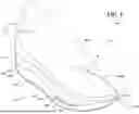


Sources:
- United States Patent and Trademark Office - verify current appl. status at the USPTO↗
Similar patent applications:
- » 20170150777
Articles of footwear and sole structures for articles of footwear - » 20170150778
Articles of Footwear and Sole Structures for Articles of Footwear - » 20210177092
Articles of footwear and sole structures for articles of footwear - » 20190142108
Articles of footwear and sole structures for articles of footwear - » 20090272008
Sole structures and articles of footwear including such sole structures - » 20250074036
POLYPROPYLENE-BASED OUTSOLE MATERIAL, FOOTWEAR SOLE STRUCTURE INCLUDING THE SAME, AND FOOTWAER ARTICLE INCLUDING THE FOOTWEAR SOLE STRUCTURE - » 20200229537
Sole structure for an article of footwear with undulating sole plate - » 20220117354
Sole structure for an article of footwear with undulating sole plate - » 20180338568
Sole structure for an article of footwear with undulating sole plate - » 20230309651
Sole structure for an article of footwear with undulating sole plate
Recent applications in this class:
- » 20260130462 2026-05-14
INTEGRATED FOOTWEAR COMPONENTS AND FOOTWEAR COMPRISING THE SAME - » 20250366562 2025-12-04
INTEGRATED FOOTWEAR COMPONENTS AND FOOTWEAR COMPRISING THE SAME - » 20250344806 2025-11-13
STEALTH FOOTWEAR - » 20250331602 2025-10-30
Sole for a Running Shoe - » 20250302145 2025-10-02
SHOE SHAPED WITH BOTTOM AND SIDE LANDING AREAS TO GUIDE MOTION - » 20250009069 2025-01-09
SHOE SOLE BLOCK POLYMER, SHOE SOLE RESIN COMPOSITION, AND SHOE SOLE - » 20240398060 2024-12-05
Footwear sole and related method of use - » 20240341403 2024-10-17
SOLE ELEMENT, FOOTWEAR ARTICLE COMPRISING SUCH A SOLE ELEMENT AND METHODS FOR MANUFACTURING SUCH A SOLE ELEMENT AND SUCH A FOOTWEAR ARTICLE - » 20240206587 2024-06-27
FOOTWEAR SOLE WITH ROPE WALL AND METHOD OF MANUFACTURE - » 20230232937 2023-07-27
Method of making a composite material
Recent applications for this Assignee:
- » 20260130504 2026-05-14
ADJUSTABLE SHELF FOR STORAGE - » 20260130465 2026-05-14
AUTOMATIC PUMP WITH RELEASE FEATURE FOR ARTICLE OF FOOTWEAR - » 20260130463 2026-05-14
SOLE STRUCTURE FOR ARTICLE OF FOOTWEAR - » 20260128606 2026-05-07
WIRELESS CHARGING SYSTEM WITH MULTI-COIL SCANNING AND LEARNING - » 20260124488 2026-05-07
DUMBBELL - » 20260123715 2026-05-07
SOLE STRUCTURE FOR ARTICLE OF FOOTWEAR - » 20260123709 2026-05-07
ARTICLE OF FOOTWEAR WITH LINER HAVING EXTERNAL GROUND PLANE - » 20260123700 2026-05-07
PUMP FOR ARTICLE OF FOOTWEAR OR APPAREL - » 20260114549 2026-04-30
SENSING DEVICE FOR FOOTWEAR - » 20260114546 2026-04-30
ARTICLE OF FOOTWEAR HAVING A SOLE STRUCTURE WITH MONOLITHIC COMPONENT OF STACKED LAYERS