RISK MITIGATION IN ELECTROLYZERS
US20260139397A1
2026-05-21
19/243,734
2025-06-20
Smart Summary: In this system, the amount of hydrogen (H2) in the oxygen (O2) released from electrolyzers is monitored. If the hydrogen concentration gets too high, a mix of water and another gas is added to dilute it, keeping it safe and preventing explosions. The system also checks if the electrolyzer is not in use or turned off. If it is, a small amount of the secondary gas is regularly introduced to maintain safe levels of any leftover hydrogen. This helps protect the electrolyzer's parts from damage. 🚀 TL;DR
Abstract:
According to an aspect, a concentration of H2 in O2 released from one or more anode compartments of an electrolyzer is measured. It is checked whether the measured concentration exceeds a predefined threshold. If the concentration exceeds the predefined threshold, a mixture of water and a secondary gas is injected into the anode compartments. The injected mixture dilutes any H2 gas present in the anode compartments so as to keep a level of the H2 gas within safe limits (thereby avoiding the formation of explosive mixtures). According to another aspect, a determination of whether the electrolyzer is in a standby or a shutdown mode is performed. In response to the determination, a minimal flow of the secondary gas is periodically introduced into the anode compartments, so as to keep a level of the residual H2 gas within safe limits (thereby preventing the degradation of the catalysts).
Applicant:
Interested in similar patents?
Get notified when new applications in this technology area are published.
Classification:
C25B15/023 » CPC main
Operating or servicing cells; Process control or regulation Measuring, analysing or testing during electrolytic production
C25B1/04 » CPC further
Electrolytic production of inorganic compounds or non-metals; Products; Hydrogen or oxygen by electrolysis of water
C25B9/19 » CPC further
Cells or assemblies of cells; Constructional parts of cells; Assemblies of constructional parts, e.g. electrode-diaphragm assemblies; Process-related cell features; Cells comprising dimensionally-stable non-movable electrodes; Assemblies of constructional parts thereof with diaphragms
C25B15/08 » CPC further
Operating or servicing cells Supplying or removing reactants or electrolytes; Regeneration of electrolytes
Description
PRIORITY CLAIM
The present patent application is related to and claims the benefit of priority to the co-pending US provisional patent application entitled, “RISK MITIGATION IN PROTON EXCHANGE MEMBRANE (PEM) ELECTROLYZERS”, Ser. No. 63/721,585, Filed: 18 Nov. 2024, which is incorporated in its entirety herewith to the extent not inconsistent with the description herein.
BACKGROUND
Technical Field
The present disclosure relates to electrolyzers and more particularly to risk mitigation in such electrolyzers.
Related Art
Electrolyzers are used for the production of hydrogen (H2) through water electrolysis as is well known in the relevant arts. An electrolyzer typically contains multiple electrolyzer cells (provided as one or more electrolyzer stacks), with each cell producing hydrogen at the cathode and oxygen at anode by passing an electric current and water, as is also well known in the relevant arts.
There are several risks associated with such electrolyzers. One common risk is that the simultaneous presence of generated gases such as H2 and oxygen (O2) at the anode is likely to form explosive mixtures, especially at high concentrations. Existing safety protocols emphasize strict control over operational parameters but leave room for improvement through proactive management.
Another risk is the degradation of the catalysts used in the electrolysis process. For example, oxygen evolution reaction (OER) catalysts such as iridium oxide (IrO2) are commonly used at the anode. The crossover of hydrogen to the anode, especially during standby and shutdown, can lead to the reduction of iridium oxide (IrO2) to iridium (Ir), accelerating degradation of the OER catalyst. Such degradation may reduce the operational life of the electrolyzer.
Aspects of the present disclosure are directed to mitigating such and other risks in electrolyzers.
BRIEF DESCRIPTION OF THE VIEWS OF DRAWINGS
Example embodiments of the present disclosure will be described with reference to the accompanying drawings briefly described below.
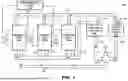
FIG. 1 illustrates an example environment (hydrogen production system) in which several aspects of the present disclosure can be implemented.
FIG. 2 is a block diagram illustrating the details of an electrolyzer stack in an embodiment.
FIG. 3 is a block diagram illustrating the details of a Proton Exchange Membrane (PEM) electrolyzer cell in an embodiment.
FIG. 4 is a flow chart illustrating the manner in which risks in electrolyzers is mitigated according to several aspects of the present disclosure.
FIG. 5 is a block diagram of a gas injection system provided according to several features of the present disclosure.
FIG. 6 is a block diagram illustrating the details of a digital processing system in which various aspects of the present disclosure are operative by execution of appropriate executable modules.
In the drawings, like reference numbers generally indicate identical, functionally similar, and/or structurally similar elements. The drawing in which an element first appears is indicated by the leftmost digit(s) in the corresponding reference number.
DETAILED DESCRIPTION
1. Overview
According to an aspect of the present disclosure, a concentration of H2 in O2 released from one or more anode compartments of an electrolyzer is measured. It is checked whether the measured concentration exceeds a predefined threshold. If the concentration exceeds the predefined threshold, a mixture of water and a secondary gas is injected into the anode compartments. The injected mixture dilutes any H2 gas present in the anode compartments so as to keep a level of the H2 gas within safe limits.
In one embodiment, the electrolyzer includes an anode, a cathode and a membrane. A voltage is applied across the anode and the cathode with water surrounding the anode and the cathode to cause production of the H2 and the O2 at the cathode and the anode respectively, an anode compartment to collect the O2 produced at the anode, in addition to any H2 that crosses over to the anode compartment.
According to one more aspect of the present disclosure, the measuring (noted above) is performed using one or more Lower Flammability Limit (LFL) detectors configured to detect flammability risk within the anode compartments. The predefined threshold is set to 50% of the Lower Flammability Limit (LFL) of H2 in O2.
According to yet another aspect of the present disclosure, the secondary gas (injected) is an inert gas selected from the group consisting of nitrogen and argon.
According to an aspect of the present disclosure, the secondary gas (injected) is atmospheric air generated using an air pump, with the atmospheric air being combined with water using an air injection mechanism to form the mixture before injecting into the anode compartments.
According to another aspect of the present disclosure, a set of operational values of the electrolyzer is received. A set of injection parameters is calculated based on the concentration of H2 in O2 and the set of operational values. The injecting (of the mixture) is controlled based on the set of injection parameters. In one embodiment, the set of operational values includes an active area of the electrolyzer, an operating temperature of the electrolyzer, a current density, an anode inlet liquid water flow rate and an anode total pressure, while the set of injection parameters includes a gas flow rate, an injection duration and an injection frequency.
According to one more aspect of the present disclosure, an amount of O2 gas in the anode compartments is monitored. A determination is made that the electrolyzer is in a shutdown mode when the amount drops below a set threshold. In response to the determination (of the shutdown mode), a minimal flow of the secondary gas is periodically introduced into the anode compartments. The minimal flow acts as a carrier gas for any residual H2 gas so as to keep a level of the residual H2 gas within safe limits.
According to yet another aspect of the present disclosure, immediately following the determining, the introducing is performed at a high frequency to quickly reduce the level of the residual H2 gas, and thereafter gradually decreasing the high frequency as the concentration of the residual H2 gas stabilizes over time.
Several aspects of the present disclosure are described below with reference to examples for illustration. However, one skilled in the relevant art will recognize that the disclosure can be practiced without one or more of the specific details or with other methods, components, materials and so forth. In other instances, well known structures, materials, or operations are not shown in detail to avoid obscuring the features of the disclosure. Furthermore, the features/aspects described can be practiced in various combinations, though only some of the combinations are described herein for conciseness.
2. Example Environment
FIG. 1 illustrates an example environment (hydrogen production system) in which several aspects of the present disclosure can be implemented. Specifically, FIG. 1 shows hydrogen production system 100 containing power sources 110-1 through 110-3, water pump 120, electrolyzer stacks 130-1 through 130-3, stack management system (SMS) 150, anode phase separator 180, and cathode phase separator 190. Electrolyzer stacks 130-1 through 130-3 are individually or collectively referred to by numeral 130, as will be clear from the context. Similar convention is used for referring to other similar components as well.
Merely for illustration, only a representative number of blocks are shown in hydrogen production system 100. Many systems contain many more electrolyzer stacks (with many electrolyzer cells described below) and other components, depending on the purpose for which the system is designed. Each block of FIG. 1 is described below in further detail.
Each of the electrolyzer stacks 130-1 through 130-3 (generally 130) is driven by a corresponding power source 110-1 through 110-3 (110) to produce a corresponding portion of hydrogen by electrolysis, as described below in further detail. Specifically, electrolyzer stack 130-2 is shown with water inlet 132 from which water is received, oxygen outlet 133 from which oxygen gas is sent along with water, and hydrogen outlet 131 from which hydrogen gas is sent also along with water. It should be noted that in the following disclosure, the term water refers to either water in liquid form or gas form (water vapor).
Though each stack is described as being powered by a corresponding power source, alternative embodiments may employ a shared power source for all or some of the stacks. In addition, practically, the content sent via oxygen outlet 133 may contain residual hydrogen, etc. The description is continued without some of such details, as not being pertinent to understanding features of the present disclosure.
Pipe 160 is used to transport water from water pump 120 to each of electrolyzer stacks 130-1 through 130-3. Pipe 140 is used to collect the mixture of hydrogen and water from the respective hydrogen outlets (131 being representative) of each electrolyzer stack 130, and transport the same to cathode phase separator 190. Pipe 170 is used to collect the mixture of oxygen and water from the respective oxygen outlets (133 being representative) of each electrolyzer stack 130, and transport the same to anode phase separator 180. It should be noted that each pipe shown in hydrogen production system 100 typically has a multi-phase flow that involves the simultaneous movement of one or two distinct phases (here gas and liquid), with these phases interacting at the end points.
Anode phase separator 180 separates oxygen from the water/oxygen mixture received from pipe 170, and releases the oxygen through output 185. The water separated in the process is released through pipe 182. Cathode phase separator 190 separates hydrogen from the water/hydrogen mixture received from pipe 140, and releases the hydrogen through output 195. The water separated in the process is released through pipe 192. The released hydrogen is dried further before being collected in suitable containers.
Water pump 120 receives water from external source 125 (when starting the electrolysis and for any short fall of water during electrolysis) and also from pipes 182 and 192, and supplies the requisite water to each of the electrolyzer stacks 130 via pipe 160. The water may be processed for purification, etc., in a known way, before being supplied to electrolyzer stacks 130 via pipe 160.
Stack management system (SMS) 150 controls various components of FIG. 1 as required for production of hydrogen. Only the connection to power sources 110 is shown for illustration, though SMS 150 may be connected to other components at least to coordinate the activities of hydrogen production system 100. In one embodiment, SMS 150 controls the operation of power sources 110 to regulate the voltage and current sent to each of electrolyzer stacks 130. Such power based control may ensure that the electrolyzer stacks operates at its peak efficiency, maximizing hydrogen production per unit of electricity consumed. SMS 150, anode phase separator 180 and cathode phase separator 190 may be implemented in a known way.
The description is continued with respect to the details of an electrolyzer stack in one embodiment.
3. Electrolyzer Stack
FIG. 2 is a block diagram illustrating the details of an electrolyzer stack (assumed to be 130-2) in an embodiment. Electrolyzer stack 130-2 is shown containing three cells 250-1 through 250-3, between end plates 210-1 and 210-2. The three cells are shown realized by monopolar plates 215-1 and 215-2, and bipolar plates 220-1 and 220-2 and membrane electrode assemblies (MEA) 230-1 through 230-3.
Specifically, cell 250-1 is constituted of monopolar plate 215-1 (acting as cathode), MEA 230-1 and upper side of bipolar plate 220-1 (acting as anode). Cell 250-2 is constituted of lower side of bipolar plate 220-1 (acting as cathode), MEA 230-2 and upper side of bipolar plate 220-2 (acting as anode). Cell 250-3 is constituted of lower side of bipolar plate 220-2 (acting as cathode), MEA 230-3 and monopolar plate 215-2 (acting as anode). However, it may be readily appreciated that the cells can be realized based on monopolar plates (instead of using bipolar plates) alone in alternative embodiments.
Power source 110-2 provides the required potential difference to drive the electrolysis reaction between the anode(s) and the cathode(s) in the stack. Power source 110-2 may provide a current (formed by electrons e-) via external circuit 245. End plates 210-1 and 210-2 provide structural support and electrical connections at the ends of the stack.
Bipolar plates 220-1 and 220-2 separate individual cells in the stack while providing anode and cathode functionality to adjacent cells, as noted above. The plates are also used for distributing water to the anode(s), ensuring electrical connectivity between cells, and facilitating gases (oxygen and hydrogen) and heat transfer. Monopolar plate 215-1 allows hydrogen gas to leave the cathode and monopolar plate 215-2 allows oxygen gas to leave the anode. Bipolar plates 220 and monopolar plates 215 are often made of titanium or other suitable materials for electrolysis, as is well known in the arts.
MEA 230 enables the electrochemical process that splits water into hydrogen and oxygen, and typically consists of a membrane, catalyst layers, and gas diffusion layers. The thin membrane allows the passage of some charged particles/ions (such as positively charged hydrogen ions/protons) while acting as an insulator for other particles/ions (such as electrons). Catalyst layers are thin layers containing electrocatalysts that facilitate the electrochemical reactions at the anode and cathode. Gas diffusion layers are porous layers that facilitate the transport of gases (oxygen and hydrogen) to and from the catalyst layers.
It may be appreciated that the above noted components may be used to implement different types of electrolysis processes such as Alkaline water electrolysis, Proton Exchange Membrane Electrolysis (PEM), Solid Oxide Electrolysis (SOEC) and Anion Exchange Membrane (AEM) Electrolysis.
In an embodiment described herein, the membrane in MEA 230 is a proton exchange membrane (PEM) which is typically made of a solid polymer electrolyte. PEM allows hydrogen ions (protons), but not electrons, to pass through from anode(s) to cathode(s). PEM electrolysis employs noble metal catalysts, typically using Iridium (IrO2) at the anode and platinum (Pt black) at the cathode.
Thus, each of cells 250 represents a single PEM cell that performs the splitting of water into hydrogen and oxygen. The operational view of a single PEM cell is described next.
4. PEM Electrolyzer Cell
FIG. 3 is a block diagram illustrating the details of a Proton Exchange Membrane (PEM) electrolyzer cell in an embodiment. PEM electrolyzer cell 250-1 is shown containing anode 310 (incorporating anode catalyst 312), anode compartment 315, cathode 320, cathode compartment 325, PEM 350, electrical connections 341 and 342 (driven by power source 110-2), anode inlet 132-A, anode outlet 133-A and cathode outlet 131-A. Each block of FIG. 3 is described below in further detail.
At anode compartment 310, water (H2O) is received via inlet 132-A (a part of 132). Within the anode compartment 310, anode 310 facilitates oxidation of the water molecules, thereby splitting the water molecules into protons (H ions), electrons (e), and oxygen gas (O2). Also, it is noted that the oxygen gas generated at anode 310 is a byproduct of PEM electrolyzer cell 250-1.
Catalyst 312 increases the oxidation of water molecules at anode 310 and/or lowers the energy requirements for such oxidation, as is well known in the arts. Catalyst 312 is typically composed of metal-oxide based catalysts such as iridium oxide (IrO2), ruthenium oxide (RuO2), or iridium ruthenium oxide (IrRuOx). Electrons generated at anode 310 are directed through an external circuit (provided via electrical connections 341 and 342) to cathode 320.
PEM 350 allows only protons to pass through, preventing gas mixing between the anode compartment 315 and cathode compartment 325. Cathode 320 combines protons with electrons to form hydrogen gas (H2), which exits the cathode compartment 325 through outlet 131-A (a part of 131). Simultaneously, a gas mixture composed of oxygen gas generated at anode 310, hydrogen gas due to crossover through the PEM 350, and water is sent out via outlet 133-A (part of 133). Electrical connections 341 and 342 (driven by power source 110-2) provide the required potential difference to drive the electrolysis reaction between anode 310 and cathode 320. Thus, PEM electrolyzer cell 250-1 is designed to operate as part of an electrochemical system designed to produce hydrogen gas (H2) through water electrolysis.
As noted in the background, electrolyzers have several associated risks such as explosive mixtures formed by H2 and O2 present in anodes and the degradation of catalysts used in the electrolysis process (due to the presence of residual H2 gas). In the following disclosure, the term “electrolyzer” represents any of a hydrogen production system (such as 100 of FIG. 1), an electrolyzer stack (such as 130-2 of FIG. 2) or an electrolyzer cell (such as PEM cell 250-1 of FIG. 3).
Aspects of the present disclosure mitigate the risks in electrolyzers as described below with examples.
5. Mitigating Risk in Electrolyzers
FIG. 4 is a flow chart illustrating the manner in which risks in electrolyzers is mitigated according to several aspects of the present disclosure. The flowchart is described with respect to the systems of FIGS. 1, 2 and 3, merely for illustration. However, many of the features can be implemented in other environments also without departing from the scope and spirit of several aspects of the present invention, as will be apparent to one skilled in the relevant arts by reading the disclosure provided herein.
In addition, some of the steps may be performed in a different sequence than that depicted below, as suited to the specific environment, as will be apparent to one skilled in the relevant arts. Many of such implementations are contemplated to be covered by several aspects of the present invention. The flow chart begins in step 401, in which control immediately passes to step 410.
In step 410, a concentration of H2 in O2 released from anode compartments (such as 315) of an electrolyzer is measured. The measurement is typically performed on the output (185) of anode phase separator 180. According to an aspect, the measurement is performed using one or more Lower Flammability Limit (LFL) detectors configured to detect flammability risk within the one or more anode compartments.
In step 420, a check of whether the measured concentration is above a predefined threshold is performed. According to an aspect, the predefined threshold is set to 50% of the Lower Flammability Limit (LFL) of H2 in O2. Control passes to step 440 if the measured concentration is above the predefined threshold, and to step 460 otherwise.
In step 440, a mixture of water and a secondary gas is injected into the anode compartments (via pipe 160/water inlet 132/anode inlet 132-A). The injected mixture dilutes any H2 gas present in the one or more anode compartments so as to keep a level of the H2 gas within safe limits. According to an aspect, the secondary gas is an inert gas selected from the group consisting of nitrogen and argon.
According to another aspect described in below sections, the secondary gas is atmospheric air generated using an air pump. The atmospheric air is combined with water using an air injection mechanism to form the mixture before being injected into the one or more anode compartments. Control passes to step 460.
In step 460, a determination of whether the electrolyzer is in a standby mode or a shutdown mode is performed. In one embodiment, the determination is performed by monitoring the operation of the power source (110). If the power source is on but no current is delivered to the electrolyzer, the electrolyzer is deemed to be in standby mode. If the power source is off, the electrolyzer is deemed to be in shutdown mode. It may be noted that in both these modes, the electrolyzer is not producing hydrogen (and accordingly may cause the degradation of the catalysts).
Alternatively, an amount of O2 gas present in the anode compartments may be monitored (using one or more O2 sensors). If the monitored amount of O2 is less than a set threshold (for example, 0), the electrolyzer is deemed to be in the standby/shutdown mode. Control passes to step 480 if the electrolyzer is determined to be in the standby/shutdown mode, and to step 410 otherwise (where the measuring of H2 in O2 is continued to be performed). In step 480, a minimal flow of the secondary gas (such as air) is introduced periodically into the anode compartments. The minimal flow acts as a carrier gas for any residual H2 gas so as to keep a level of the residual H2 gas within safe limits.
According to an aspect, immediately following the determination, the introduction of the minimal flow is performed at a high frequency to quickly reduce the level of the residual H2 gas. Thereafter, the high frequency is gradually decreased as the concentration of the residual H2 gas stabilizes over time. Control passes to step 410, to continue the measuring and monitoring the presence of H2 gas in the anode compartments of the electrolyzer.
Thus, aspects of the present disclosure provide for a gas injection system that mitigates the risks in electrolyzers. The system intermittently injects a mixture of water and a secondary gas (air) into the anode compartments, which dilutes H2 concentration in O2 in the electrolyzer, lowering the risk of explosive gas mixtures. Additionally, the air introduction strategy mitigates catalyst degradation by preventing reduction of the catalyst during shutdown conditions, thereby improving the lifetime of the stack.
The description is continued assuming that a hydrogen production system (such as 100) is modified to integrate an air injection mechanism into the anode water circulation loop (160-130-180-120 of FIG. 1). A controllable air pump with adjustable flow rates is included, allowing dynamic air injection based on operational conditions and H2 concentration in O2 gas measurements. A real-time monitoring system continuously tracks gas compositions, particularly H2 concentration in O2, and adjusts the air flow accordingly to ensure safety and system optimization. The manner in which such a gas injection system is implemented is described in detail below.
6. Air Injection System
FIG. 5 is a block diagram of an air injection system (500) provided according to several features of the present disclosure. The system is shown containing anode phase separator 180, sensors 510A-510C, monitoring system 520, paths 522 and 532, control system 530, air pump 540, tube/pipe 545, air injection mechanism 550. Each of the blocks of the Figure is described in detail below.
As described above, anode phase separator 180 is designed to separate water from the gas mixture received from outlet 170, which is connected to one or more anode compartments (such as 315 in PEM electrolyzer cell 300 as shown in FIG. 3). Anode phase separator 180 typically includes a filtering system (having a series of filters or membranes) that selectively allows the gases to pass through, while directing separated water to pipe 182. It should be noted that the gas mixture in pipe 185 is primarily composed of oxygen gas and water vapor, with trace amounts of hydrogen gas.
Monitoring system 520 uses operational values to measure the hydrogen concentration in the gas mixture from the anode phase separator 180. Monitoring system 520 may use sensors 510A-510C such as Lower Flammability Limit (LFL) detectors deployed in pipe 185, to monitor hydrogen levels in the gas mixture. Monitoring system 520 may use other sensors (not shown) such as temperature sensors to measure stack inlet and outlet temperatures, current sensors, water flow sensors, and anode inlet and outlet pressure sensors. Some of the sensors may be provided associated with system 100, with corresponding operational values being received via path 522. Other operational values may be pre-configured and/or received as user input (with path 522 being connected to a client system).
Monitoring system 520 transmits these signals to control system 530, which uses them to calculate the total volumetric gas flow rate based on hydrogen concentration, along with the effective oxygen and water vapor flow rates. In an embodiment, monitoring system 520 is limited to gathering and sending raw sensor data to control system 530. In another embodiment, monitoring system 520 may also process sensor data to calculate molar, volumetric, and air flow rates before sending this information to control system 530.
Control system 530 receives either raw or processed data from monitoring system 520 and determines the necessary air flow rate, injection frequency, duration, and intermittency into the anode loop, providing appropriate signals to the air pump 540. For example, if monitoring system 520 only provides sensor readings, control system 530 performs calculations for molar, volumetric, and air flow rates. In cases where monitoring system 520 provides pre-calculated rates, control system 530 focuses solely on adjusting injection parameters (frequency, duration, and intermittency) into the anode loop.
It may be appreciated that control system 530 performs the calculations for the air flow rates when the determined/measured hydrogen concentration (DH) is greater than a target hydrogen content (TH). During normal operation of an electrolyzer, the primary safety threshold for hydrogen in oxygen is set at 50% of the Lower Flammability Limit (LFL), equivalent to 2% H2 in O2, based on an LFL of 4% H2 in O2. Such a threshold is an accepted industry standard and triggers an automatic shutdown of the electrolyzer if exceeded. For enhanced safety, a proactive limit of 1% H2 in O2 (or air) is also established, regardless of variations in operating pressure, temperature, or hydrogen production rate. In the following disclosure, the target H2 concentration desirable at anode compartments is assumed to be pre-configured to 1.0% (though in alternative embodiments, TH may be set to any desired predetermined safety limit).
As such, control system 530 first compares DH with TH. If the determined hydrogen concentration is greater than the target (DH>TH), control system 530 calculates the above noted air flow rates. The required air flow rate is calculated to dilute the H2 gas at the anode compartments from the determined concentration (DH) to the target concentration (TH). Control system 530 then sends appropriate signals to air pump 540 to generate the required air flow rate to be achieved. If the determined concentration is less than or equal to the target (DH<=TH), no further action is performed by control system 530.
Control system 530 is also designed to determine of whether the electrolyzer is in a standby mode or a shutdown mode. As noted above, in one embodiment, control system 530 receives (via path 532) signals from power sources 110, and determines that the electrolyzer is in standby mode when the received signals indicate that the power source is on but no current is delivered to the electrolyzer, and in shutdown mode when the received signals indicate that the power source is off. In addition, control system 530 may compare the effective O2 flow rate received from monitoring system 520 with a threshold (0 or an appropriate small value) to detect a standby/shutdown condition of the electrolyzer. Upon detection of such a standby/shutdown condition, control system 530 may activate appropriate hardware/software to cause intermittent/periodic introduction of air into the anode loop.
Air pump 540 is a motorized unit that draws air from the surrounding atmosphere via an inlet and supplies it to air injection mechanism 550 through pipe/tube 545. Air pump 540 provides air at a controlled, adjustable flow rate to maintain appropriate dilution levels of hydrogen in the anode compartments. Air pump 540 system may also include a gas filter to remove impurities from the air, ensuring the water resistivity required for the operation of the electrolyzer is maintained.
Air injection mechanism 550 is a chamber where air from pump 540 is combined with water delivered through pipe 555 before being directed to anode inlet pipe 160. The chamber within air injection mechanism 550 may contain pistons, valves, diffusers, and sub-chambers to facilitate the controlled mixing of air and water.
Thus, air injection system 500 is implemented according to several aspects of the present disclosure to mitigate the risks in electrolyzers. The monitoring system (520) is primarily responsible for data acquisition (and, in some cases, data processing), while the control system (530) uses that data to make decisions and execute actions.
Specifically, the combination of monitoring system (520) and control system (530) operate to receive a set of operational values (such an active area of the electrolyzer, an operating temperature of the electrolyzer, a current density, an anode inlet liquid water flow rate and an anode total pressure) of the electrolyzer, calculate a set of injection parameters (a gas flow rate, an injection duration and an injection frequency) based on said concentration of H2 in O2 (determined from sensors 510A-510C) and the set of operational values and control the injecting of the mixture of air and water based on the calculated set of injection parameters (by controlling the operation of air pump 540).
It may be appreciated that though described above with respect to the usage of air, any alternative gas (in place of air) may be used to maintain appropriate dilution levels of hydrogen in the anode compartments by appropriate modification of air pump 540 and air injection mechanism 550. Example of such alternative gases may be nitrogen (N2) and noble gases like helium, neon, argon, krypton, xenon, and radon may also be used to maintain appropriate dilution levels of hydrogen in the anode compartments. However, using such alternative gases may necessitate the storage of compressed gas cylinders, which may increase both the system footprint and costs.
The operation of the various components of air injection system 500 during normal operation and system shutdown (that is when the electrolyzer cell/stack is inactive/not operative) is described in detail below.
6. Sample Operation
During normal operation, monitoring system 520 continuously gathers and processes data from the hydrogen production system (100) to ensure safe and efficient hydrogen production. Specifically, monitoring system 520 collects operational values such as stack active area (assumed to be 1000 cm2), Faradaic efficiency (95%), operating temperature (70° C. or 343 K), current density (2 A/cm2), anode inlet liquid water flow rate (6 L/min), and anode total pressure (1 atm) and calculates the air flow rates based on the received values. In addition, monitoring system 520 also determines the hydrogen concentration (1.8%) in the filtered mixture received from anode phase separator 180. An example calculation done by monitoring system 520 is described below:
Step 1: Calculate Molar Flow Rate of O2
Using Faraday's law, the molar flow rate of O2, {dot over (n)}[O2], generated is:
n . [ O 2 ] = I × Faradaic efficiency 4 F
where
-
- I is the total current (current density×stack active area);
- F is Faraday's constant (96485 C/mol); and
- 4 is the number of electrons needed to produce one O2 molecule.
Substituting the values noted above:
n . [ O 2 ] = ( 2 0 0 0 × 0 . 9 5 ) / ( 4 × 96485 ) ≈ 0.00492 mol / s
Thus, the molar flow rate of 02, {dot over (n)}[O2] is 0.00492 mol/s.
Step 2: Calculate Molar Flow Rate of Water Vapor (H2O)
Using the saturation pressure of water vapor at 70° C. (31.8 kPa) in a 1 atm system: the molar flow rate of H2O, {dot over (n)}[H2O] is:
n . [ H 2 O ] P [ H 2 O ] × V [ H 2 O ] R × T P [ H 2 O ] = 31.8 kPa V [ H 2 O ] = 0 . 0 06 / 60 R = 8. 314 J / ( mol · K ) T = 343 K
Substituting the values noted above:
n . [ H 2 O ] = 3 1 8 0 0 × ( 0 . 0 06 / 60 ) 8 . 3 1 4 × 3 4 3 = 0 . 0 01115 mol / s
Thus, the molar flow rate of H2O, 0.001115 mol/s.
Step 3: Calculate Molar Flow Rate of Hydrogen (H2) in Oxygen (O2)
Given the total molar flow rate of O2 and H2O:
n . [ total ] = n . [ O 2 ] + n . [ H 2 O ] = 0 . 0 0 4 9 2 + 0 . 0 0 1 1 1 5 = 0 . 0 06035 mol / s
With 1.8% H2 in the anode loop and the remaining 98.2% is O2 and water vapor, the molar flow rate of hydrogen is determined as:
n . [ H 2 ] = 0 . 0 0 6 0 3 5 × 1.8 98.2 = 0 . 0 0 01106 mol / s
Step 4: Calculate Total Molar Flow Rate
The total molar flow rate of O2, H2O vapor, and H2 is:
n . [ total ] = n . [ O 2 ] + n . [ H 2 O ] + n . [ H 2 ] == 0.00492 + 0 . 0 0 1 1 1 5 + 0 . 0 0 0 1 1 0 6 = 0 . 0 0 61456 mol / s
Step 5: Convert Molar Flow Rate to Volumetric Flow Rate
Using the ideal gas law:
V . [ total ] = n . [ total ] × R × T P V . [ total ] = 0 . 0 0 6 1 4 5 6 × 0 . 0 8 2 1 × 3 4 3 1 = 0 . 1 731 L / s = 10.39 L / min
Monitoring system 520 then transmits the values of the volumetric flow rate to control system 530, which in turn calculates a required air flow rate to dilute H2 from 1.8% (determined concentration) to 1.0% (target concentration, as noted above). An example calculation done by control system 530 is described below:
Step 6: Calculate Required Air Flow Rate
To reduce the H2 concentration from 1.8% to 1.0%, the system increases the total flow rate in the anode loop so that H2 makes up only 1.0% of the total gas volume.
Required total flow rate = Total gas flow rate before dilution × ( Initial H 2 concentration / Target H 2 concentration )
Substituting the values noted above:
Required total flow rate = 10.39 L / min × ( 1.8 % / 1. % ) = 18.7 L / min
The air flow rate needed is the difference between the required total flow rate and the initial adjusted anode loop flow rate:
V . [ air ] = 18.7 L / min = 10.39 L / min = 8.31 L / min
Thus, the required air flow rate to dilute the H2 concentration from 1.8% to 1.0% in the anode loop, considering 70° C. operation and H2O vapor presence, is 8.31 L/min.
During system shutdown, control system 530 identifies that the electrolyzer is inactive based on data from monitoring system 520, which indicates that oxygen levels in anode compartments have dropped below a set threshold (e.g., zero). In shutdown mode, control system 530 calculates the appropriate air introduction/injection rate based on the total volume of the anode loop, which includes the anode portion of the stack, connecting piping, and the anode phase separator.
To maintain safety, periodic hydrogen detection within the anode loop continues, even though no active O2 production is occurring. A minimal air flow is periodically introduced to keep any residual H2 levels within safe limits and to act as a carrier gas for H2 detection. Immediately following shutdown, air injection may occur more frequently to quickly reduce residual H2 levels, with the frequency gradually decreasing as the hydrogen concentration stabilizes over time.
Such intermittent air injection prevents the reduction of metal oxide-based catalysts, such as iridium oxide (IrO2), to elemental iridium (Ir) by crossover hydrogen in the anode compartment. By maintaining an oxidative environment, the system mitigates catalyst degradation, preserving the stability and extending the operational life of the OER catalyst.
It may be appreciated that monitoring system 520 samples conditions of the electrolyzer at different time points, possibly over a pre-defined period. Such sampling can be periodic or event-driven. For example, monitoring system 520 may sample continuously during normal operation to maintain dynamic and real-time hydrogen levels in the gas mixture or adjust the sampling frequency during shut-down. As noted above, the sampling is taken from Lower Flammability Limit (LFL) detectors to monitor hydrogen levels in the gas mixture, temperature sensors to measure stack inlet and outlet temperatures, current sensors, water flow sensors, and anode inlet and outlet pressure sensors.
Thus, air injection system 500 dilutes H2 concentration in O2, lowering the risk of explosive gas mixtures. Additionally, the air injection strategy mitigates catalyst degradation during shutdown conditions, thereby improving the lifetime of the stack. Some of the advantages of the present disclosure are described in detail below.
7. Advantages
One advantage is safety enhancement. By maintaining H2 concentrations below critical levels [<50% of the Lower Flammability Limit (LFL) for H2 in O2], the air dilution method (described above) significantly reduces the risk of ignition or explosion. N2 serves as an inert component, lowering the reactivity of the gas mixture in the anode compartment further.
Another advantage is improved catalyst longevity. The intermittent air injection during shutdown mitigates the reduction of IrO2 to Ir, decreasing the degradation rate of the OER catalyst. Such a system results in longer stack lifetimes, reducing maintenance costs and improving system reliability.
Such a system also facilitates the use of thinner membranes, which reduces ohmic resistance and improves the overall efficiency of electrolysis. The above system can achieve higher efficiency with thinner membranes. For example, in place of Nafion membranes like N115 (having a thickness of 127 μm), N117 (183 μm), and N1110 (254 μm) typically utilized in PEM electrolyzers, PEM electrolyzer cell 100 provided according to aspect of the present disclosure may use membranes having thickness less than 127 μm such as the M275.80 (80 μm) from W. L. Gore & Associates, and N112 (51 μm) and NE1135 (89 μm) membranes from Dupont. By addressing hydrogen crossover issues, this method significantly reduces ohmic resistance. Lower resistance enhances the efficiency of the electrolyzer, reducing energy consumption per unit of hydrogen produced and contributing to a more cost-effective and sustainable hydrogen production process.
It may be appreciated that the above noted features also provide operational flexibility. The system allows the electrolyzer to operate safely across a wider range of conditions, including dynamic load changes, without compromising safety margins. The features enable faster start-up and shutdown cycles while maintaining safety and preserving catalyst integrity.
In addition, the features provide a cost-effective solution. Utilizing ambient air eliminates the need for expensive inert gasses or specialized gas-handling systems. The integration of air pumps and control systems is straightforward, ensuring compatibility with existing PEM electrolyzer designs.
Thus, the gas injection system (200) offers a comprehensive solution for enhancing both the safety and performance of PEM electrolyzers (100). By dynamically controlling the injection of air into the anode compartment, the system mitigates the risks associated with H2 and O2 mixtures, preserves the stability of the OER catalyst, and allows the use of thinner, more efficient membranes. The combination of improved safety, increased efficiency, and extended stack life positions this invention as a significant advancement in electrolyzer technology, potentially setting a new industry standard for hydrogen production.
It should be appreciated that the features described above can be implemented in various embodiments as a desired combination of one or more of hardware, software, and firmware. The description is continued with respect to an embodiment in which various features are operative when appropriate executable modules described above are executed.
8. Digital Processing System
FIG. 6 is a block diagram illustrating the details of digital processing system 600 in which various aspects of the present disclosure are operative by execution of appropriate executable modules. Digital processing system 600 may correspond to stack management system 150, monitoring system 520 or control system 530.
Digital processing system 600 may contain one or more processors such as a central processing unit (CPU) 610, random access memory (RAM) 620, secondary memory 630, graphics controller 660, display unit 670, network interface 680, and input interface 690. All the components except display unit 670 may communicate with each other over communication path 650, which may contain several buses as is well known in the relevant arts. The components of FIG. 6 are described below in further detail.
CPU 610 may execute instructions stored in RAM 620 to provide several features of the present disclosure. CPU 610 may contain multiple processing units, with each processing unit potentially being designed for a specific task. Alternatively, CPU 610 may contain only a single general-purpose processing unit.
RAM 620 may receive instructions from secondary memory 630 using communication path 650. RAM 620 may contain software instructions constituting a shared environment and/or other user programs (such as other applications, DBMS, etc.). In addition to shared environment, RAM 620 may contain other software programs such as device drivers, virtual machines, etc., which provide a (common) run time environment for execution of other/user programs.
Graphics controller 660 generates display signals (e.g., in RGB format) to display unit 670 based on data/instructions received from CPU 610. Display unit 670 contains a display screen to display the images defined by the display signals. Input interface 690 may correspond to a keyboard and a pointing device (e.g., touch-pad, mouse) and may be used to provide inputs. Network interface 680 provides connectivity to a network (e.g., using Internet Protocol), and may be used to communicate with other systems connected to the networks.
Secondary memory 630 may contain hard drive 635, flash memory 636, and removable storage drive 637. Secondary memory 630 may store the data (e.g., measurements, determined amount of oxygen, calculated amount of air to be injected, etc.) and software instructions (for implementing the actions of FIG. 4, implementing some of the blocks of FIG. 5), which enable digital processing system 600 to provide several features in accordance with the present disclosure. The code/instructions stored in secondary memory 630 may either be copied to RAM 620 prior to execution by CPU 610 for higher execution speeds, or may be directly executed by CPU 610.
Some or all of the data and instructions may be provided on removable storage unit 640, and the data and instructions may be read and provided by removable storage drive 637 to CPU 610. Removable storage unit 640 may be implemented using medium and storage format compatible with removable storage drive 637 such that removable storage drive 637 can read the data and instructions. Thus, removable storage unit 640 includes a computer readable (storage) medium having stored therein computer software and/or data. However, the computer (or machine, in general) readable medium can be in other forms (e.g., non-removable, random access, etc.).
In this document, the term “computer program product” is used to generally refer to removable storage unit 640 or hard disk installed in hard drive 635. These computer program products are means for providing software to digital processing system 600. CPU 610 may retrieve the software instructions, and execute the instructions to provide various features of the present disclosure described above.
The term “storage media/medium” as used herein refers to any non-transitory media that store data and/or instructions that cause a machine to operate in a specific fashion. Such storage media may comprise non-volatile media and/or volatile media. Non-volatile media includes, for example, optical disks, magnetic disks, or solid-state drives, such as storage memory 630. Volatile media includes dynamic memory, such as RAM 620. Common forms of storage media include, for example, a floppy disk, a flexible disk, hard disk, solid-state drive, magnetic tape, or any other magnetic data storage medium, a CD-ROM, any other optical data storage medium, any physical medium with patterns of holes, a RAM, a PROM, and EPROM, a FLASH-EPROM, NVRAM, any other memory chip or cartridge.
Storage media is distinct from but may be used in conjunction with transmission media. Transmission media participates in transferring information between storage media. For example, transmission media includes coaxial cables, copper wire and fiber optics, including the wires that comprise bus 650. Transmission media can also take the form of acoustic or light waves, such as those generated during radio-wave and infra-red data communications.
References throughout this specification to “one embodiment”, “an embodiment”, or similar language means that a particular feature, structure, or characteristic described in connection with the embodiment is included in at least one embodiment of the present disclosure. Thus, appearances of the phrases “in one embodiment”, “in an embodiment” and similar language throughout this specification may, but do not necessarily, all refer to the same embodiment.
Furthermore, the described features, structures, or characteristics of the disclosure may be combined in any suitable manner in one or more embodiments. In the above description, numerous specific details are provided such as examples of programming, software modules, user selections, network transactions, database queries, database structures, hardware modules, hardware circuits, hardware chips, etc., to provide a thorough understanding of embodiments of the disclosure.
9. Conclusion
While various embodiments of the present disclosure have been described above, it should be understood that they have been presented by way of example only, and not limitation. Thus, the breadth and scope of the present disclosure should not be limited by any of the above-described exemplary embodiments, but should be defined only in accordance with the following claims and their equivalents.
It should be understood that the figures and/or screen shots illustrated in the attachments highlighting the functionality and advantages of the present disclosure are presented for example purposes only. The present disclosure is sufficiently flexible and configurable, such that it may be utilized in ways other than that shown in the accompanying figures.
Further, the purpose of the following Abstract is to enable the Patent Office and the public generally, and especially the scientists, engineers and practitioners in the art who are not familiar with patent or legal terms or phraseology, to determine quickly from a cursory inspection the nature and essence of the technical disclosure of the application. The Abstract is not intended to be limiting as to the scope of the present disclosure in any way.
Claims
What is claimed is:1. A method performed associated with an electrolyzer, the method comprising:
measuring a concentration of H2 in O2 released from one or more anode compartments of said electrolyzer;
checking whether said concentration exceeds a predefined threshold; and
if said concentration exceeds said predefined threshold, injecting a mixture of water and a secondary gas into said one or more anode compartments, wherein said mixture dilutes any H2 gas present in said one or more anode compartments so as to keep a level of said H2 gas within safe limits.
2. The method of claim 1, wherein electrolyzer comprises an anode, a cathode and a membrane, said method further comprising applying voltage across said anode and said cathode with water surrounding said anode and said cathode to cause production of said H2 and said O2 at said cathode and said anode respectively, an anode compartment to collect said O2 produced at said anode, in addition to any H2 that crosses over to said anode compartment.
3. The method of claim 1, wherein said measuring is performed using one or more Lower Flammability Limit (LFL) detectors configured to detect flammability risk within said one or more anode compartments,
wherein said predefined threshold is set to 50% of the Lower Flammability Limit (LFL) of H2 in O2.
4. The method of claim 3, wherein said secondary gas is selected from the group consisting of nitrogen and an inert gas such as argon.
5. The method of claim 1, wherein said secondary gas is atmospheric air generated using an air pump,
wherein said atmospheric air is combined with water using an air injection mechanism to form said mixture before said injecting into said one or more anode compartments.
6. The method of claim 5, further comprising:
receiving a set of operational values of said electrolyzer;
calculating a set of injection parameters based on said concentration of H2 in O2 and said set of operational values; and
controlling said injecting based on said set of injection parameters.
7. The method of claim 6, wherein said set of operational values comprises an active area of said electrolyzer, an operating temperature of said electrolyzer, a current density, an anode inlet liquid water flow rate and an anode total pressure,
wherein said set of injection parameters comprises a gas flow rate, an injection duration and an injection frequency.
8. The method of claim 1, further comprising:
determining that said electrolyzer is in a standby mode or a shutdown mode; and
in response to said determining, introducing periodically, a minimal flow of said secondary gas into said one or more anode compartments, wherein said minimal flow acts as a carrier gas for any residual H2 gas so as to keep a level of said residual H2 gas within safe limits.
9. The method of claim 8, wherein immediately following said determining, said introducing is performed at a high frequency to quickly reduce said level of said residual H2 gas, and thereafter gradually decreasing said high frequency as the concentration of said residual H2 gas stabilizes over time.
10. A gas injection system associated with an electrolyzer, said system comprising:
a monitoring system to measure a concentration of H2 in O2 released from one or more anode compartments of said electrolyzer;
a control system to:
check whether said concentration exceeds a predefined threshold; and
if said concentration exceeds said predefined threshold, cause injection of a mixture of water and a secondary gas into said one or more anode compartments, wherein said mixture dilutes any H2 gas present in said one or more anode compartments so as to keep a level of said H2 gas within safe limits.
11. The system of claim 10, wherein electrolyzer comprises an anode, a cathode and a membrane, wherein applying a voltage across said anode and said cathode with water surrounding said anode and said cathode causes production of said H2 and said O2 at said cathode and said anode respectively, an anode compartment to collect said O2 produced at said anode, in addition to any H2 that crosses over to said anode compartment.
12. The system of claim 10, wherein said monitoring system comprises one or more Lower Flammability Limit (LFL) detectors configured to detect flammability risk within said one or more anode compartments,
wherein said predefined threshold is set to 50% of the Lower Flammability Limit (LFL) of H2 in O2.
13. The system of claim 12, wherein said secondary gas is selected from the group consisting of nitrogen and an inert gas such as argon.
14. The system of claim 10, wherein said secondary gas is atmospheric air, said system further comprising:
an air pump to generate a flow of said atmospheric air based on signals received from said control system; and
an air injection mechanism that combines said flow with water to form said mixture before said injection into said one or more anode compartments.
15. The system of claim 14, wherein said control system is operable to:
receive a set of operational values of said electrolyzer;
calculate a set of injection parameters based on said concentration of H2 in O2 and said set of operational values; and
control said injection by sending said signals based on said set of injection parameters.
16. The system of claim 16, wherein said set of operational values comprises an active area of said electrolyzer, an operating temperature of said electrolyzer, a current density, an anode inlet liquid water flow rate and an anode total pressure,
wherein said set of injection parameters comprises a gas flow rate, an injection duration and an injection frequency.
17. The system of claim 10, wherein said control system is operable to:
determine that said electrolyzer is in a standby mode or a shutdown mode; and
in response to said determination, introduce periodically, a minimal flow of said secondary gas into said one or more anode compartments, wherein said minimal flow acts as a carrier gas for any residual H2 gas so as to keep a level of said residual H2 gas within safe limits.
18. The system of claim 17, wherein immediately following said determining, said control system performs said introducing at a high frequency to quickly reduce said level of said residual H2 gas, and thereafter gradually decreases said high frequency as the concentration of said residual H2 gas stabilizes over time.
19. A non-transitory machine-readable medium storing one or more sequences of instructions, wherein execution of said one or more instructions by one or more processors contained in a digital processing system cause said digital processing system to perform the actions of:
receiving a set of operational values of an electrolyzer and a concentration of H2 in O2 released from one or more anode compartments of an electrolyzer;
checking whether said concentration exceeds a predefined threshold; and
if said concentration exceeds said predefined threshold:
calculating a set of injection parameters based on said concentration of H2 in O2 and said set of operational values;
controlling, based on said set of injection parameters, an injection of a mixture of water and a secondary gas into said one or more anode compartments, wherein said mixture dilutes any H2 gas present in said one or more anode compartments so as to keep a level of said H2 gas within safe limits.
20. The non-transitory machine-readable medium of claim 19, wherein said set of operational values comprises an active area of said electrolyzer, an operating temperature of said electrolyzer, a current density, an anode inlet liquid water flow rate and an anode total pressure,
wherein said set of injection parameters comprises a gas flow rate, an injection duration and an injection frequency.
Images & Drawings included:


Sources:
- United States Patent and Trademark Office - verify current appl. status at the USPTO↗
Recent applications in this class:
- » 20260132531 2026-05-14
METHOD AND SYSTEM FOR DETECTING DAMAGE IN ELECTROCHEMICAL CELLS USING INERT GAS INJECTION AND DYNAMIC DIFFERENTIAL PRESSURE ANALYSIS - » 20260117406 2026-04-30
HYDROGEN PRODUCTION APPARATUS DETERIORATION DETECTION SYSTEM - » 20260098353 2026-04-09
SYSTEMS AND METHODS TO MONITOR MEMBRANES OF AN ELECTROLYSIS SYSTEM - » 20260062825 2026-03-05
DIAGNOSIS METHOD OF ELECTROLYTIC UNIT, DIAGNOSIS METHOD OF ELECTROLYTIC APPARATUS, DIAGNOSIS APPARATUS OF ELECTROLYTIC UNIT, OPERATION SYSTEM, AND NON-TRANSITORY STORAGE MEDIUM - » 20260043161 2026-02-12
OPERATION SUPPORT APPARATUS, OPERATION SUPPORT SYSTEM, OPERATION SUPPORT METHOD, AND NON-TRANSITORY COMPUTER READABLE MEDIUM - » 20260043160 2026-02-12
CONTROL DEVICE FOR HYDROGEN PRODUCTION FACILITY, HYDROGEN PRODUCTION FACILITY, METHOD FOR CONTROLLING HYDROGEN PRODUCTION FACILITY, AND CONTROL PROGRAM FOR HYDROGEN PRODUCTION FACILITY - » 20260022483 2026-01-22
BACKFLOW SUPPRESSION SYSTEM - » 20260022482 2026-01-22
A SYSTEM AND A METHOD FOR ESTIMATING CURRENT EFFICIENCY OF AN ELECTROLYSER - » 20250369138 2025-12-04
OPERATING AN ELECTROLYSIS CELL - » 20250369137 2025-12-04
OXYGEN GENERATION SYSTEMS FOR LOW GRAVITY APPLICATIONS