ADJUSTABLE VENETIAN BLIND BRACKET
US20260144397A1
2026-05-28
19/369,375
2025-10-27
Smart Summary: An adjustable bracket for Venetian blinds has a base plate with parts that help it fit securely. It includes a connecting plate with both vertical and horizontal sections that help with installation. A locking plate is designed to hold everything in place when the bracket is put together. Two adjusting members allow the user to change the position of the bracket easily. This design makes it simpler to secure Venetian blinds and window rods, ensuring they stay stable and can be adjusted after installation. 🚀 TL;DR
Abstract:
A venetian blind bracket includes a base plate with an extending portion and an assembly portion containing an assembly hole. A connecting plate includes vertical and horizontal portions. The vertical portion features an installation hole and the horizontal portion a through-hole. A locking plate with a pressing portion and a positioning portion that engages between the vertical portion when assembled in the installation hole. A first adjusting member extends through the assembly hole. A second adjusting member extends through the through-hole. A pushing member that is assembled at the second adjusting member abuts against the pressing portion. The pushing member, driven by the second adjusting member, drives the locking plate toward or away from the base plate, enabling convenient adjustment of the bracket position for securing venetian blinds and window rods with improved stability and ease of adjustment after installation.
Applicant:
Interested in similar patents?
Get notified when new applications in this technology area are published.
Classification:
A47H1/142 » CPC main
Curtain suspension devices; Means for mounting curtain rods or rails; Brackets for supporting rods or rails for supporting rods
A47H1/122 » CPC further
Curtain suspension devices; Means for mounting curtain rods or rails; Adjustable mountings for curtain rods
Description
BACKGROUND OF THE INVENTION
1. Fields of the Invention
-
- This is a Continuation-In-Part patent application of Applicant's former patent application with application No. Ser. No. 18/959,695, filed on Nov. 26, 2024.
2. Descriptions of Related Art
Generally speaking, a venetian blind bracket is used to secure window curtains to an existing window rod or wall surface. Through the support provided by the bracket, curtains can be securely suspended and adjusted in opening or angle as needed, achieving effects of light blocking, heat insulation, and aesthetic appeal. Therefore, the stability of the bracket and the convenience of adjustment directly impact the installation quality and user experience of the curtains.
However, existing venetian blind brackets still have structural deficiencies. For example, the fixing method is relatively limited, typically relying on knobs or spindles for lateral adjustment. With this adjustment method, once the curtain rod and curtain assembly are installed, if users need to make further adjustments, they are often hindered and may even need to disassemble the entire curtain rod and reinstall it after adjustment. Additionally, the existing bracket exhibits poor stability after assembly, as the bracket often cannot fit tightly against the original window rod, creating risks of loosening, tilting, or detachment, which affects the stability and service life after installation. In other words, traditional venetian blind brackets can only be adjusted in a single direction, so venetian blinds frequently experience problems such as unstable support, excessive gaps, or positional deviation after installation, which not only affects the shading effectiveness and overall aesthetics but also reduces user convenience.
The present invention intends to provide a venetian blind bracket that can quickly and conveniently be assembled with an existing window rod, and during subsequent adjustments, the assembly of the curtain rod does not hinder the adjustment operation. The venetian blind bracket design overcomes the aforementioned deficiencies and meets public demand.
SUMMARY OF THE INVENTION
The present invention relates to a venetian blind bracket and comprises a base plate having an extending portion and an assembly portion. One end of the extending portion is connected to one end of the assembly portion, and the other end of the assembly portion has an assembly hole. A connecting plate is connected to the base plate. The connecting plate has a vertical portion and a horizontal portion. One end of the vertical portion is connected to the extending portion, and the other end of the vertical portion is connected to the horizontal portion. The vertical portion has an installation hole disposed along a longitudinal direction thereof. The horizontal portion has a through-hole.
A locking plate is movably assembled in the installation hole. The locking plate has a pressing portion and a positioning portion. One end of the pressing portion is connected to the positioning portion. When the locking plate is locked in the installation hole, the vertical portion is located between the pressing portion and the positioning portion. A first adjusting member movably extends through the assembly hole. A second adjusting member has one end thereof movably assembled in the through-hole.
A pushing member is movably assembled at the end of the second adjusting member that extends through the through-hole. The pushing member movably abuts against the pressing portion, and driven by the second adjusting member to drive the locking plate toward or away from the base plate.
The primary object of the present invention is to enhance the adjustability and operational convenience of venetian blind brackets after installation. It overcomes the limitations of conventional structures that can only provide lateral locking, which restricts adjustment once the curtain rod and the blind assembly are installed. Traditional designs often require users to partially disassemble components to make adjustments due to spatial or structural constraints, resulting in complicated adjustment procedures that may compromise assembly stability. The present invention addresses these deficiencies by enabling multi-directional adjustment without disassembly.
The present invention will become more obvious from the following description when taken in connection with the accompanying drawings which show, for purposes of illustration only, a preferred embodiment in accordance with the present invention.
BRIEF DESCRIPTION OF THE DRAWINGS
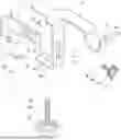
FIG. 1 is a perspective view of the present invention;
FIG. 2 is a perspective view of the present invention from another perspective;
FIG. 3 is an exploded view of the present invention;
FIG. 4 is an exploded view of the present invention from another perspective;
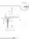
FIG. 5 is a sectional view, taken along line V-V of FIG. 1;
FIG. 6 is a schematic view showing the operation of the pushing member pushing the locking plate;
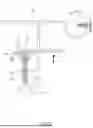
FIG. 7 is a schematic view showing the locking plate in a second configuration;
FIG. 8 is a schematic view showing the locking plate in a third configuration;
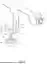
FIG. 9 is a schematic view showing the first use state of the present invention;
FIG. 10 is a schematic view showing the second use state of the present invention;
FIG. 11 is a schematic view showing the third use state of the present invention, and
FIG. 12 is a schematic view showing the fourth use state of the present invention.
DETAILED DESCRIPTION OF THE PREFERRED EMBODIMENT
Referring to FIGS. 1 through 12, the present invention provides a venetian blind bracket and comprises a base plate 1 having an extending portion 11 and an assembly portion 12, wherein one end of the extending portion 11 is connected to one end of the assembly portion 12, and the other end of the assembly portion 12 has an assembly hole 121. A connecting plate 2 is connected to the base plate 1 and has a vertical portion 21 and a horizontal portion 22. One end of the vertical portion 21 is connected to the extending portion 11, and the other end of the vertical portion 21 is connected to the horizontal portion 22. The vertical portion 21 has an installation hole 211 disposed along its longitudinal direction, and the horizontal portion 22 has a through-hole 221.
A locking plate 3 is movably assembled in the installation hole 211. The locking plate 3 has a pressing portion 31 and a positioning portion 32, wherein one end of the pressing portion 31 is connected to the positioning portion 32. When the locking plate 3 is locked in the installation hole 211, the vertical portion 21 is engaged between the pressing portion 31 and the positioning portion 32. A first adjusting member 4 movably extends through the assembly hole 121. A second adjusting member 5 with one end thereof movably assembled in the through-hole 221.
A pushing member 51 is movably assembled at the end of the second adjusting member 5 that extends through the through-hole 221. The pushing member 51 movably abuts against the pressing portion 31, and driven by the second adjusting member 5 to drive the locking plate 3 toward or away from the base plate 1. The drawings used herein are solely for illustrative purposes and are not intended to limit the scope of the present invention.
During installation, users can first connect the base plate 1 with the connecting plate 2, aligning the vertical portion 21 with the extending portion 11. Connection methods include, but are not limited to, welding, and the base plate 1 and the connecting plate 2 may also be integrally connected. Furthermore, when selecting the base plate 1, users can choose the base plates 1 with different-sized assembly portions 12 based on the size and diameter of the curtain rod 7 to meet their specific needs.
After connecting the two components, users can assemble the locking plate 3 into the installation hole 211 of the vertical portion 21. The installation hole 211 is oriented along the direction from where the vertical portion 21 connects to the base plate 1 toward where the vertical portion 21 connects to the horizontal portion 22. Based on the varying thickness of different walls and window rods 6, users can dynamically adjust the length of the locking plate 3 extending through the installation hole 211, with the positioning portion 32 engaging against the inner side of the vertical portion 21 to maintain the positioning of the locking plate 3. Various types of locking plates 3 can be selected based on different usage locations or requirements.
Next, users can drive the second adjusting member 5 to move the pushing member 51 along the direction of the through-hole 221, thereby moving the locking plate 3 toward or away from the base plate 1. This allows for precise adjustment of the position of the locking plate 3 relative to the vertical portion 21, thereby correcting the height of the bracket to accommodate different thicknesses of the window rods 6 or wall surfaces. The aforementioned assembly process requires no additional tools and can be easily completed through manual operation.
Furthermore, even after the curtain rod 7 or the blind assembly is installed, users can still fine-tune the position of the locking plate 3 by driving the pushing member 51 through the second adjusting member 5, or operate the locking plate 3 directly for micro-adjustments in vertical or front-to-back directions, unobstructed by the curtain rod 7. This further ensures the stability of bracket installation and provides greater operational flexibility compared to previous bracket structures, as illustrated in FIGS. 1 through 12.
To enhance the stability of the connection between the locking plate 3 and the window rod 6 or wall surface, the end of the pressing portion 31 that is not connected to the positioning portion 32 extends toward the base plate 1.
After the locking plate 3 is partially assembled in the installation hole 211 and the positioning portion 32 engages with the vertical portion 21, the portion of the pressing portion 31 extending toward the base plate 1 can abut and engage with the window rod 6 or wall surface. The pressing portion 31 and the positioning portion 32 of the locking plate 3 create multiple contact points, which distribute stress and increase structural strength, further preventing the possibility of bracket detachment after installation. This design is illustrated in FIGS. 1-2, FIGS. 5-6, and FIGS. 9-10.
To ensure that the locking plate 3, once assembled in the installation hole 211, remains stably engaged with the vertical portion 21 and is not easily dislodged by external impact, the positioning portion 32 further comprises a plurality of positioning areas 321. When the locking plate 3 is assembled in the installation hole 211, the vertical portion 21 locks into at least one of the positioning areas 321.
When users assemble the locking plate 3, it must be inserted at a specific angle to complete the assembly. After adjusting to an appropriate position, the position of the locking plate 3 can be adjusted by rotating or similar means, allowing the vertical portion 21 to lock into a positioning area 321 on the locking plate 3, thereby completing the assembly of the locking plate 3.
When fine-tuning adjustments are needed, the locking plate 3 can similarly be rotated or manipulated to release the positioning state, allowing for adjustment. After the adjustment is complete, the vertical portion 21 can be re-locked into another positioning area 321 by rotating or similar means, as shown in FIGS. 1-4 and FIG. 11.
To further ensure that the vertical portion 21 is firmly locked into the positioning areas 321, the positioning portion 32 further comprises a longitudinal rib 322 and a plurality of transverse ribs 323. One end of the longitudinal rib 322 is connected to the pressing portion 31, and each transverse rib 323 is equidistantly and crosswise connected to the longitudinal rib 322. Each positioning area 321 is respectively located between two adjacent transverse ribs 323 and between the transverse rib 323 closest to the pressing portion 31 and the pressing portion 31 itself.
After users assemble the locking plate 3 into the installation hole 211, they can lock the vertical portion 21 into any positioning area 321. Alternatively, when the bracket assembly is complete and fine-tuning adjustments are needed, the positioning state between the locking plate 3 and the vertical portion 21 can be released, and the locking plate 3 can be readjusted. After adjustment is complete, the vertical portion 21 can be re-locked into another positioning area 321 through rotation or similar means.
The staggered arrangement of the longitudinal rib 322 and the transverse ribs 323 creates a multi-segment positioning structure that provides anti-vibration support and prevents loosening. Even under prolonged stress or environmental vibration, the structure maintains stability without displacement as shown in FIGS. 1-4 and FIG. 11.
To prevent users from experiencing difficulties in adjusting the length of the locking plate 3 extending through the installation hole 211, the diameter of the installation hole 211 along its longitudinal direction is greater than the length of each transverse rib 323. This ensures that during pre-installation preparation or when fine-tuning adjustments are needed after installation, the structural interaction between components does not prevent the locking plate 3 from being smoothly assembled in the installation hole 211, nor does it hinder subsequent adjustment operations, as shown in FIGS. 1-4 and FIG. 11.
To facilitate user adjustment of the position of the locking plate 3, the second adjusting member 5 further comprises a second operating member 52 and a second rod 53. The second rod 53 is movably assembled in the through-hole 221, and both ends of the second rod 53 are respectively movably connected to the second operating member 52 and the pushing member 51.
When users need to adjust the position of the locking plate 3, they can operate the second operating member 52 to drive the second rod 53, along with the pushing member 51, to move together along the direction of the through-hole 221, thereby driving the locking plate 3 toward or away from the base plate 1, as shown in FIGS. 1-12.
To ensure that the pushing member 51 is stably driven and displaced by the second operating member 52 and the second rod 53 to adjust the position of the locking plate 3, the pushing member 51 further comprises mutually connected an assembly block 511 and a pushing block 512. The assembly block 511 has an assembly groove 513 recessed toward the pushing block 512. The second rod 53 is movably inserted into the assembly groove 513, and the pushing block 512 movably abuts against the pressing portion 31, driven by the second operating member 52 to drive the locking plate 3 toward or away from the base plate 1.
By incorporating the assembly groove 513, the second rod 53 can be stably combined with the pushing member 51 and driven by the second operating member 52, allowing the pushing block 512 to abut against and drive the locking plate 3 toward or away from the base plate 1, enabling adjustment for different window rods 6 or wall surfaces. The connection between the second rod 53 and the pushing member 51 includes, but is not limited to, methods such as locking assembly or screw assembly.
Additionally, with prolonged use, the second operating member 52, the second rod 53, and the pushing member 51 may experience wear. In such cases, users do not need to replace the entire set of components; instead, they can selectively replace only the second operating member 52, the second rod 53, or the pushing member 51 based on actual conditions, thereby reducing maintenance costs significantly, as shown in FIGS. 1-12.
To facilitate user operation of the second operating member 52 while preventing component detachment during idle periods after bracket assembly, the inner surface of the through-hole 221 has a second internal thread segment 2211. The outer surface of the second rod 53 has a second external thread segment 531 that meshes with the second internal thread segment 2211. The second operating member 52, driven by external force, drives the second rod 53 to rotate synchronously in forward and reverse directions, thereby driving the pushing member 51 to push the locking plate 3 toward or away from the base plate 1.
Through the meshing of the second external thread segment 531 and the second internal thread segment 2211, not only is user operation facilitated, but the stability of the adjustment process is also enhanced. After the bracket is secured, the mutual engagement of the second internal thread segment 2211 and the second external thread segment 531 prevents the possibility of the second operating member 52 and the second rod 53 from detaching after assembly, further improving the structural stability, as shown in FIGS. 3-6.
To facilitate user operation of the first adjusting member 4, the first adjusting member 4 further comprises a first operating member 41 and a first rod 42. One end of the first rod 42 is movably connected to the first operating member 41, while the other end of the first rod 42 is movably assembled in the assembly hole 121.
Users can operate the first operating member 41 to drive the first rod 42, adjusting the length of the first rod 42 extending through the assembly hole 121. Furthermore, when a curtain rod 7 is installed on the assembly portion 12, users can operate the first operating member 41 to drive the first rod 42, causing the end face of the first rod 42 to abut and firmly grip against the outer surface of the curtain rod 7, as shown in FIGS. 1-12.
To prevent the first operating member 41 and the first rod 42 from detaching due to impact during idle periods, which would result in instability of the bracket assembly, and to ensure that when the curtain rod 7 is installed, the end face of the first rod 42 remains stably and firmly in contact with the outer surface of the curtain rod 7, the inner surface of the assembly hole 121 has a first internal thread segment 1211. The outer surface of the first rod 42 has a first external thread segment 421 that meshes with the first internal thread segment 1211. The first operating member 41, driven by external force, drives the first rod 42 to rotate synchronously in forward and reverse directions, causing the first rod 42 to move toward or away from the extending portion 11.
Through the meshing of the first internal thread segment 1211 and the first external thread segment 421, detachment of the first operating member 41 and the first rod 42 is prevented. When the curtain rod 7 is installed on the assembly portion 12, users can rotate the first operating member 41 to drive the first rod 42 to move toward the curtain rod 7 until it firmly grips against it. The mutual engagement of the first internal thread segment 1211 and the first external thread segment 421 also prevents situations where the first rod 42 fails to stably and firmly grip the curtain rod 7, which could result in the curtain rod 7 detaching, as shown in FIGS. 1-12.
While we have shown and described the embodiment in accordance with the present invention, it should be clear to those skilled in the art that further embodiments may be made without departing from the scope of the present invention.
Claims
What is claimed is:1. A venetian blind bracket comprising:
a base plate having an extending portion and an assembly portion, one end of the extending portion connected to one end of the assembly portion, the other end of the assembly portion having an assembly hole;
a connecting plate connected to the base plate, the connecting plate having a vertical portion and a horizontal portion, one end of the vertical portion connected to the extending portion, the other end of the vertical portion connected to the horizontal portion, the vertical portion having an installation hole disposed along a longitudinal direction thereof, the horizontal portion having a through-hole;
a locking plate movably assembled in the installation hole, the locking plate having a pressing portion and a positioning portion, one end of the pressing portion connected to the positioning portion, when the locking plate is locked in the installation hole, the vertical portion located between the pressing portion and the positioning portion;
a first adjusting member movably extending through the assembly hole;
a second adjusting member having one end thereof movably assembled in the through-hole, and
a pushing member movably assembled at the end of the second adjusting member that extends through the through-hole, the pushing member movably abutting against the pressing portion, and driven by the second adjusting member to drive the locking plate toward or away from the base plate.
2. The venetian blind bracket as claimed in claim 1, wherein the end of the pressing portion that is not connected to the positioning portion extends toward the base plate.
3. The venetian blind bracket as claimed in claim 1, wherein the positioning portion has a plurality of positioning areas, when the locking plate is assembled in the installation hole, the vertical portion is locked in at least one of the positioning area.
4. The venetian blind bracket as claimed in claim 3, wherein the positioning portion comprises a longitudinal rib and a plurality of transverse ribs, one end of the longitudinal rib is connected to the pressing portion, each transverse rib is equidistantly and crosswise connected to the longitudinal rib, each positioning area is respectively located between two adjacent transverse ribs and between the transverse rib closest to the pressing portion and the pressing portion.
5. The venetian blind bracket as claimed in claim 4, wherein a diameter of the installation hole along a longitudinal direction of the installation hole is greater than a length of each transverse rib.
6. The venetian blind bracket as claimed in claim 1, wherein the second adjusting member comprises a second operating member and a second rod, the second rod is movably assembled in the through-hole, and two ends of the second rod are respectively movably connected to the second operating member and the pushing member.
7. The venetian blind bracket as claimed in claim 6, wherein the pushing member comprises mutually connected an assembly block and a pushing block, the assembly block has an assembly groove recessed toward the pushing block, the second rod is movably inserted into the assembly groove, the pushing block movably abuts against the pressing portion, and is driven by the second operating member to drive the locking plate toward or away from the base plate.
8. The venetian blind bracket as claimed in claim 6, wherein the through-hole has a second internal thread segment defined in an inner surface thereof, the second rod has a second external thread segment defined in an outer surface thereof, the second external thread segment meshes with the second internal thread segment, the second operating member is driven by an external force to drive the second rod to rotate synchronously in forward and reverse directions, thereby driving the pushing member to drive the locking plate toward or away from the base plate.
9. The venetian blind bracket as claimed in claim 1, wherein the first adjusting member comprises a first operating member and a first rod, one end of the first rod is movably connected to the first operating member, and the other end of the first rod is movably assembled in the assembly hole.
10. The venetian blind bracket as claimed in claim 9, wherein the assembly hole has a first internal thread segment defined in an inner surface thereof, the first rod has a first external thread segment in an outer surface thereof, the first external thread segment meshes with the first internal thread segment, the first operating member is driven by an external force to drive the first rod to rotate synchronously in forward and reverse directions, causing the first rod to move toward or away from the extending portion.
Images & Drawings included:


Sources:
- United States Patent and Trademark Office - verify current appl. status at the USPTO↗
Similar patent applications:
- » 20260144396
ADJUSTABLE VENETIAN BLIND MOUNTING BRACKET
Recent applications in this class:
- » 20250295258 2025-09-25
Curtain Bracket Systems and Methods of Use - » 20250288142 2025-09-18
DRAPERY BRACKETS - » 20250248554 2025-08-07
Self-Tapping Brackets - » 20250228384 2025-07-17
WINDOW TENSION RODS WITH REMOVABLE PADS AND SECUREMENT PINS - » 20250160555 2025-05-22
Mounting Bracket - » 20250113936 2025-04-10
Bracket For Surface Mounting - » 20250064248 2025-02-27
Curtain Rod Bracket - » 20250064247 2025-02-27
Combined Curtain Rod and Mounting Plate System - » 20240407583 2024-12-12
Mounting Bracket - » 20240374066 2024-11-14
Mounting Bracket