FASTENING SYSTEM FOR STRUCTURAL ELEMENTS
US20260146434A1
2026-05-28
18/961,077
2024-11-26
Smart Summary: A new fastening system helps put together parts of buildings easily. It includes one part with a hollow space and another part with a block that can be secured. The hollow space is designed to line up with the block. To connect the two parts, screws can be inserted through the hollow space into the block. This makes it simple to fasten the parts together for building construction. 🚀 TL;DR
Abstract:
A fastening system for structural elements for erecting multipurpose industrial buildings. The system is provided with a first structural element with a cavity and a second structural element having an anchor block. The cavity of the first structural element is configured to be aligned with the anchor block of the second structural element. The system can also have a plurality of screws configured to be inserted through the cavity into the anchor block thereby fastening the first structural element to the second structural element.
Applicant:
Interested in similar patents?
Get notified when new applications in this technology area are published.
Classification:
E04B1/043 » CPC main
Constructions in general; Structures which are not restricted either to walls, e.g. partitions, or floors or ceilings or roofs; Structures consisting primarily of load-supporting, block-shaped, or slab-shaped elements the elements consisting of concrete, e.g. reinforced concrete, or other stone-like material Connections specially adapted therefor
E04B1/04 IPC
Constructions in general; Structures which are not restricted either to walls, e.g. partitions, or floors or ceilings or roofs; Structures consisting primarily of load-supporting, block-shaped, or slab-shaped elements the elements consisting of concrete, e.g. reinforced concrete, or other stone-like material
Description
TECHNICAL FIELD
The present disclosure generally relates to industrial construction. More specifically, the present invention relates to a fastening system for structural elements, for example, a reinforced column and a concrete composite wall panel used in a construction system for erecting multipurpose industrial buildings from large-unit blocks.
BACKGROUND
As the need for warehousing and other industrial buildings continues to grow, so is the desire to increase the availability of industrial buildings. One way to increase the number of available industrial buildings is to build them quicker and make their construction more and more cost effective.
However, the erection of industrial buildings efficiently and quickly can be challenging. Labor and materials costs can vary dramatically depending on where you build and, in many instances, can be prohibitively high. Moreover, with rapidly spiked demand for industrial buildings comes tighter construction schedules.
To accommodate the demand, various solutions have arisen. One such solution is using precast concrete for more efficient, high-quality and sustainable practices of erecting the industrial structure. Generally, precast concrete refers to a construction product (e.g., a column or a wall panel) produced by casting concrete in a reusable mould or “form” which is then cured in a controlled environment, transported to the construction site to be assembled. This method results in superior consistency of the construction process and the convenience of off-site manufacturing thereby significantly streamlining the construction process of the industrial structures.
When using precast concrete structural elements, it is imperative to provide proper joining between the structural elements, for example, columns and wall panels. Such fastening must meet stringent requirements for load bearing, energy-efficiency and durability.
Accordingly, there is a need for a system for fastening the precast concrete structural elements during the erection of the industrial structures.
SUMMARY
In one aspect, the present invention provides a fastening system for structural elements for erecting multipurpose industrial buildings. The system is provided with a first structural element with a cavity and a second structural element having an anchor block. The cavity of the first structural element is configured to be aligned with the anchor block of the second structural element. The system can also have a plurality of screws configured to be inserted through the cavity into the anchor block thereby fastening the first structural element to the second structural elements.
In another aspect, the present invention provides a method for fastening structural elements for erecting multipurpose industrial buildings. The method includes providing a first structural element with a cavity and providing a second structural element having an anchor block. The next step is aligning the cavity of the first structural element with the anchor block of the second structural element, and finally, fastening the first structural element to the second structural element by inserting a plurality of screws through the cavity into the anchor block
BRIEF DESCRIPTION OF THE DRAWINGS
In order that the invention will be readily understood, a more particular description of the invention briefly described above will be rendered by reference to specific embodiments that are illustrated in the appended drawings. Understanding that these drawings depict only typical embodiments of the invention and are not therefore to be considered to be limiting of its scope, aspects of the invention will be described and explained with additional specificity and detail through the use of the accompanying drawings.
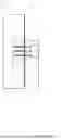
FIG. 1 depict a diagram of fastening system for structural elements for erecting multipurpose industrial buildings according to embodiments of the present invention;
FIG. 2 depicts a diagram of an anchor block during a manufacturing process according to embodiments of the present invention;
FIG. 3A depicts dimensions of the anchor block diagram according to embodiments of the present invention;
FIG. 3B depicts dimensions of the anchor block diagram according to embodiments of the present invention;
FIG. 4 depicts a diagram of fastening system for multiple structural elements for erecting multipurpose industrial buildings according to embodiments of the present invention; and
FIG. 5 depicts a diagram of a method for fastening structural elements for erecting multipurpose industrial buildings according to embodiments of the present invention.
DETAILED DESCRIPTION
Reference to “a specific embodiment” or a similar expression in the specification means that specific features, structures, or characteristics described in the specific embodiments are included in at least one specific embodiment of the present invention. Hence, the wording “in a specific embodiment” or a similar expression in this specification does not necessarily refer to the same specific embodiment.
Hereinafter, various embodiments of the present invention will be described in more detail with reference to the accompanying drawings. Nevertheless, it should be understood that the present invention could be modified by those skilled in the art in accordance with the following description to achieve the excellent results of the present invention. Therefore, the following description shall be considered as a pervasive and explanatory description related to the present invention for those skilled in the art, not intended to limit the claims of the present invention.
Reference to “an embodiment,” “a certain embodiment” or a similar expression in the specification means that related features, structures, or characteristics described in the embodiment are included in at least one embodiment of the present invention. Hence, the wording “in an embodiment,” “in a certain embodiment” or a similar expression in this specification does not necessarily refer to the same specific embodiment.
Generally, the construction material of choice for modern industrial structures is concrete. Concrete is a durable material, and readily available around the world. It can be used to form walls and columns of the industrial building. Conventional cast-in-place concrete construction relies on the use of labor-intensive, time-consuming, built-in-place formwork that must be erected for each wall panel. The formwork takes up space that could be used for moving around the site and is a time-consuming process.
Given the time-consuming nature of cast-in-place concrete, the concept of casting off-site arose, with the pre-cast concrete pieces then being assembled on-site. While moving the slow and time-consuming process of pouring concrete and waiting for cure, to an off-site location, does speed up the process of construction, the resulting structure lacks the strength of a cast-in-place building due to weak connectivity.
The present invention solves the foregoing issues by providing a fastening system that allows connecting concrete structural elements to ensure structural stability and integrity.
More specifically, embodiment of the fastening system for a reinforced column and a concrete composite wall panel used in a construction system for erecting multipurpose industrial buildings from large-unit block are described herein. In particular, according to embodiments of the present invention the system allows joining concrete wall panels to columns using screw assemblies and embedded high-strength polyurethane foam. The system and method for fastening the panels to columns can have liners made of high-strength polyurethane foam, which are installed in the body of the column during its manufacturing, holes provided in the wall panels, which are also made during the manufacturing, and self-tapping screws with a diameter of about ½″.
A column according to embodiment of the present invention can be a monolithic weight-bearing column that includes a vertical reinforced concrete part fully integrated with a foundation footer part. The monolithic weight-bearing column allows its application with various parts of an industrial building and its adaptation to various parameters and requirements of the different installation positions of the industrial building.
A wall panel according to embodiments of the present invention can be provided with two thin layers of reinforced concrete with a thermal insulation layer between them connected to each other by fiberglass connections. In addition, a reinforced mesh to ensure rigidity of the wall panel can also be provided. The construction and method of manufacture of the wall panel with an energy-efficient insulation allows its application in erecting multipurpose industrial buildings with the controlled indoor environment.
The present invention solves the foregoing issues by providing a fastening system 100, illustrated in FIGS. 1-4, for connecting concrete structural elements to ensure structural stability and integrity. The fastening system 100 allows to avoid using difficult and costly welding process on the construction site and achieve high level of accuracy during fastening of the structural components without imposing strict accuracy requirements thereby achieving low-cost industrial building construction solutions.
FIG. 1 shows the fastening system 100 being provided with a column 10. The column 10 can be provided with an anchor block 13 incorporated within the column 10 during the manufacturing process, for example, as shown in FIG. 2. According to embodiments of the present invention, the column 10 can be a reinforced-concrete column integrated with a foundation footer by a single piece reinforcement structural frame (as shown in FIG. 4). The column 10 is preferable made from high strength concrete, preferably, about 8000 pound per square inch (psi). The anchor block 13 can be made from a high-strength polyurethane foam.
FIGS. 3A and 3B show the preferred dimensions of the anchor block 13 according to embodiment of the present inventions. The anchor block 13 can have a trapezoid shape. In particular, a first portion “A” can be about 4 ¾″, each side portions “B” can be about 9 ½″, a second portion “C” can be about 9 ½″. The width of the anchor block 13 can be about 2″. In a preferred embodiment of the present invention, there are multiple anchor blocks 13 embedded into the column 10 (as shown in FIG. 4).
Turning back to FIG. 1, the fastening system 100 can be provided with a plurality of screws 17 for fastening a wall panel 15 to the column 10 (as shown in FIGS. 1 and 4). The wall panel 15 can be provided with a cavity 12. The screws 17 can be self-tapping screws with a ½″ diameter. Preferably, three screws 17 are used per single anchor block 13.
The wall panel 15 is preferably be provided with two thin layers of reinforced concrete with effective thermal insulation between them connected to each other by fiberglass connections. The reinforced concrete can have a compression strength of 8000 psi. The wall panel 15 can have a length from 5 feet to 31 feet depending on the industrial building size being assembled. The height of the wall panel 15 can be from 5 feet to 17 feet depending on the industrial building size being assembled.
FIG. 5 illustrates a method 200 for fastening the wall panel 10 to column 10 at the construction site according to the embodiments of the present invention. An initial step 210 is to provide the wall panel 15 with the cavity 12. The next step 220 is for providing the column 10 with the anchor block 13. Then, in a step 225 the cavity 12 of the wall panel 15 is aligned with the anchor block 13 of the column 10. A final step 230 provides for fastening the wall panel 15 to the column 10 by inserting a plurality of self-tapping screws 17 through the cavity 12 in the wall panels 15 into the anchor block 13.
As illustrated in FIG. 4, the fastening system 100 can include multiple columns 10 that can fasten to a single or multiple wall panels 15. In other words, for example, two columns 10 can be positioned on each side of the wall panel 15, and the wall panel 15 is fastened to two columns 10 on each side of the wall panel 15. Additionally, multiple wall panels 15 can be fastened to the same two columns 10. In this instance, plurality of cavities 12 and multiple anchor blocks 13 are provided. The fastening system 100 can withhold load force of about 145 kilonewtons (kN).
The foregoing detailed description of the embodiments is used to further clearly describe the features and spirit of the present invention. The foregoing description for each embodiment is not intended to limit the scope of the present invention. For example, the fastening system according to the present invention can be used with other structural elements other than columns and wall panels described here. Moreover, all kinds of modifications made to the foregoing embodiments and equivalent arrangements should fall within the protected scope of the present invention. Hence, the scope of the present invention should be explained most widely according to the claims described thereafter in connection with the detailed description, and should cover all the possibly equivalent variations and equivalent arrangements.
The terminology used herein is for the purpose of describing particular embodiments only and is not intended to be limiting of the present invention. As used herein, the singular forms “a”, “an” and “the” are intended to include the plural forms as well, unless the context clearly indicates otherwise. It will be further understood that the terms “comprises” and/or “comprising,” when used in this specification, specify the presence of stated features, integers, steps, operations, elements, and/or components, but do not preclude the presence or addition of one or more other features, integers, steps, operations, element components, and/or groups thereof.
The corresponding structures, materials, acts, and equivalents of all means or step plus function elements in the claims below are intended to include any structure, material, or act for performing the function in combination with other claimed elements as specifically claimed. The description of the present invention has been presented for purposes of illustration and description, but is not intended to be exhaustive or limited to the invention in the form described. Many modifications and variations will be apparent to those of ordinary skill in the art without departing from the scope and spirit of the invention. The embodiment was chosen and described in order to best explain the principles of the invention and the practical application, and to enable others of ordinary skill in the art to understand the invention for various embodiments with various modifications as are suited to the particular use contemplated.
Claims
What is claimed is:1. A method for fastening structural elements for erecting multipurpose industrial buildings, the method comprising:
providing a first structural element with a cavity;
providing a second structural element having an anchor block;
aligning the cavity of the first structural element with the anchor block of the second structural element;
fastening the first structural element to the second structural element by inserting a plurality of screws through the cavity into the anchor block.
2. The method according to claim 1, wherein the first structural element is a wall panel comprising:
two layers of reinforced concrete with a thermal insulation layer between the two layers of reinforced concrete connected to each other by fiberglass connections.
3. The method according to claim 1, wherein the second structural element is a reinforced-concrete column comprising a foundation footer.
4. The method according to claim 3, wherein the anchor block is made from a high-strength polyurethane foam.
5. The method according to claim 1, wherein the screws of the plurality of screws are self-tapping screws with a screw diameter of about ½″.
6. The method according to claim 1, wherein the first structural element comprises a plurality of wall panels; and
the second structural element comprises a plurality of columns.
7. The method according to claim 3, wherein a strength of concrete of the reinforced-concrete column is about 8000 pound per square inch (psi).
8. A fastening system for structural elements for erecting multipurpose industrial buildings, the system comprising:
a first structural element with a cavity;
a second structural element having an anchor block, the cavity of the first structural element is configured to be aligned with the anchor block of the second structural element; and
a plurality of screws configured to be inserted through the cavity into the anchor block thereby fastening the first structural element to the second structural element.
9. The fastening system according to claim 8, wherein the first structural element is a wall panel comprising:
two layers of reinforced concrete with a thermal insulation layer between the two layers of reinforced concrete connected to each other by fiberglass connections.
10. The fastening system according to claim 8, wherein the second structural element is a reinforced-concrete column comprising a foundation footer.
11. The fastening system according to claim 8, wherein the anchor block is made from a high-strength polyurethane foam.
12. The fastening system according to claim 8, wherein the first structural element comprises a plurality of wall panels; and
the second structural element comprises a plurality of columns.
13. The fastening system according to claim 8 configured to withhold a load force of about 145 kilonewtons (kN).
Images & Drawings included:


Sources:
- United States Patent and Trademark Office - verify current appl. status at the USPTO↗
Similar patent applications:
- » 20230166828
UAV structural elements quick release fastening system - » 20110154750
Fastening system for a plate-shaped structural element - » 20070284479
QUICK-CHANGE FASTENING SYSTEM FOR MOUNTING AN ELEMENT TO A FASTENING STRUCTURE - » 20100200696
Quick-change fastening system for mounting an element to a fastening structure - » 20240102503
FASTENING DEVICE FOR FASTENING A MECHANICAL ELEMENT WITH A SUPPORT STRUCTURE AS WELL AS FASTENING SYSTEM - » 20090221154
Fastening system for fastening a cabin fitting element to a support structure of an aircraft - » 20070068090
Coordinated system for removeable fastening of furniture elements to the bearing structure of a prefabricated wall - » 20250347306
A FASTENER ELEMENT, A TOOL AND A FASTENER SYSTEM FOR FASTENING BOARDS TO A FRAME STRUCTURE - » 20170107098
Microelectromechanical system and fabricating process having decoupling structure that includes attaching element for fastening to carrier - » 9639870
System and method of generating a finite element mesh for a threaded fastener and joining structure assembly
Recent applications in this class:
- » 20260078574 2026-03-19
Design and Production of building structures and infrastructures using dimensionally predetermined adaptable socket array systems - » 20250347101 2025-11-13
METHOD AND ARRANGEMENT FOR COUPLING VERTICAL PRECAST STRUCTURES - » 20250341087 2025-11-06
CONDUCTIVE CONCRETE COMPOSITIONS FOR INFRASTRUCTURE APPLICATIONS - » 20250341086 2025-11-06
CONDUCTIVE CONCRETE COMPOSITIONS FOR INFRASTRUCTURE APPLICATIONS - » 20250333948 2025-10-30
Ultrathin, pre-stressed, concrete component system - » 20250305269 2025-10-02
METHOD AND ARRANGEMENT FOR INTERCONNECTING HORIZONTAL PRECAST STRUCTURES - » 20250257559 2025-08-14
RAILING SYSTEM AND METHOD OF USE THEREOF - » 20250243658 2025-07-31
METHODS OF FORMING CONNECTIONS BETWEEN CONCRETE ARTICLES - » 20240229444 2024-07-11
FABRICATED CONCRETE CONNECTION STRUCTURE AND CONSTRUCTION METHOD - » 20240209617 2024-06-27
STRUCTURAL LAMINATED FIBER-REINFORCED CEMENT BEAMS AND COLUMNS