TWO-PIECE, SPLIT BACKUP SHOE FOR PACKER ASSEMBLIES
US20260146508A1
2026-05-28
18/961,758
2024-11-27
Smart Summary: A new type of backup shoe is designed for use in packer assemblies, which help keep seals tight in wells. It consists of two separate pieces that can move independently. One piece has a flange and is flexible, allowing for a better seal without the sealing element pushing out. The other piece has a tail and provides strength to prevent damage during use. This design aims to improve the effectiveness and reliability of the packer system. 🚀 TL;DR
Abstract:
Backup shoes can be included in a packer assembly to retain a sealing element in sealing engagement with an inside of casing, tubing string, or wellbore wall. The backup shoes are split into two separate pieces along a split line. A first piece includes a flange without a tail, and a second piece includes a tail without a flange. The two pieces have independent movement from each other during setting of the packer. The first piece can have improved flexibility to provide a better seal without the sealing element extruding over the flange. The second piece can provide the strength necessary to prevent shearing of the backup shoes, which could result in failure of the packer.
Inventors:
- Frank Vinicia Acosta Villarreal 18 🇺🇸 Houston, TX, United States
- Xiaoguang Allan Zhong 29 🇸🇬 Singapore, Singapore
- Shobeir Pirayeh Gar 6 🇺🇸 Plano, TX, United States
Assignee:
- HALLIBURTON ENERGY SERVICES, INC. 10,733 🇺🇸 Houston, TX, United States
Applicant:
Interested in similar patents?
Get notified when new applications in this technology area are published.
Classification:
E21B33/1216 » CPC main
Sealing or packing boreholes or wells in the borehole; Packers; Plugs characterised by the construction of the sealing or packing means Anti-extrusion means, e.g. means to prevent cold flow of rubber packing
E21B33/12 IPC
Sealing or packing boreholes or wells in the borehole Packers; Plugs
Description
TECHNICAL FIELD
A packer assembly having a two-piece, split backup shoe is provided. The split backup shoe includes a first piece having a flange portion and a second piece having a tail portion.
BRIEF DESCRIPTION OF THE FIGURES
The features and advantages of certain embodiments will be more readily appreciated when considered in conjunction with the accompanying figures. The figures are not to be construed as limiting any of the embodiments.
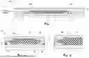
FIG. 1 is a cross-sectional view of packer assembly according to certain embodiments.
FIG. 2A is a cross-sectional view of the packer assembly showing a backup shoe engaging with a sealing element as the packer assembly is being set.
FIG. 2B is a cross-sectional view of the backup shoe of FIG. 2A showing notching of the sealing element after setting.
FIG. 3A is a cross-sectional view of a two-piece, split backup shoe showing the two pieces being separated according to certain embodiments.
FIG. 3B is a cross-sectional view of the two-piece, split backup shoe of FIG. 3A showing the two pieces abutting each other.
FIG. 4A is a cross-sectional view of a two-piece, split backup shoe showing the two pieces being separated according to certain other embodiments.
FIG. 4B is a cross-sectional view of the two-piece, split backup shoe of FIG. 4A showing the two pieces abutting each other.
FIG. 5A is a cross-sectional view of the two-piece, split backup shoe of FIG. 3B during the setting process.
FIG. 5B is a cross-sectional view of the backup shoe of FIG. 5A after the setting process.
FIG. 6A is a cross-sectional view of the two-piece, split backup shoe of FIG. 3B further including an anti-extrusion ring.
FIG. 6B is an enlarged view of the backup shoe of FIG. 6A showing a potential shear plane.
FIG. 7A is a cross-sectional view of the two-piece, split backup shoe of FIG. 3B further including a toe support and arrows showing movement of the two pieces during setting.
FIG. 7B is a cross-sectional view of the backup shoe of FIG. 7A after setting.
FIG. 8A is a cross-sectional view of the two-piece, split backup shoe of FIG. 4B further including a toe support and arrows showing movement of the two pieces during setting.
FIG. 8B is a cross-sectional view of the backup shoe of FIG. 8A after setting.
DETAILED DESCRIPTION OF THE INVENTION
Oil and gas hydrocarbons are naturally occurring in some subterranean formations. In the oil and gas industry, a subterranean formation containing oil and/or gas is referred to as a reservoir. A reservoir can be located under land or offshore. Reservoirs are typically located in the range of a few hundred feet (shallow reservoirs) to a few tens of thousands of feet (ultra-deep reservoirs). In order to produce oil or gas, a wellbore is drilled into a reservoir or adjacent to a reservoir. The oil, gas, or water produced from a reservoir is called a reservoir fluid.
As used herein, a “fluid” is a substance having a continuous phase that can flow and conform to the outline of its container when the substance is tested at a temperature of 71° F. (22° C.) and a pressure of one atmosphere “atm” (0.1 megapascals “MPa”). A fluid can be a liquid or gas. A homogenous fluid has only one phase, whereas a heterogeneous fluid has more than one distinct phase.
A well can include, without limitation, an oil, gas, or water production well, an injection well, or a geothermal well. As used herein, a “well” includes at least one wellbore. A wellbore can include vertical, inclined, and horizontal portions, and it can be straight, curved, or branched. As used herein, the term “wellbore” includes any cased, and any uncased, open-hole portion of the wellbore. A near-wellbore region is the subterranean material and rock of the subterranean formation surrounding the wellbore. As used herein, a “well” also includes the near-wellbore region. The near-wellbore region is generally considered to be the region within approximately 100 feet radially of the wellbore. As used herein, “into a subterranean formation” means and includes into any portion of the well, including into the wellbore, into the near-wellbore region via the wellbore, or into the subterranean formation via the wellbore.
A portion of a wellbore can be an open hole or a cased hole. In an open-hole wellbore portion, a tubing string can be placed into the wellbore. The tubing string allows fluids to be introduced into or flowed from a remote portion of the wellbore. In a cased-hole wellbore portion, a casing is placed into the wellbore that can also contain a tubing string. A wellbore can contain an annulus. Examples of an annulus include but are not limited to the space between the wellbore and the outside of a tubing string in an open-hole wellbore; the space between the wellbore and the outside of a casing in a cased-hole wellbore; and the space between the inside of a casing and the outside of a tubing string in a cased-hole wellbore.
During well completion, it is commonly desired to seal a portion of an annulus so fluids will not flow through the annulus but rather flow through the tubing string or casing. By sealing the portion of the annulus, oil, gas, water, or combinations thereof can be produced in a controlled manner through the wellhead via the tubing string or casing. Different downhole tools can be used to create seals in the well. Examples of such tools include packer assemblies.
Packer assemblies can be utilized to seal the annulus in a wellbore. Typically, packers are used to anchor the tubing to the wellbore and to seal the tubing to the wellbore. A packer can be used in cased wellbore portions or open-hole wellbore portions. A packer can include a sealing element that seals to the wellbore to isolate the portion of the wellbore and can also include slips that grip the inside of a casing or wall of the wellbore to anchor the packer to the casing or wellbore wall. Most sealing elements are made from an elastomer material that is capable of elastically stretching and can impart structural integrity to the seal created. The sealing element is a ring of the elastomeric material with the entirety of the inner diameter of the sealing element fitted onto the outside of a mandrel. The sealing element is generally constrained on the outside of the edges such that actuation of the packer axially squeezes the sealing element to cause radial expansion of the sealing element and seals the annulus. Backup shoes can be used to constrain the outside edges of the sealing elements.
A packer can be introduced into or run into the wellbore on a work string or on a production tubing during the course of treating and preparing the well for production. As used herein, the terms “run into” and “run-in” mean the time during which the packer assembly is being introduced into a wellbore to a desired location. The packer can act as an isolation device. For example, the packer can be used to substantially seal the annulus between the outside of the production tubing and the inside of the casing or wall of the wellbore by blocking the movement of fluids through the annulus past the packer location. Packers can also be used as service tools.
After the packer assembly has been run into the desired location in the wellbore, the packer can be set. As used herein, the term “set,” and all grammatical variations thereof, means the act of causing the packer assembly to be permanently or retrievably fixed at a desired location within a tubing string. Setting generally involves movement of one or more tool components, such as a setting tool, that applies compressive force to the packer which causes the sealing element to buckle and radially deform to contact and engage with an inner diameter of the tubing string, casing string, or wellbore wall as well as maintaining a seal against an outer diameter of a mandrel. Packer sealing elements can be mechanically set, hydraulically set, or hydrostatically set. Mechanical actuation uses a setting tool to apply the axial compressive force needed to deploy the sealing element. A hydraulic packer has an internal setting piston that is hydraulically actuated to apply the compression needed to energize the sealing element. A hydrostatic set packer has an atmospheric chamber that collapses with well hydrostatic pressure to supply the compressive forces needed to set the packer.
FIG. 1 shows a packer assembly 10 according to certain embodiments. The packer assembly 10 includes a mandrel 12 with a sealing element 17 disposed around the outer diameter 13 of the mandrel 12. A movable ramp 14 and a fixed ramp 15 (or stationary ramp) are also located around the outer diameter 13 of the mandrel 12 with the sealing element 17 disposed between. O-rings 16 can be located around the outside of the mandrel 12 and underneath a portion of the movable ramp 14 and fixed ramp 15. A cover sleeve 18 can be located on top of the movable ramp 14 and fixed ramp 15. Backup shoes 100 can be located on top of the movable ramp 14 and the fixed ramp 15 and between the ends of the sealing element 17 and inside edges of the cover sleeve 18. During and after setting, the sealing element 17 can engage with an inner diameter of a casing 11 to form a seal in the wellbore, for example as shown in FIG. 2A as the packer is being set. Although shown in the drawings as a casing, it is to be understood that the seal created can also be made with an inner diameter of a tubing string or a wellbore wall without the need to continually refer to the alternatives throughout.
The backup shoes 100 are an integral part of the packer assembly and supports the sealing element 17 during and after setting. A setting force can be applied to the movable ramp 14 in a direction towards the fixed ramp 15 and causes the movable ramp 14 move towards the fixed ramp 15. With the fixed ramp 15 being stationary, the angled portions of the movable ramp 14 and fixed ramp 15 can move underneath the angled portions of the sealing element 17 and force the sealing element 17 to radially expand out towards and into engagement with the inner diameter of the casing 11 as shown in FIG. 2A. The deployment of the sealing element 17 can also cause it to push the backup shoes 100 and the cover sleeve 18, leading to deployment of the backup shoes 100 and shearing of a pin holding the cover sleeve 18.
The backup shoes 100 need to have a sufficient strength after setting to constrain the set sealing element and withstand pressure differentials applied to the packer element from wellbore fluids and fluids pumped into the wellbore without a portion of the backup shoe shearing or breaking. Without enough strength during and after setting, the backup shoe can fold back on itself, which is called a flexural failure, or it may face shear failure close to the outer diameter of the cover sleeve; and there can also be extrusion of the sealing element over the shoes, which can cause failure of the seal. This results in a failed seal, and the packer assembly may need to be replaced with a new packer assembly. Moreover, if the strength of the backup shoe is selected to be capable of withstanding large pressure differentials, then the backup shoe may be too stiff, which can result in a delay of the shoe deployment and increase the chance of notching of the sealing element during the setting and allow part of the sealing element to extrude over the top of the backup shoe and into a space 19, for example as shown in FIG. 2B.
The backup shoes 100 also need to have enough flexibility to deploy in-phase with the sealing element 17 during the setting process. The strength and flexibility of backup shoes is highly, inversely correlated. With an increase in strength, the flexibility decreases; and with an increase in flexibility, the strength decreases. For example, in order to make a backup shoe more flexible, then the thickness of some portions of the shoe can be decreased, which reduces the overall strength and can introduce a potential shear problem, result in a lower shear rating than needed, and can also allow setting of the packer to begin prematurely.
Current backup shoes are made as a single piece unit. One significant disadvantage to current designs is there is oftentimes a tradeoff where flexibility is sacrificed to increase the strength, so the seal is maintained, or where the strength is sacrificed to increase the flexibility. Accordingly, a single-piece backup shoe may not have both—the targeted strength and the targeted flexibility. As discussed above, if the strength is too great, then there is a risk that the backup shoe will punch through the element during the setting and create rubber nibbling. However, then the backup shoe may not have enough flexibility to engage with the casing ID to contain the sealing element. One way to overcome the problems associated with this tradeoff is to place 2 backup shoes next to each other, called a double-layer backup shoe. However, there are problems associated with a double-layer backup shoe. One such problem is the increased costs related to having 4 total, complete backup shoes as part of the packer assembly instead of just 2. Another problem is components of the packer assembly, for example, the mandrel, may need to be adjusted to accommodate the additional space that the extra backup shoes take up. This can necessitate increasing the length of the mandrel and/or other components of the packer assembly such as the ramps. Another problem is the double-layer backup shoes may lift up and away from the mandrel OD, which can cause extrusion of the sealing element at the mandrel OD. Another problem from mechanical standpoint, is the double-layer backup shoes may not achieve the target strength-flexibility balance when an extrusion gap (which is located between the ID of the casing and the OD of the sealing element before setting) increases. In other words, as the extrusion gap increases, achieving both the target strength and flexibility concurrently becomes very challenging, hence the effectiveness of double-layer backup shoe concept starts to decline. Thus, there is a long-felt need for improved backup shoes that solve the aforementioned problems.
It has been discovered that a backup shoe can be split into two separate pieces. Splitting the backup shoe into two pieces—one piece having a flange without tail and the other piece having a tail without flange—provides a better balance between strength and flexibility of the shoe. That is, the backup shoe is more flexible when being set without sacrificing the strength needed to hold the differential pressure compared to current backup shoes that are made as a single piece.
It is to be understood that the discussion of any of the embodiments regarding the plug is intended to apply to all of the method and apparatus embodiments without the need to repeat the various embodiments throughout. Any reference to the unit “gallons” means U.S. gallons.
The methods can include introducing a packer assembly 10 into a portion of a wellbore. The packer assembly 10 can be in a run-in position during introduction, for example, as shown and described above with reference to FIG. 1. As used herein, the terms “run into” and “run in” mean the packer assembly 10 is capable of being moved within a tubing string, casing string, or the wellbore to a desired location and/or the time during which the packer assembly 10 is being introduced into a wellbore at a desired location.
The methods can also include setting the packer assembly 10 after introduction. Setting of the packer assembly 10 can involve causing the outer diameter (OD) of the sealing element 17 to expand radially away from the mandrel 12 to form a pressure tight annular seal, for example as shown in FIGS. 2A, 5B, and 6A. The OD of the sealing element 17 can radially expand outwardly away from the mandrel 12 to engage with an inner diameter (ID) of the tubing string or casing 11 or a wellbore wall when the packer assembly 10 is set. It is to be understood that although reference is made to a casing 11, the packer assembly 10 can be used to create a seal in a tubing string or wellbore wall. Accordingly, any reference to a casing 11 also includes a tubing string or wellbore wall. As described above, the setting tool can cause movement of the cover sleeve 18 and cause the sealing element 17 to form the annular seal. Engagement of the sealing element 17 can restrict fluid flow past the sealing element.
The packer assembly 10 also includes a first backup shoe 100 and a second backup shoe 100, for example as shown in FIG. 1. The first backup shoe 100 is located adjacent to a first end of the sealing element 17, for example at or near the location of the movable ramp 14; and the second backup shoe 100 is located adjacent to a second end of the sealing element 17, for example at or near the location of the fixed ramp 15. Each of the backup shoes 100 include a first piece 110 and a second piece 120. The first piece 110 and the second piece 120 are separable from each other. The backup shoes 100 can be made from a variety of materials, for example, metals or metal alloys. The first pieces 110 and the second pieces 120 can be made from the same or different materials. For example, ductile steel (annealed) 35 kilopounds per square inch “ksi” can be used for the first pieces 110, and a higher yield material (e.g., 60 ksi, 80 ksi, or 110 ksi) can be used for the second pieces 120.
FIG. 3A shows the backup shoes 100 according to any of the embodiments with the first piece 110 being separated from the second piece 120, while FIG. 3B shows the first and second pieces 110/120 abutting each other as they would be when assembled onto the packer assembly 10 and during run in. FIG. 4A shows the backup shoes 100 according to other embodiments with the first piece 110 being separated from the second piece 120, while FIG. 4B shows the first and second pieces 110/120 abutting each other as they would be when assembled onto the packer assembly 10 and during run in. It is to be understood that the drawings depict a first backup shoe 100 that can be located near the movable ramp 14, the second backup shoe 100 would be the mirror image (i.e., the drawing would be rotated 180°) of the first backup shoe 100 without the need to repeat the various embodiments in relation to the mirror image of the first backup shoe. The first pieces 110 and the second pieces 120 are just in contact with each other without a mechanical connection (e.g., without being welded or spot welded together). For assembly purposes onto the packer assembly 10, a temporary weak connection can be made using glue or an epoxy so the first and second pieces abut each other.
The first pieces 110 include a flange 111. The first pieces 110 also include a vertical portion 112. As shown in FIGS. 3A, 3B, 5A, and 5B, the flange 111 can extend away from the vertical portion 112 and terminate at an end. The flange 111 can have the same thickness or the thickness can taper down from the vertical portion 112 to the end as shown. The vertical portion 112 can extend down from the flange 111 towards the movable ramp 14 or fixed ramp 15. The vertical portion 112 can have a thickness T1. The thickness of the flange 111 and the thickness T1 of the vertical portion 112 can be selected such that the first pieces 110 have a targeted flexibility. The vertical portion 112 includes an inside edge 113 and an outside edge 114. The lower portion of the flange 111, which is the portion located closer to the mandrel 12, and the outside edge 114 of the vertical portion 112 are located next to the edges of the sealing element 17 and constrain the edges of the sealing element 17 during and after setting.
The second pieces 120 include a tail 121. The second pieces 120 also include a vertical portion 122. FIGS. 3A, 3B, 5A, and 5B show the tail 121 extending away from the vertical portion 122 and terminated at an end according to any of the embodiments. FIGS. 4A and 4B show the tail 121 curving underneath the vertical portion 112 of the first pieces 110 and terminated at an end according to other embodiments. According to any of the embodiments, the tail 121 can have the same thickness or the thickness can taper down from the vertical portion 122 to the end. The vertical portion 122 can extend up from the tail 121 towards the inside of a tubing string, casing 11, or wellbore wall. The vertical portion 122 can have a thickness T2. The thickness of the tail 121 and the thickness T2 of the vertical portion 122 can be selected such that the second pieces 120 have a targeted strength. The vertical portion 122 includes an inside edge 123 and an outside edge 124.
The backup shoes 100 are a single shoe that has two separate pieces (i.e., the first piece 110 and the second piece 120). The single shoe can be split into the two, separate pieces along a split line 130. FIGS. 3A and 4A show the split line 130 when the first pieces 110 are separated from the second pieces 120; and FIGS. 3B and 4B show the split line 130 when the first pieces 110 abut the second pieces 120. The backup shoes 100 can be made as a single piece construction and then cut, for example via a laser cut, along the split line 130 to form the two pieces. When the backup shoes are made from a single piece construction and then cut into two separate pieces, the angles of the inside edge 113 of the first pieces 110 and the angles of the inside edge 123 of the second pieces 120 will inherently match each other. According to other embodiments, the first pieces 110 and the second pieces 120 can each be made separately and then assembled onto the packer assembly 10 where they will abut each other. When the first and second pieces 110/120 are made separately, the angles of both inside edges 113/123 should match. This ensures that when the two pieces are assembled onto the packer assembly 10, then there are no gaps or spaces between the inside edges 113/123.
The split line 130 can be located equidistant from the outside edge 114 of the first piece 110 and the outside edge 124 of the second piece 120 and extend down the vertical portions 112/122. According to these embodiments, the thickness T1 of the vertical portion 112 of the first piece 110 will be the same as or substantially the same as (i.e., within +/−10%) the thickness T2 of the vertical portion 122 of the second piece 120. The split line 130 can also be located closer to the outside edge 114 of the first piece 110 or closer to the outside edge 124 of the second piece 120. According to these embodiments, the thickness T1 of the vertical portion 112 of the first piece 110 can be less than or greater than the thickness T2 of the vertical portion 122 of the second piece 120. The thickness T1 of the vertical portion 112 of the first piece 110 and the thickness T2 of the vertical portion 122 of the second piece 120 can be selected such that the backup shoe has the targeted flexibility and strength.
FIGS. 5A and 5B show the backup shoes 100 at the beginning of the setting process and close the being fully set, where no signs of a notching or punching of the sealing element is observed. Once the setting load is applied, the first pieces 110 start to plastically deploy in-phase with element buckling while the second pieces 120 plastically rotate to stay upright and held against the cover sleeve 18. At the set and deployed position, the second pieces 120 provide extra shear resistance required to hold large differential pressures without the risk of stress localization in the first pieces 110 at the critical shear plane 115 (shown in FIGS. 6A and 6B) or premature shear failure. Therefore, the backup shoes 100 benefit from both required flexibilities to achieve concurrent deployment with the sealing element 17, while keeping and not compromising the required shear strength to hold pressure differentials. As can be seen, during setting, the flange 111 of the first pieces 110 can bend and angle upwards from the vertical portion 112 and move such that the end of the flange 111 touches the inside of the casing 11. The flange 111 can have more contact with the surface of the inside of the casing 11 compared to current single-piece backup shoes.
As can be seen in FIG. 5B, the tail 121 can be held down by the cover sleeve 18 so the tail 121 maintains contact with the respective ramps 14 or 15 and prevents the second pieces 120 from moving radially away from the ramps. The entire vertical portion 112 and flange 111 can constrain and retain the sealing element 17 into sealing engagement with the inside of the casing 11. The second pieces 120 can move with the first pieces 110 during setting such that the inside edge 113 of the first pieces 110 remain abutted to the inside edge 123 of the second pieces 120. The first pieces 110 and second pieces 120 can have independent movement from each other. One example of such an independent movement is shown in FIG. 5B where a temporary space 19 is created. One significant advantage, and as can be seen in FIG. 5B, the temporary space 19 can be created when a portion of the inside edges 113/123 move away from each other and are no longer abutting each other during the setting process. However, once the packer is fully set, for example as shown in FIG. 6A, the inside edges 113/123 of the vertical portions 112/122 of the first and second pieces 110/120 come back into full contact and the space is closed. In this manner, a necessary structural strength is provided by the second pieces 120 and imparted to the first pieces 110 after setting.
As can be seen in FIG. 6B, the first pieces 110 can have a shear plane 115. The shear plane 115 can be located near the portion of the first pieces 110 where the flange 111 extends away from the vertical portion 112. Without sufficient strength, forces exerted on the backup shoes 100 from wellbore fluids can cause the flange 111 to partially or completely break (or shear) from the vertical portion 112. If this occurs, then the first pieces 110 are no longer capable of retaining the sealing element 17 in a sealing engagement with the inside of the casing 11. However, it has been discovered that the splitting of the backup shoes 100 into two pieces and independent movement decouples the inverse correlation between strength and flexibility, and thus, becomes weakly correlated versus highly correlated as is seen in current designs. Accordingly, the first pieces 110 can be more flexible than current designs without shearing because the second pieces 120 can provide the strength needed to maintain a seal without failure of the backup shoes.
Numerous variations can be made to meet a targeted flexibility and strength. The variations can be determined through analysis of a proposed design. By way of a first example, the thickness of the flange 111 can be decreased to provide increased flexibility. By way of a second example, the split line 130 can be located closer to the outside edge 114 of the first pieces 110 such that the thickness T1 of the vertical portion 112 is decreased to provide increased flexibility. This example will also increase the thickness T2 of the vertical portion 122 of the second pieces 120, which increases the strength provided by the second pieces. By way of a third example, the flange 111 can also taper and have a thicker portion located next to the vertical portion 112 compared to the end of the flange 111. The flange 111 also needs to support the set sealing element 17 without shearing or encountering stress fractures. Therefore, the flange, first pieces, and/or the second pieces can be modified to provide the necessary strength.
The strength of the second pieces 120 can also be modified. By way of a first example, the thickness of the tail 121 can be increased so premature shearing under fluid pressure does not occur. By way of a second example, the thickness T2 of the vertical portion 122 of the second pieces 120 can also be increased, for example by having the split line 130 located closer to the outside edge 114 of the vertical portion 112 of the first pieces 110, which can increase the overall strength of the backup shoes 100.
According to any of the embodiments, the first pieces 110 and the flanges 111 are flexible enough such that the sealing element 17 is fully supported and the flanges prevent extrusion of the sealing element 17 over the top of the flanges. According to any of the embodiments, the second pieces 120 have a strength such that the backup shoes 100 withstand fluid pressures during and after setting. By way of example, the backup shoes may withstand fluid pressures up to 20,000 pounds force per square inch (psi) 137.9 megapascals “MPa”). As used herein, the term “withstand,” and all grammatical variations thereof, means to perform an intended function without failing. Failing can be the result of cracks in portions of the backup shoes or shearing of portions of the backup shoes, whereby the seal created in the wellbore is no longer maintained. If the seal is not maintained, then fluid could undesirably flow past the packer assembly 10. The significant advantage of the split backup shoes being able to meet the targeted flexibility and strength becomes more advantageous and works even better as the extrusion gap increases, which solves the problems of current designs that fail to provide a robust solution.
With reference to FIG. 6A, the packer assembly 10 can further include an anti-extrusion ring 140. The anti-extrusion ring 140 can be located at a bottom of the vertical portion 122 of the second pieces 120 adjacent to the inside edge 123 and tail 121. If a portion of the tail 121 and vertical portion 122 move away from the respective ramps 14 or 15, then the anti-extrusion ring 140 can limit or prevent some of the sealing element 17 from extruding between the underneath of the vertical portion 122 and the ramps. The anti-extrusion ring 140 can be made of a variety of materials, such as but not excluding, plastic, wire mesh, or polytetrafluoroethylene sold under the tradename Teflon®. However, the anti-extrusion ring 140 may not be needed like current designs do because by being two, separate pieces, the first piece 110 is unlikely to lift up the second piece 120 during setting, which reduces or prevents extrusion at the sealing element 17.
Turning now to FIGS. 7A-8B , the backup shoes 100 can further include a toe support 150. The toe support 150 can be located at a bottom of the vertical portion 112 of the first pieces 110 and can be formed by a second split line 130. The second split line 130 can form an angle with the first, vertical split line 130. The angle can be in a range of 85° to 95°, preferably at an angle of 90°. The toe support 150 can be used in lieu of the anti-extrusion ring 140. During setting, the flange 111 and first piece 110 start to move upwards and into engagement with the ID of the casing 11, which naturally causes the first piece to rotate up and back towards the cover sleeve 18. This upward movement and rotation cause the bottom of the vertical portion 112 to push down on the toe support 150 towards the ramp and forces the tail 121 to remain in contact with the ramps 14/15 thereby preventing extrusion of the sealing element 17. The height of the toe support 150 as well as the angle can be selected such that the tail 121 maintains contact with the ramps and extrusion of the sealing element 17 is substantially inhibited or prevented.
The methods can further include fracturing a portion of a subterranean formation that is penetrated by the wellbore. The step of fracturing can include introducing a fracturing fluid into a zone of the formation, wherein the fracturing fluid creates or enhances a fracture in the formation. The methods can further include producing a reservoir fluid from the subterranean formation that is penetrated by the wellbore.
An embodiment of the present disclosure is a packer assembly comprising: a mandrel; a sealing element located circumferentially around the mandrel; and a first backup shoe located adjacent to a first end of the sealing element, and a second backup shoe located adjacent to a second end of the sealing element, wherein each of the first and second backup shoes comprise: a first piece comprising a flange; and a second piece comprising a tail, wherein the first piece and the second piece are separable from each other. Optionally, the packer assembly further comprises a movable ramp and a fixed ramp, wherein the first backup shoe is located at or near a location of the movable ramp, and wherein the second backup shoe is located at or near a location of the fixed ramp. Optionally, the first pieces further comprise a vertical portion, and wherein the flange extends away from the vertical portion and terminates at an end. Optionally, the vertical portion has a thickness such that a targeted flexibility is achieved. Optionally, the flange has a thickness or a median thickness such that a targeted flexibility is achieved. Optionally, the second pieces further comprise a vertical portion, and wherein the tail extends away from the vertical portion and terminates at an end. Optionally, the vertical portion has a thickness such that a targeted strength is achieved. Optionally, the tail has a thickness or a median thickness such that a targeted strength is achieved. Optionally, the tail curves underneath a vertical portion of the first pieces and terminates at an end. Optionally, the backup shoes are split into the first piece and the second piece along a split line that extends down between vertical portions of the first and second pieces. Optionally, the split line is located equidistant from an outside edge of the first piece and an outside edge of the second piece. Optionally, the split line is located closer to an outside edge of the first piece than an outside edge of the second piece, and wherein a thickness of the vertical portion of the first piece is less than a thickness of the vertical portion of the second piece. Optionally, a thickness of the vertical portion of the first piece and a thickness of the vertical portion of the second piece are selected such that an end of the flange engages with an inner diameter of a casing string, tubing string, or wellbore wall, and the backup shoes have a targeted strength. Optionally, the first piece and the second piece have independent movement from each other during setting. Optionally, the first piece and the flange have a flexibility to prevent extrusion of the sealing element over the top of the flange. Optionally, the second pieces have a strength such that the backup shoes withstand fluid pressures up to 20,000 pounds force per square inch (137.9 megapascals). Optionally, the packer assembly further comprises an anti-extrusion ring, and wherein the anti-extrusion ring is located at a bottom of, and adjacent to, a vertical portion of the second piece and the tail. Optionally, the backup shoes further comprise a toe support, and wherein the toe support is located at a bottom of a vertical portion of the first pieces and formed by a second split line.
Another embodiment of the present disclosure is a method of restricting fluid flow through a portion of a wellbore comprising: (I) introducing a packer assembly into the portion of the wellbore, wherein the packer assembly comprises: (A) a mandrel; (B) a sealing element located circumferentially around the mandrel; (C) a first backup shoe located adjacent to a first end of the sealing element; and (D) a second backup shoe located adjacent to a second end of the sealing element, wherein each of the first and second backup shoes comprise: (i) a first piece comprising a flange; and (ii) a second piece comprising a tail, wherein the first piece and the second piece are separable from each other; and (II) setting the packer assembly after introduction. Optionally, the packer assembly further comprises a movable ramp and a fixed ramp, wherein the first backup shoe is located at or near a location of the movable ramp, and wherein the second backup shoe is located at or near a location of the fixed ramp. Optionally, the first pieces further comprise a vertical portion, and wherein the flange extends away from the vertical portion and terminates at an end. Optionally, the vertical portion has a thickness such that a targeted flexibility is achieved. Optionally, the flange has a thickness or a median thickness such that a targeted flexibility is achieved. Optionally, the second pieces further comprise a vertical portion, and wherein the tail extends away from the vertical portion and terminates at an end. Optionally, the vertical portion has a thickness such that a targeted strength is achieved. Optionally, the tail has a thickness or a median thickness such that a targeted strength is achieved. Optionally, the tail curves underneath a vertical portion of the first pieces and terminates at an end. Optionally, the backup shoes are split into the first piece and the second piece along a split line that extends down between vertical portions of the first and second pieces. Optionally, the split line is located equidistant from an outside edge of the first piece and an outside edge of the second piece. Optionally, the split line is located closer to an outside edge of the first piece than an outside edge of the second piece, and wherein a thickness of the vertical portion of the first piece is less than a thickness of the vertical portion of the second piece. Optionally, a thickness of the vertical portion of the first piece and a thickness of the vertical portion of the second piece are selected such that an end of the flange engages with an inner diameter of a casing string, tubing string, or wellbore wall, and the backup shoes have a targeted strength. Optionally, the first piece and the second piece have independent movement from each other during setting. Optionally, the first piece and the flange have a flexibility to prevent extrusion of the sealing element over the top of the flange. Optionally, the second pieces have a strength such that the backup shoes withstand fluid pressures up to 20,000 pounds force per square inch (137.9 megapascals). Optionally, the packer assembly further comprises an anti-extrusion ring, and wherein the anti-extrusion ring is located at a bottom of, and adjacent to, a vertical portion of the second piece and the tail. Optionally, the backup shoes further comprise a toe support, and wherein the toe support is located at a bottom of a vertical portion of the first pieces and formed by a second split line.
Therefore, the various embodiments are well adapted to attain the ends and advantages mentioned as well as those that are inherent therein. The particular embodiments disclosed above are illustrative only, as the various embodiments may be modified and practiced in different but equivalent manners apparent to those skilled in the art having the benefit of the teachings herein. Furthermore, no limitations are intended to the details of construction or design herein shown, other than as described in the claims below. It is, therefore, evident that the particular illustrative embodiments disclosed above may be altered or modified and all such variations are considered within the scope and spirit of the present invention.
As used herein, the words “comprise,” “have,” “include,” and all grammatical variations thereof are each intended to have an open, non-limiting meaning that does not exclude additional elements or steps. While compositions, systems, and methods are described in terms of “comprising,” “containing,” or “including” various components or steps, the compositions, systems, and methods also can “consist essentially of” or “consist of” the various components and steps. It should also be understood that, as used herein, “first,” “second,” and “third,” are assigned arbitrarily and are merely intended to differentiate between two or more ends, backup shoes, pieces, etc., as the case may be, and does not indicate any sequence. Furthermore, it is to be understood that the mere use of the word “first” does not require that there be any “second,” and the mere use of the word “second” does not require that there be any “third,” etc.
Whenever a numerical range with a lower limit and an upper limit is disclosed, any number and any included range falling within the range is specifically disclosed. In particular, every range of values (of the form, “from about a to about b,” or, equivalently, “from approximately a to b,” or, equivalently, “from approximately a-b”) disclosed herein is to be understood to set forth every number and range encompassed within the broader range of values. Also, the terms in the claims have their plain, ordinary meaning unless otherwise explicitly and clearly defined by the patentee. Moreover, the indefinite articles “a” or “an,” as used in the claims, are defined herein to mean one or more than one of the element that it introduces. If there is any conflict in the usages of a word or term in this specification and one or more patent(s) or other documents that may be incorporated herein by reference, the definitions that are consistent with this specification should be adopted.
Claims
1. A packer assembly comprising:
a mandrel;
a sealing element located circumferentially around the mandrel; and
a first backup shoe located adjacent to a first end of the sealing element, and a second backup shoe located adjacent to a second end of the sealing element,
wherein the first backup shoe consists of:
a first piece comprising a flange, wherein a portion of the flange engages with an inner diameter of a casing string, tubing string, or wellbore wall after setting, and wherein the first piece is a single piece; and
a second piece comprising a tail that is located closer to the mandrel than the flange of the first piece, wherein after setting a portion of the tail contacts an outside of a first ramp that is located around an outside of the mandrel, wherein the second piece does not include any portion that engages with an inner diameter of a casing string, tubing string, or wellbore wall after setting, and wherein the second piece is a single piece,
wherein the first piece and the second piece are separable from each other,
wherein the second backup shoe consists of:
a first piece comprising a flange, wherein a portion of the flange engages with an inner diameter of a casing string, tubing string, or wellbore wall after setting, and wherein the first piece is a single piece; and
a second piece comprising a tail that is located closer to the mandrel than the flange of the first piece, wherein after setting a portion of the tail contacts an outside of a second ramp that is located around an outside of the mandrel, wherein the second piece does not include any portion that engages with an inner diameter of a casing string, tubing string, or wellbore wall after setting, and wherein the second piece is a single piece,
wherein the first piece and the second piece are separable from each other.
2. The packer assembly according to claim 1, wherein the first ramp is a movable ramp and the second ramp is a fixed ramp, wherein the first backup shoe is located at or near a location of the movable ramp, and wherein the second backup shoe is located at or near a location of the fixed ramp.
3. The packer assembly according to claim 1, wherein the first piece of the first and second backup shoes further comprise a vertical portion, and wherein the flange extends away from the vertical portion and terminates at an end.
4. (canceled)
5. The packer assembly according to claim 3, wherein the vertical portion has a thickness and the flange has a thickness or a median thickness such that a targeted flexibility is achieved whereby the end of the flange is the portion of the flange that engages with the inner diameter of the casing string, tubing string, or wellbore wall after setting.
6. The packer assembly according to claim 1, wherein the second piece of the first and second backup shoes further comprise a vertical portion, and wherein the tail extends away from the vertical portion and terminates at an end.
7. (canceled)
8. The packer assembly according to claim 6, wherein the vertical portion has a thickness and the tail has a thickness or a median thickness such that a targeted strength is achieved whereby the first and second backup shoes withstand fluid pressures up to 20,000 pounds force per square inch (137.895 megapascals).
9. The packer assembly according to claim 1, wherein the tail curves underneath a vertical portion of the first pieces and terminates at an end.
10. The packer assembly according to claim 1, wherein the backup shoes are split into the first piece and the second piece along a split line that extends down between vertical portions of the first and second pieces.
11. The packer assembly according to claim 10, wherein the split line is located equidistant from an outside edge of the first piece and an outside edge of the second piece.
12. The packer assembly according to claim 10, wherein the split line is located closer to an outside edge of the first piece than an outside edge of the second piece, and wherein a thickness of the vertical portion of the first piece is less than a thickness of the vertical portion of the second piece.
13. (canceled)
14. The packer assembly according to claim 1, wherein the first piece and the second piece of the first backup shoe have independent movement from each other during setting, and wherein the first piece and the second piece of the second backup shoe have independent movement from each other during setting.
15. The packer assembly according to claim 1, wherein the first pieces and the flanges have a flexibility to prevent extrusion of the sealing element over the top of the flanges.
16. The packer assembly according to claim 1, wherein the second pieces have a strength such that the backup shoes withstand fluid pressures up to 20,000 pounds force per square inch (137.895 megapascals).
17. The packer assembly according to claim 1, further comprising an anti-extrusion ring, and wherein the anti-extrusion ring is located at a bottom of, and adjacent to, a vertical portion of the second pieces and the tails.
18. The packer assembly according to claim 1, wherein the first pieces further comprise a toe support, and wherein the toe support is located at a bottom of a vertical portion of the first pieces and formed by a second split line.
19. A method of restricting fluid flow through a portion of a wellbore comprising:
(I) introducing a packer assembly into the portion of the wellbore, wherein the packer assembly comprises:
(A) a mandrel;
(B) a sealing element located circumferentially around the mandrel;
(C) a first backup shoe located adjacent to a first end of the sealing element, wherein the first backup shoe consists of:
(i) a first piece comprising a flange, wherein a portion of the flange engages with an inner diameter of a casing string, tubing string, or wellbore wall after setting, and wherein the first piece is a single piece; and
(ii) a second piece comprising a tail that is located closer to the mandrel than the flange of the first piece, wherein after setting a portion of the tail contacts an outside of a first ramp that is located around an outside of the mandrel, wherein the second piece does not include any portion that engages with an inner diameter of a casing string, tubing string, or wellbore wall after setting, and wherein the second piece is a single piece,
wherein the first piece and the second piece are separable from each other; and
(D) a second backup shoe located adjacent to a second end of the sealing element, wherein the second backup shoe consists of:
(i) a first piece comprising a flange, wherein a portion of the flange engages with an inner diameter of a casing string, tubing string, or wellbore wall after setting, and wherein the first piece is a single piece; and
(ii) a second piece comprising a tail that is located closer to the mandrel than the flange of the first piece, wherein after setting a portion of the tail contacts an outside of a second ramp that is located around an outside of the mandrel, wherein the second piece does not include any portion that engages with an inner diameter of a casing string, tubing string, or wellbore wall after setting, and wherein the second piece is a single piece,
wherein the first piece and the second piece are separable from each other; and
(II) setting the packer assembly after introduction.
20. The method according to claim 19, wherein the first piece and the second piece of the first backup shoe have independent movement from each other during setting, and wherein the first piece and the second piece of the second backup shoe have independent movement from each other during setting.
21. The packer assembly according to claim 1, wherein an end of the flanges is the portion of the flange that engages with by direct contact with the inner diameter of the casing string, tubing string, or wellbore wall after the packer assembly is set.
22. (canceled)
23. The packer assembly according to claim 1, wherein the first pieces are made from a first material, wherein the second pieces are made from a second material, and wherein the first material has a lower yield than the second material.
24. The method according to claim 19, wherein the first pieces are made from a first material, wherein the second pieces are made from a second material, and wherein the first material has a lower yield than the second material.
Images & Drawings included:


Sources:
- United States Patent and Trademark Office - verify current appl. status at the USPTO↗
Recent applications in this class:
- » 20260125963 2026-05-07
MAGNETICALLY GRADED ADAPTOR FOR A WELLBORE SEALING SYSTEM - » 20260036014 2026-02-05
RETRIEVABLE PACKER ELEMENT - ANTI EXTRUSION BARRIER - » 20250215763 2025-07-03
PACKER BACK-UP SHOE - » 20250075587 2025-03-06
ANCHORING PLUGGING DEVICES TO PERFORATIONS - » 20250034965 2025-01-30
HIGH EXPANSION PACKER ASSEMBLY - » 20250027378 2025-01-23
PACKER ASSEMBLY WITH AN ANTI-EXTRUSION ASSEMBLY - » 20240384620 2024-11-21
Seal element with profiled surface for a downhole tool in a wellbore - » 20240175333 2024-05-30
Seal backup and seal system - » 20240060386 2024-02-22
Back-up ring system for elastomeric sealing elements - » 20230287757 2023-09-14
Element Backup
Recent applications for this Assignee:
- » 20260147134 2026-05-28
PULSED NEUTRON METHODS FOR DOWNHOLE FORMATION EVALUATION AND MONITORING OF NATURAL HYDROGEN SOURCE ROCK AND RESERVOIRS - » 20260140275 2026-05-21
NEUTRON ABSORBING DOPANT FOR REDUCING BOREHOLE FLUID BACKGROUND IN GEOCHEMICAL LOGGING - » 20260140045 2026-05-21
SYSTEM AND METHOD TO RETARD H2S REACTION WITH A TARGET SENSING ELEMENT - » 20260139589 2026-05-21
FORMATION PERMEABILITY ANISOTROPY MEASUREMENT BY INJECTING THEN PUMPING OF INJECTION FLUID - » 20260139588 2026-05-21
METHOD TO CONTROL THE FLOW RATES OF FOCUS SAMPLING PROBE TO ENABLE FASTER CAPTURE OF CLEAN FORMATION FLUID - » 20260139587 2026-05-21
FLUID PROPERTIES ESTIMATION IN FORMATION TESTING AND SAMPLING - » 20260139586 2026-05-21
LARGE COUNT MICROSAMPLER - » 20260139579 2026-05-21
CLASSIFICATION OF PORE OR GRAIN TYPES IN FORMATION SAMPLES FROM A SUBTERRANEAN FORMATION - » 20260135021 2026-05-14
Pass-Thru Electrical Devices and Methods - » 20260133109 2026-05-14
Measurement Of Water Chemistry By Altering The Resonant Frequency Of A Vibrating Element With Hydrophilic Hydrogels