REAL TIME PUMP CURVE VISUALIZATION
US20260146597A1
2026-05-28
19/400,089
2025-11-25
Smart Summary: A system shows how a pump is working in real time. It uses a controller with a processor and a communication device to send data to a remote device. This data includes important information about the pump's performance, like its total dynamic head and capacity. The remote device displays this information in a visual format, showing different efficiency zones and where the pump is currently operating. If the pump is in a less efficient zone, the system suggests ways to adjust its settings to improve performance. 🚀 TL;DR
Abstract:
A system for providing a real-time operating curve of a pump is disclosed, comprising: a controller including a processor and a communication device; and a remote device communicatively coupled to the communication device, wherein the controller is configured to provide to the remote device, via the communication device, real time data representing an operating point of the pump, the real time data including a total dynamic head parameter and a capacity parameter; wherein the remote device is configured to display a pump operating curve interface including efficiency zones and an indication of the operating point in one of the zones; and wherein when the operating point is in a first zone, the pump operating curve interface further includes a recommendation for adjusting an operating parameter of the pump to change the operating point to correspond to a second zone.
Inventors:
- Kevin Michael Fox 4 🇺🇸 New Haven, IN, United States
- William Ross Gates 3 🇺🇸 Canby, OR, United States
- Kevin D. Henderson 1 🇺🇸 Canby, OR, United States
- Rishi Mitra 1 🇺🇸 Fort Wayne, IN, United States
Applicant:
Interested in similar patents?
Get notified when new applications in this technology area are published.
Classification:
F04B49/065 » CPC main
Control, e.g. of pump delivery, or pump pressure of, or safety measures for, machines, pumps, or pumping installations, not otherwise provided for, or of interest apart from, groups - ; Control using electricity and making use of computers
F04B2205/09 » CPC further
Fluid parameters Flow through the pump
F04B2207/70 » CPC further
External parameters Warnings
F04B49/06 IPC
Control, e.g. of pump delivery, or pump pressure of, or safety measures for, machines, pumps, or pumping installations, not otherwise provided for, or of interest apart from, groups - Control using electricity
Description
CROSS-REFERENCE TO RELATED APPLICATIONS
The present application is a non-provisional application based on and claiming priority to U.S. Provisional Application S/N 63/724,622, entitled “REAL TIME PUMP CURVE VISUALIZATION,” filed on Nov. 25, 2024, the entire contents of which being expressly incorporated herein by reference.
FIELD OF THE DISCLOSURE
The present disclosure pertains to pumps, and more specifically to methods and systems for providing a visual indication of a current operating point of a pump in real time.
BACKGROUND
Pumps for moving liquid and/or increasing the pressure of liquid are known. The operating point of such pumps (i.e., the total dynamic head (“TDH”) and the volumetric flow rate) affects the efficiency of the pump. Operating a pump under conditions resulting in low efficiency can result in increased costs of operation (e.g., increased energy consumption), damage and/or reduced life of the pump, and/or increased warranty claims. While this is true for pumps of all sizes, low efficiency operation of large pumps (e.g., pumps for mining operations, dewatering pumps for tunnels or construction sites, etc.) may result in significantly increased costs. The operation efficiency of many pumps is typically not monitored, and therefore unknown to the operator unless the operating parameters of the pump are measured and inspected.
It is desirable to operate pumps under conditions that result in maximum efficiency of the pump. It is also desirable to provide real time operating efficiency information to a pump user that may include alerts to prevent or reduce the time the pump is operated under low efficiency conditions.
SUMMARY
In one embodiment, the present disclosure provides a system for providing a real-time operating curve of a pump coupled to a supply pipe and a discharge pipe, comprising: a controller in operative communication with the pump, the controller including a processor and a communication device; and a remote device communicatively coupled to the communication device, the remote device including a display; wherein the controller is configured to provide to the remote device, via the communication device, real time data representing an operating point of the pump, the real time data including a total dynamic head parameter and a capacity parameter; wherein the remote device is configured to display on the display of the remote device, a pump operating curve interface including a plurality of efficiency zones and an indication of the operating point of the pump in one of the plurality of efficiency zones; and wherein when the operating point of the pump is in a first efficiency zone of the plurality of efficiency zones, the pump operating curve interface further includes a message area including at least one recommendation for adjusting at least one operating parameter of the pump to change the operating point of the pump to correspond to a second efficiency zone of the plurality of efficiency zones. In one aspect of this embodiment, the pump operating curve interface further includes a plurality of performance curves representing total dynamic head parameters and capacity parameters for a corresponding plurality of operating speeds of the pump. In another aspect, the pump operating curve interface further includes a plurality of efficiency curves representing an efficiency of operation of the pump at a corresponding plurality of operating speeds of the pump. In yet another aspect, the plurality of efficiency zones includes a low efficiency zone, a transition zone and a high efficiency zone. In a variant of this aspect, the first efficiency zone is one of the low efficiency zone or the transition zone. In another aspect of this embodiment, the remote device is a smartphone. In another aspect, the remote device is communicatively coupled to the communication device via a network. In a variant of this aspect, the network is a short range wireless communication network. In yet another aspect, the capacity parameter is a volumetric flow rate determined by the processor from flow measurements provided by a flow sensor in flow communication with the discharge pipe. In a still further aspect of this embodiment, the at least one recommendation includes one of a recommendation to change an output orifice size of the discharge pipe or a recommendation to remove a blockage in the supply pipe. In another aspect, the remote device is configured to permit a user to adjust the at least one operating parameter of the pump. In another aspect, the pump operating curve interface further includes a button which permits a user to toggle between displaying the indication of the real time operating point of the pump based on flow measurements from a flow sensor in flow communication with the discharge pipe and displaying the indication of the real time operating point of the pump based on an estimate of flow calculated by the processor using a speed of operation of the pump and pressure measurements from a pressure sensor in flow communication with the discharge pipe.
In another embodiment, the present disclosure provides a pump configured to facilitate display of a real-time operating curve of the pump, comprising: at least one inlet configured to couple to at least one supply pipe for supplying liquid to the pump; at least one outlet configured to couple to at least one discharge pipe for discharging liquid from the pump; at least one processor configured to determine a current total dynamic head parameter of the pump and a current capacity of the pump; and a communication device in communication with the at least one processor, the communication device being configured to provide the current total dynamic head parameter and the current capacity parameter to a remote device; wherein the remote device is configured to display a pump operating curve interface including a plurality of efficiency zones and an indication of a current operating point of the pump in one of the plurality of efficiency zones, the current operating point being based upon the current total dynamic head parameter and the current capacity parameter; and wherein when the current operating point of the pump is in a first efficiency zone of the plurality of efficiency zones, the communication device provides to the remote device at least one recommendation for adjusting at least one operating parameter of the pump to change the current operating point of the pump to correspond to a second efficiency zone of the plurality of efficiency zones. In one aspect of this embodiment, the pump operating curve interface further includes a plurality of performance curves representing total dynamic head parameters of the pump and capacity parameters of the pump for a corresponding plurality of operating speeds of the pump. In another aspect, the pump operating curve interface further includes a plurality of efficiency curves representing an efficiency of operation of the pump at a corresponding plurality of operating speeds of the pump. In another aspect, the plurality of efficiency zones includes a low efficiency zone, a transition zone and a high efficiency zone. In yet another aspect, the first efficiency zone is one of the low efficiency zone or the transition zone. In another aspect, the pump further comprises a flow sensor in flow communication with the discharge pipe, wherein the current capacity parameter is a volumetric flow rate determined by the processor from flow measurements provided by the flow sensor. In another aspect, the at least one recommendation includes one of a recommendation to change an output orifice size of the discharge pipe or a recommendation to remove a blockage in the supply pipe. In another aspect, the communication device is configured to permit a user to adjust the at least one operating parameter of the pump via a network.
In yet another embodiment, the present disclosure provides a method for providing a real-time operating curve of a pump coupled to a supply pipe and a discharge pipe, comprising: determining, by a processor, real time data representing an operating point of the pump, the real time data including a total dynamic head parameter and a capacity parameter; and communicating the real time data, by the processor, to a communication device of the pump; communicating the real time data, by the communication device, to a remote device; causing, by the processor, the remote device to display a pump operating curve interface including a plurality of efficiency zones and an indication of the operating point of the pump in one of the plurality of efficiency zones; and communicating, by the communication device, to the remote device at least one recommendation for adjusting at least one operating parameter of the pump to change the operating point of the pump to correspond to a second efficiency zone of the plurality of efficiency zones.
BRIEF DESCRIPTION OF THE DRAWINGS
The above-mentioned and other advantages and objects of this invention, and the manner of attaining them, will become more apparent, and the invention itself will be better understood, by reference to the following description of embodiments of the invention taken in conjunction with the accompanying drawings, wherein:
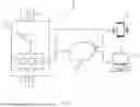
FIG. 1 is a high-level schematic diagram of a system according to one embodiment of the present disclosure; and
FIG. 2 is an example of a pump performance curve including a real time operating point for the pump.
Corresponding reference characters indicate corresponding parts throughout the several views. Although the drawings represent embodiments of the present disclosure, the drawings are not necessarily to scale, and certain features may be exaggerated or omitted in some of the drawings in order to better illustrate and explain the present disclosure.
DETAILED DESCRIPTION
Referring now to FIG. 1, a high-level schematic diagram of a system 10 according to one embodiment of the present disclosure is shown. The system 10 includes a pump 12, which receives a supply of liquid (e.g., water) at an inlet 13 from a supply pipe 14 and delivers the liquid from an outlet 15 to a discharge pipe 16. In some applications, the pump 12 delivers the liquid to various water consuming appliances (e.g., dishwashers, washing machines, etc.) and/or water delivery fixtures (e.g., sprinkling systems, faucets, spigots, shower heads, etc.). In other applications (e.g., dewatering applications), the pump 12 discharges the liquid to a desired discharge area such as a liquid collection area or a liquid drain area. As will be understood by those skilled in the art, many of the components of the pump 12 are omitted as not necessary for the description of the present disclosure. The pump 12 includes, among other things, a controller 18 that includes a processor 20, a memory device 22 and a communication device 24. The pump 12 may also include a flow sensor 26 which is in flow communication with the discharge pipe 16 of the pump 12 and provides flow measurements to the controller 18.
The communication device 24 is configured to communicate via a network 28, such as the Internet, with a smartphone 30 and/or a computing device 32 such as a laptop computer (collectively referred to herein as a “remote device”). The communication device 24 may also be configured to communicate with the smartphone 30 using a short-range wireless communication standard such as Bluetooth. The controller 18 functions as an Internet-of-Things (“IoT”) device and, via the communication device 24, may provide information to and/or receive commands from the smartphone 30 and/or the computing device 32. According to one embodiment of the present disclosure, as the pump 12 operates the communication device 24 provides operating data to an application operating on the smartphone 30 and/or to a website accessible by the smartphone 30 and/or the computing device 32. In the example described below, the communication device 24 provides real time data regarding the operating point of the pump 12. This information may be displayed on the display 31 of the smartphone 30 and/or the display 33 of the computing device 32.
Referring now to FIG. 2, an example of a type of pump operating curve interface 100 for display on a display 31 of the smartphone 30 and/or a display 33 of the computing device 32 is shown. The y-axis of the pump operating curve interface 100 is the total dynamic head (“TDH”) of the pump 12 in units of feet. The TDH is the amount of head or pressure on the suction side (i.e., at supply pipe 14) of the pump 12 (sometimes called static lift) plus the total of (1) the height that the water is to be pumped plus (2) the friction loss caused by the internal roughness or corrosion of the pipe(s) through which the water is pumped (i.e., the discharge pipe 16). In other words, TDH =Static Height +Static Lift +Friction Loss, where Static Height is the maximum height reached by the discharge pipe(s) 16 on the discharge side of the pump 12, Static Lift is the height the water will rise before arriving at the suction side of the pump 12 (i.e., at the supply pipe 14), and Friction Loss is the total losses due to friction in the pipes 14, 16 at a given flow rate. The x-axis of the pump operating curve interface 100 is the capacity of the pump 12. Capacity is the volumetric flow rate available at the suction side of the pump 12 in gallons per minute (“gpm”).
The pump operating curve interface 100 includes a plurality of performance curves. The performance curve 102 represents an example of TDH vs. capacity for a pump operating at 3600 RPM. The performance curve 104 represents an example of TDH vs. capacity for a pump operating at 2676 RPM. The performance curve 106 represents an example of TDH vs. capacity for a pump operating at 900 RPM. The pump operating curve interface 100 also displays a plurality of efficiency curves 108-122 that provide an indication of the efficiency of operation of the pump 12 at various combinations of TDH and capacity and across a range of pump operating speeds. For example, the efficiency curve 108 shows where the pump 12 achieves 54% efficiency across the range of speeds from 900 RPM to 3600 RPM. As shown, the efficiency of the pump 12 increases from efficiency curve 108 with increases in capacity or flow until the efficiency curves 116, 118, after which the efficiency decreases. The point 124 indicates the maximum efficiency point of operation for the pump 12 (i.e., 82% efficiency) operating at 3600 RPM.
The point 126 is the real time operating point of the pump 12 in terms of TDH and capacity. The real time operating point 126 is updated in substantially real time from information provided by the communication device 24 of the controller 18 of the pump 12 via the network 28 and/or direct wireless communication to the smartphone 30 and/or the computing device 32. The line 128 on the pump operating curve interface 100 shows that the current TDH for the pump 12 is 250 feet and the line 130 shows that the pump 12 is currently operating at a capacity of just under 300 gpm. A low efficiency zone 132 is shown on the pump operating curve interface 100 and represents an operating region in which the pump 12 is operating at low efficiency, which may result in damage to the pump 12 and/or higher cost operation. A transition zone 134 is also shown and corresponds to an operating region in which the pump 12 is operating at an acceptable, but still undesirable efficiency level. A high efficiency zone 136 on the pump operating curve interface 100 represents an operating region in which the pump 12 is operating at high efficiency, which may increase the expected operating life of the pump 12, result in lower cost operation, and/or reduce warranty claims. The low efficiency zone 132, the transition zone 134, and the high efficiency zone 136 are established according to known rules of thumb for the particular pump 12.
In certain embodiments, the pump operating curve also includes a message area 138 which provides information to the user about the current real time operating point 126 of the pump 12. In this example, as the pump 12 is currently operating in the transition zone 134, the message area 138 includes a message indicating operation of the pump 12 in the transition zone 134, which does not present an immediate risk of damage to the pump 12, but performance of the pump 12 may be improved (i.e., to the high efficiency zone 136) if adjustments to the operating parameters are made. For example, the user may change the output orifice size of the discharge pipe 16 using a valve to reduce capacity and/or increase TDH. In some cases, there may be a blockage at the supply pipe 14 which the user may remove. In certain embodiments, changes to the operating parameters of the pump 12 may be made by the user using the smartphone 30 and/or the computing device 32 in communication with the communication device 24 over the network 28. For example, the speed of operation of the pump 12 may be reduced.
A button 140 on the pump operating curve interface 100 allows the user to select the basis for the flow parameter of the real time operating point 126 of the pump 12. In the position shown, the flow parameter is measured using the flow sensor 26 in flow communication with the discharge pipe 16 of the pump 12. If the button 140 is deselected, flow is calculated or extrapolated (i.e., estimated) by the controller 18 from other operating parameters such as the speed of operation of the pump 12 and the pressure of the liquid at the discharge pipe 16, which may be determined by the processor 20.
Some embodiments may be described using the expression “coupled” and “connected” along with their derivatives. For example, some embodiments may be described using the term “coupled” to indicate that two or more elements are in direct physical or electrical contact. The term “coupled,” however, may also mean that two or more elements are not in direct contact with each other, but yet still co-operate or interact with each other. The embodiments are not limited in this context.
As used herein, the terms “comprises,” “comprising,” “includes,” “including,” “has,” “having” or any other variation thereof, are intended to cover a non-exclusive inclusion. For example, a process, method, article, or apparatus that comprises a list of elements is not necessarily limited to only those elements but may include other elements not expressly listed or inherent to such process, method, article, or apparatus.
As used herein, the modifier “about” used in connection with a quantity is inclusive of the stated value and has the meaning dictated by the context (for example, it includes at least the degree of error associated with the measurement of the particular quantity). When used in the context of a range, the modifier “about” should also be considered as disclosing the range defined by the absolute values of the two endpoints. For example, the range “from about 2 to about 4” also discloses the range “from 2 to 4.”
It should be understood that the connecting lines shown in the various figures contained herein are intended to represent exemplary functional relationships and/or physical couplings between the various elements. It should be noted that many alternative or additional functional relationships or physical connections may be present in a practical system. However, the benefits, advantages, solutions to problems, and any elements that may cause any benefit, advantage, or solution to occur or become more pronounced are not to be construed as critical, required, or essential features or elements. The scope is accordingly to be limited by nothing other than the appended claims, in which reference to an element in the singular is not intended to mean “one and only one” unless explicitly so stated, but rather “one or more.” Moreover, where a phrase similar to “at least one of A, B, or C” is used in the claims, it is intended that the phrase be interpreted to mean that A alone may be present in an embodiment, B alone may be present in an embodiment, C alone may be present in an embodiment, or that any combination of the elements A, B or C may be present in a single embodiment; for example, A and B, A and C, B and C, or A and B and C.
In the detailed description herein, references to “one embodiment,” “an embodiment,” “an example embodiment,” etc., indicate that the embodiment described may include a particular feature, structure, or characteristic, but every embodiment may not necessarily include the particular feature, structure, or characteristic. Moreover, such phrases are not necessarily referring to the same embodiment. Further, when a particular feature, structure, or characteristic is described in connection with an embodiment, it is submitted that it is within the knowledge of one skilled in the art with the benefit of the present disclosure to affect such feature, structure, or characteristic in connection with other embodiments whether or not explicitly described. After reading the description, it will be apparent to one skilled in the relevant art(s) how to implement the disclosure in alternative embodiments.
Furthermore, no element, component, or method step in the present disclosure is intended to be dedicated to the public regardless of whether the element, component, or method step is explicitly recited in the claims. No claim element herein is to be construed under the provisions of 35 U.S.C. 112(f), unless the element is expressly recited using the phrase “means for.” As used herein, the terms “comprises,” “comprising,” or any other variation thereof, are intended to cover a non-exclusive inclusion, such that a process, method, article, or apparatus that comprises a list of elements does not include only those elements but may include other elements not expressly listed or inherent to such process, method, article, or apparatus.
Various modifications and additions can be made to the exemplary embodiments discussed without departing from the scope of the present disclosure. For example, while the embodiments described above refer to particular features, the scope of this disclosure also includes embodiments having different combinations of features and embodiments that do not include all of the described features. Accordingly, the scope of the present disclosure is intended to embrace all such alternatives, modifications, and variations as fall within the scope of the claims, together with all equivalents thereof.
Claims
What is claimed is:1. A system for providing a real-time operating curve of a pump coupled to a supply pipe and a discharge pipe, comprising:
a controller in operative communication with the pump, the controller including a processor and a communication device; and
a remote device communicatively coupled to the communication device, the remote device including a display;
wherein the controller is configured to provide to the remote device, via the communication device, real time data representing an operating point of the pump, the real time data including a total dynamic head parameter and a capacity parameter;
wherein the remote device is configured to display on the display of the remote device, a pump operating curve interface including a plurality of efficiency zones and an indication of the operating point of the pump in one of the plurality of efficiency zones; and
wherein when the operating point of the pump is in a first efficiency zone of the plurality of efficiency zones, the pump operating curve interface further includes a message area including at least one recommendation for adjusting at least one operating parameter of the pump to change the operating point of the pump to correspond to a second efficiency zone of the plurality of efficiency zones.
2. The system of claim 1, wherein the pump operating curve interface further includes a plurality of performance curves representing total dynamic head parameters and capacity parameters for a corresponding plurality of operating speeds of the pump.
3. The system of claim 1, wherein the pump operating curve interface further includes a plurality of efficiency curves representing an efficiency of operation of the pump at a corresponding plurality of operating speeds of the pump.
4. The system of claim 1, wherein the plurality of efficiency zones includes a low efficiency zone, a transition zone and a high efficiency zone.
5. The system of claim 4, wherein the first efficiency zone is one of the low efficiency zone or the transition zone.
6. The system of claim 1, wherein the remote device is a smartphone.
7. The system of claim 1, wherein the remote device is communicatively coupled to the communication device via a network.
8. The system of claim 7, wherein the network is a short range wireless communication network.
9. The system of claim 1, wherein the capacity parameter is a volumetric flow rate determined by the processor from flow measurements provided by a flow sensor in flow communication with the discharge pipe.
10. The system of claim 1, wherein the at least one recommendation includes one of a recommendation to change an output orifice size of the discharge pipe or a recommendation to remove a blockage in the supply pipe.
11. The system of claim 1, wherein the remote device is configured to permit a user to adjust the at least one operating parameter of the pump via a network.
12. The system of claim 1, wherein the pump operating curve interface further includes a button which permits a user to toggle between displaying the indication of the real time operating point of the pump based on flow measurements from a flow sensor in flow communication with the discharge pipe and displaying the indication of the real time operating point of the pump based on an estimate of flow calculated by the processor using a speed of operation of the pump and pressure measurements from a pressure sensor in flow communication with the discharge pipe.
13. A pump configured to facilitate display of a real-time operating curve of the pump, comprising:
at least one inlet configured to couple to at least one supply pipe for supplying liquid to the pump;
at least one outlet configured to couple to at least one discharge pipe for discharging liquid from the pump;
at least one processor configured to determine a current total dynamic head parameter of the pump and a current capacity of the pump; and
a communication device in communication with the at least one processor, the communication device being configured to provide the current total dynamic head parameter and the current capacity parameter to a remote device;
wherein the remote device is configured to display a pump operating curve interface including a plurality of efficiency zones and an indication of a current operating point of the pump in one of the plurality of efficiency zones, the current operating point being based upon the current total dynamic head parameter and the current capacity parameter; and
wherein when the current operating point of the pump is in a first efficiency zone of the plurality of efficiency zones, the communication device provides to the remote device at least one recommendation for adjusting at least one operating parameter of the pump to change the current operating point of the pump to correspond to a second efficiency zone of the plurality of efficiency zones.
14. The pump of claim 13, wherein the pump operating curve interface further includes a plurality of performance curves representing total dynamic head parameters of the pump and capacity parameters of the pump for a corresponding plurality of operating speeds of the pump.
15. The pump of claim 13, wherein the pump operating curve interface further includes a plurality of efficiency curves representing an efficiency of operation of the pump at a corresponding plurality of operating speeds of the pump.
16. The pump of claim 13, wherein the plurality of efficiency zones includes a low efficiency zone, a transition zone and a high efficiency zone.
17. The pump of claim 16, wherein the first efficiency zone is one of the low efficiency zone or the transition zone.
18. The pump of claim 13, further comprising a flow sensor in flow communication with the discharge pipe, wherein the current capacity parameter is a volumetric flow rate determined by the processor from flow measurements provided by the flow sensor.
19. The pump of claim 13, wherein the at least one recommendation includes one of a recommendation to change an output orifice size of the discharge pipe or a recommendation to remove a blockage in the supply pipe.
20. The pump of claim 13, wherein the communication device is configured to permit a user to adjust the at least one operating parameter of the pump via a network.
21. A method for providing a real-time operating curve of a pump coupled to a supply pipe and a discharge pipe, comprising:
determining, by a processor, real time data representing an operating point of the pump, the real time data including a total dynamic head parameter and a capacity parameter; and
communicating the real time data, by the processor, to a communication device of the pump;
communicating the real time data, by the communication device, to a remote device;
causing, by the processor, the remote device to display a pump operating curve interface including a plurality of efficiency zones and an indication of the operating point of the pump in one of the plurality of efficiency zones; and
communicating, by the communication device, to the remote device at least one recommendation for adjusting at least one operating parameter of the pump to change the operating point of the pump to correspond to a second efficiency zone of the plurality of efficiency zones.
Images & Drawings included:


Sources:
- United States Patent and Trademark Office - verify current appl. status at the USPTO↗
Recent applications in this class:
- » 20260098532 2026-04-09
CONTROL UNIT FOR CONTROLLING ELECTRIC OIL PUMPS - » 20260085677 2026-03-26
SYSTEMS AND METHODS FOR CAPTURING EMISSIONS WITH AN INTERNAL COMBUSTION ENGINE - » 20260078749 2026-03-19
SYSTEM AND METHOD FOR HIERARCHICAL COMPRESSOR CONTROL - » 20260009382 2026-01-08
SYSTEM AND METHOD FOR SLEEP MODE FOR A PUMPING SYSTEM - » 20250376979 2025-12-11
MOTOR POWER OPTIMIZATION FOR DOWNHOLE MOTORS - » 20250369436 2025-12-04
METHOD FOR DETERMINING OPERATIONAL INFORMATION OF A METERING PUMP - » 20250320860 2025-10-16
Controlling Fracturing Pumps in a Hydraulic Fracturing System - » 20250305495 2025-10-02
CONTROL CALIBRATION APPARATUS FOR VARIABLE-CAPACITY PUMP AND METHOD THEREOF - » 20250270992 2025-08-28
MEMBRANE PUMP USAGE CONDITION DETECTION - » 20250230809 2025-07-17
PUMP PERFORMANCE DATA LOGGING APPARATUS