REFRIGERANT CAPTURE ENCLOSURE FOR HVAC SYSTEMS
US20260146751A1
2026-05-28
18/959,091
2024-11-25
Smart Summary: A refrigerant capture enclosure is designed to collect any refrigerant that leaks from HVAC systems. It includes a branch selector box that has valves and pipes to control the refrigerant flow. If there is a leak from this box, the refrigerant will be directed into a special chamber within the enclosure. This setup helps prevent harmful refrigerants from escaping into the environment. Other related systems and methods are also mentioned to enhance its effectiveness. 🚀 TL;DR
Abstract:
A refrigerant capture enclosure for receiving refrigerant leaked from an HVAC component is provided. In one embodiment, an HVAC apparatus includes a branch selector box and a refrigerant capture enclosure. The branch selector box includes valves and piping that are installed in a branch selector box housing. Further, the branch selector box housing is installed in a chamber of the refrigerant capture enclosure such that, in the event that refrigerant leaks from the branch selector box housing, the refrigerant leaked from the branch selector box housing is received in the chamber of the refrigerant capture enclosure. Additional systems, devices, and methods are also disclosed.
Inventors:
- Hideyuki Nakagawa 7 🇺🇸 Houston, TX, United States
- Brandin Whiting 1 🇺🇸 Cypress, TX, United States
- Takashi Goto 1 🇺🇸 Katy, TX, United States
Applicant:
Interested in similar patents?
Get notified when new applications in this technology area are published.
Classification:
F24F11/36 » CPC main
Control or safety arrangements for purposes related to the operation of the system, e.g. for safety or monitoring; Responding to malfunctions or emergencies to leakage of heat-exchange fluid
Description
BACKGROUND
This section is intended to introduce the reader to various aspects of art that may be related to various aspects of the presently described embodiments. This discussion is believed to be helpful in providing the reader with background information to facilitate a better understanding of the various aspects of the present embodiments. Accordingly, it should be understood that these statements are to be read in this light, and not as admissions of prior art.
Modern residential, commercial, and industrial customers expect indoor spaces to be climate controlled. Heating, ventilation, and air conditioning (“HVAC”) systems often circulate an indoor space's air over low-temperature (for cooling) or high-temperature (for heating) sources, thereby adjusting the indoor space's ambient air temperature. HVAC systems generate these low-and high-temperature sources by, among other techniques, taking advantage of a well-known physical principle—a fluid transitioning from gas to liquid releases heat, while a fluid transitioning from liquid to gas absorbs heat. Within a typical HVAC system, a fluid refrigerant circulates through a closed loop of tubing that uses a compressor and other flow-control devices to manipulate the refrigerant's flow and pressure, causing the refrigerant to cycle between the liquid and gas phases. Generally, these phase transitions occur within the HVAC's heat exchangers, which are part of the closed loop and designed to transfer heat between the circulating refrigerant and flowing ambient air.
In some instances, an HVAC system is a split system having indoor and outdoor units, each having a heat exchanger, connected in fluid communication. As would be expected in such cases, the heat exchanger providing heating or cooling to the climate-controlled space or structure is described adjectivally as being “indoors,” and the heat exchanger transferring heat with the surrounding outdoor environment is described as being “outdoors.” The refrigerant circulating between the indoor and outdoor heat exchangers—transitioning between phases along the way—absorbs heat from one location and releases it to the other. Those in the HVAC industry describe this cycle of absorbing and releasing heat as “pumping.” To cool the climate-controlled indoor space, heat is “pumped” from the indoor side to the outdoor side. And the indoor space is heated by doing the opposite, pumping heat from the outdoors to the indoors.
SUMMARY
Certain aspects of some embodiments disclosed herein are set forth below. It should be understood that these aspects are presented merely to provide the reader with a brief summary of certain forms the invention might take and that these aspects are not intended to limit the scope of the invention. Indeed, the invention may encompass a variety of aspects that may not be set forth below.
Some embodiments of the present disclosure generally relate to HVAC systems that circulate refrigerant to transfer heat and condition air. More specifically, some embodiments relate to a refrigerant capture enclosure constructed to receive refrigerant-containing equipment, such as a branch selector box. In the event of refrigerant leaking from the received equipment, the refrigerant capture enclosure may contain the leaked refrigerant and inhibit its spread to surrounding space outside the enclosure. A refrigerant gas sensor may be used to detect leaked refrigerant within the enclosure and to trigger mitigation, which may include stopping flow of refrigerant through the equipment. In some cases, the mitigation also or instead includes activating ventilation equipment to remove leaked refrigerant.
Various refinements of the features noted above may exist in relation to various aspects of the present embodiments. Further features may also be incorporated in these various aspects as well. These refinements and additional features may exist individually or in any combination. For instance, various features discussed below in relation to one or more of the illustrated embodiments may be incorporated into any of the above-described aspects of the present disclosure alone or in any combination. Again, the brief summary presented above is intended only to familiarize the reader with certain aspects and contexts of some embodiments without limitation to the claimed subject matter.
BRIEF DESCRIPTION OF THE DRAWINGS
These and other features, aspects, and advantages of certain embodiments will become better understood when the following detailed description is read with reference to the accompanying drawings in which like characters represent like parts throughout the drawings, wherein:
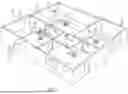
FIG. 1 illustrates schematically an HVAC system for conditioning indoor spaces within a structure in accordance with one embodiment of the present disclosure;
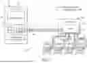
FIG. 2 is a schematic process-and-instrumentation drawing of an HVAC system for conditioning indoor spaces within a structure, the HVAC system including an outdoor unit, indoor units, and a flow control assembly with a branch selector box disposed in a refrigerant capture enclosure, in accordance with one embodiment;
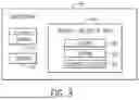
FIG. 3 generally depicts components of a branch selector box and refrigerant capture enclosure in accordance with one embodiment;
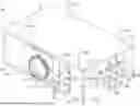
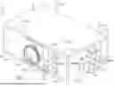
FIG. 4 is a front perspective view of a refrigerant flow control assembly having a branch selector box positioned in a refrigerant capture enclosure in accordance with one embodiment;
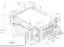
FIG. 5 is a front perspective view of the refrigerant flow control assembly of FIG. 4 with the refrigerant capture enclosure drawn in phantom to show additional details of the branch selector box in accordance with one embodiment;
FIG. 6 is a rear perspective view of the refrigerant flow control assembly of FIGS. 4 and 5 in accordance with one embodiment;
FIG. 7 is a rear perspective view of the refrigerant flow control assembly of FIGS. 4-6 with the refrigerant capture enclosure drawn in phantom to show additional details of the branch selector box in accordance with one embodiment;
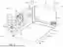
FIG. 8 is an exploded view of the refrigerant capture enclosure of FIGS. 4-7 in accordance with one embodiment;
FIG. 9 is an exploded view of a refrigerant capture enclosure similar to that of FIG. 8 in accordance with one embodiment;
FIG. 10 is a top plan view of the refrigerant capture enclosure of FIGS. 4-7, with a top panel removed to show an interior chamber of the enclosure, in accordance with one embodiment;
FIG. 11 is a detail view of a portion of the refrigerant capture enclosure of FIG. 4 in accordance with one embodiment; and
FIGS. 12 and 13 generally depict ventilation systems with fans for ventilating leaked refrigerant from refrigerant capture enclosures in accordance with some embodiments.
DETAILED DESCRIPTION OF SPECIFIC EMBODIMENTS
Specific embodiments of the present disclosure are described below. In an effort to provide a concise description of these embodiments, all features of an actual implementation may not be described. It should be appreciated that in the development of any such actual implementation, as in any engineering or design project, numerous implementation-specific decisions must be made to achieve the developers'specific goals, such as compliance with system-related and business-related constraints, which may vary from one implementation to another. Moreover, it should be appreciated that such a development effort might be complex and time-consuming, but would nevertheless be a routine undertaking of design, fabrication, and manufacture for those of ordinary skill having the benefit of this disclosure.
When introducing elements of various embodiments, the articles “a,” “an,” “the,” and “said” are intended to mean that there are one or more of the elements. The terms “comprising,” “including,” and “having” are intended to be inclusive and mean that there may be additional elements other than the listed elements. Moreover, any use of “top,” “bottom,” “front,” “back,” “side,” “above,” “below,” other directional terms, and variations of these terms is made for convenience, but does not require any particular orientation of the components.
By way of example, and turning now the figures, FIG. 1 illustrates a split HVAC system 10 in accordance with one embodiment. As depicted, the system 10 provides heating and cooling for a commercial structure 12. But the concepts disclosed herein are applicable to a myriad of heating and cooling situations, including industrial and residential settings. And while some HVAC systems provide each of heating, ventilation, and air conditioning, others do not. The term “HVAC system,” as used herein, means a system that provides one or more of heating, ventilation, air conditioning, or refrigeration. For example, an air conditioner that does not provide heating or ventilation is considered an HVAC system. The use of the term “HVAC” in describing a system, unit, component, equipment, etc., herein is not to be interpreted as a requirement that each of heating, ventilation, and air conditioning is provided.
Many North American residences, as well as some commercial and industrial buildings, employ “ducted” systems, in which a structure's ambient air is circulated over a central indoor heat exchanger and then routed back through relatively large ducts (or ductwork) to multiple climate-controlled indoor spaces. However, the use of a central heat exchanger can limit the ducted system's ability to vary the temperature of the multiple indoor spaces to meet different occupants'needs. This is often resolved by increasing the number of separate systems within the structure—with each system having its own outdoor unit that takes up space on the structure's property, which may not be available or may be available only at a premium.
Some buildings also or instead employ “ductless” systems, in which refrigerant is circulated between an outdoor unit and one or more indoor units to heat and cool specific indoor spaces. Unlike ducted systems, ductless systems route conditioned air to the indoor space directly from the indoor unit—without ductwork.
The described HVAC system 10 of FIG. 1 includes a split system with an outdoor unit 16, which mainly comprises components for transferring heat with the environment outside the structure 12, and indoor units 18, which mainly comprise components for transferring heat with the air inside the structure 12. In the illustrated structure, the indoor units 18 are ductless indoor units that provide heating and cooling to various indoor spaces 14. In other embodiments, however, the HVAC system 10 could also or instead include a ducted indoor unit. Fluid refrigerant circulates between the outdoor unit 16 and the indoor units 18 through a network 20 of refrigerant lines generally depicted in FIG. 1.
The HVAC system 10 is also depicted in FIG. 1 as including a refrigerant flow control assembly 24 for routing refrigerant among the outdoor unit 16 and the indoor units 18 through the network 20 of refrigerant lines. As discussed in greater detail below, the refrigerant flow control assembly 24 can include a branch selector box. And while a single outdoor unit 16, a single flow control assembly 24, and four indoor units 18 are depicted in FIG. 1, the numbers of each of these components may vary, in any desirable combination, in other embodiments. The HVAC system 10, for example, may include multiple outdoor units 16, may include multiple flow control assemblies 24, and may include any suitable number of indoor units 18 for conditioning air within the structure 12.
The HVAC system 10 of FIG. 1 includes thermostats 22. Each thermostat 22 can sense an indoor space's temperature and allows the structure occupants to “set” the desired temperature for that sensed indoor space 14. The thermostat may operate using a simple on/off protocol that sends 24V signals, for example, to the HVAC system (e.g., to an indoor unit 18) to either activate or deactivate various components; or it may be a more complex thermostat that uses a “communicating protocol,” such as ClimateTalk or a proprietary protocol, that sends and receives data signals and can provide more complex operating instructions to the HVAC system 10.
As shown in FIG. 2, the outdoor unit 16 includes a compressor 36 and a heat exchanger 38 installed in a housing 34, such as a metal or plastic casing. The compressor 36 compresses fluid refrigerant and motivates circulation of the refrigerant to other units, such as the flow control assembly 24 and the indoor units 18. A fan 40 promotes airflow across the heat exchanger 38 to facilitate heat transfer between the outdoor air and the heat exchanger 38. The outdoor unit 16 may be an up-flow unit, with the fan 40 generating airflow discharged from the outdoor unit 16 in an upward direction (e.g., perpendicular to the ground), or a side-flow unit in which the fan 40 is arranged to discharge air from a side of the outdoor unit 16 (e.g., parallel to the ground). In some embodiments, the outdoor unit 16 includes multiple compressors 36, heat exchangers 38, and fans 40. The outdoor unit 16 can also include flow-control devices 42 (e.g., four-way valves) to direct refrigerant flow between components of the HVAC system 10, and electrical control circuity 48 (e.g., a control board) for controlling operation of various components, such as the compressor 36 and the flow-control devices 42.
As also shown in FIG. 2, the flow control assembly 24 of the HVAC system 10 includes a branch selector box 46 for routing refrigerant among the outdoor unit 16 and the indoor units 18. In this depicted example, the HVAC system 10 is a “three-pipe” variable refrigerant flow system, in which the network 20 of refrigerant lines includes three refrigerant lines 44 that connect the outdoor unit 16 to the branch selector box 46. These three refrigerant lines 44 can include a liquid line that carries predominantly liquid refrigerant (e.g., high-pressure liquid refrigerant for cooling), a discharge line that carries predominately gas refrigerant (e.g., high-pressure hot gas for heating), and a gas line that carries predominately gas refrigerant (e.g., low-pressure gas returning to the outdoor unit). In other instances, the HVAC system 10 could be provided as a “two-pipe” system with just a liquid line and a gas line.
The branch selector box 46 directs liquid refrigerant or gas refrigerant to indoor units 18 connected via additional refrigerant lines 52 for cooling or heating. For instance, in FIG. 2 the branch selector box 46 is a multi-port branch selector that controls flow of refrigerant to multiple indoor units 18, which each include a heat exchanger 54 and a fan 56. The fan 56 generates airflow that draws ambient air from an indoor space 14 into the indoor unit 18, passes that air across the heat exchanger 54, and discharges the air into the indoor space 14. The multiple indoor units 18 may also include additional components, such as an expansion valve (or other refrigerant metering device) and electrical control circuity (e.g., a control board).
For cooling an indoor space 14 with an indoor unit 18, liquid refrigerant may flow from the branch selector box 46 to the heat exchanger 54 of the indoor unit 18 to absorb heat from airflow generated by the fan 56 across the heat exchanger 54. For heating, hot gas refrigerant may flow from the branch selector box 46 to a heat exchanger 54 of an indoor unit 18 to add heat to airflow generated by the fan 56 across the heat exchanger 54. In some instances, the indoor units 18 may be operated in different modes simultaneously. That is, one or more of the indoor units 18 may be operated in a cooling mode while at least one of the other indoor units 18 is operated in a heating mode.
Branch selector boxes and other refrigerant-containing flow path equipment are often installed in confined, unoccupied areas that lack monitoring, ventilation, or air circulation. Branch selector boxes may be installed in a ceiling void space (e.g., above a suspended ceiling) in a structure, for instance. In some embodiments, however, the flow control assembly 24 of the HVAC system 10 includes a refrigerant capture enclosure 60. As generally depicted in FIG. 2, the branch selector box 46 can be positioned inside the refrigerant capture enclosure 60. In the event of a refrigerant leak from the branch selector box 46, the leaked refrigerant may be contained in the refrigerant capture enclosure 60 to reduce or avoid leaking of the refrigerant into the surrounding environment outside the enclosure 60. And while described herein as being used with a branch selector box 46, a refrigerant capture enclosure 60 may be used to surround other refrigerant-containing equipment (e.g., other refrigerant-containing flow path equipment of an HVAC system) in other applications.
Certain components of the branch selector box 46 and the refrigerant capture enclosure 60 are generally depicted in FIG. 3 in accordance with one embodiment. In this example, the branch selector box 46 includes a housing containing valves 62 (e.g., electronic expansion valves) and piping 64 for routing refrigerant between the outdoor unit 16 and the indoor units 18. A control board 66 can receive command signals from other components (e.g., thermostats 22 or indoor units 18) and, in response, selectively control operation of the valves 62 to regulate refrigerant flow through the piping 64 and connected refrigerant lines.
The branch selector box 46 can be received in the refrigerant capture enclosure 60, which can include a control board 70 and a sensor 72. In at least some embodiments, the sensor 72 is a refrigerant gas sensor for detecting refrigerant within the refrigerant capture enclosure 60. The refrigerant gas sensor 72 can be a semiconductor sensor, an infrared or other optical sensor, or some other sensor type suitable to detect the refrigerant used in the HVAC system 10, such as an A2L refrigerant (e.g., R-32 or HFO-1234yf), another mildly flammable refrigerant, or an A1 refrigerant (e.g., R-410a or R-22). The refrigerant gas sensor 72 can be positioned at any suitable location within the enclosure 60. For instance, the refrigerant gas sensor 72 can be positioned outside the branch selector box 46 but within the refrigerant capture enclosure 60 to detect refrigerant that has leaked out of the branch selector box 46 and is contained within the refrigerant capture enclosure 60. Although a refrigerant gas sensor could be installed in the branch selector box 46, in at least some embodiments there is not any refrigerant gas sensor in the branch selector box 46 and the refrigerant gas sensor 72 is positioned somewhere inside the refrigerant capture enclosure 60 but outside of the branch selector box 46.
The control board 70 is configured (e.g., programmed) to prevent circulation of refrigerant through piping 64 of the branch selector box 46 in response to detection, with the refrigerant gas sensor 72, of refrigerant leaked from the branch selector box 46 housing. More specifically, in some cases the control board 70 is configured to send a signal to the control board 66 of the branch selector box 46, in response to detection of refrigerant with the refrigerant gas sensor 72, to cause the control board 66 to act to prevent circulation of refrigerant in piping 64. This may include, for example, the control board 66 commanding valves 62 in the branch selector box 46 to be closed or sending a control signal to the outdoor unit 16 to cause the outdoor unit 16 to not route refrigerant to the branch selector box 46, such as by turning off the compressor 36. Detecting refrigerant or a refrigerant leak can include detecting any amount of refrigerant or detecting some amount (e.g., concentration) of refrigerant that is above a set minimum threshold. That is, the control board 70 may be configured to send a signal to the control board 66 to take action to stop refrigerant circulation if any refrigerant is detected with the refrigerant gas sensor 72 or may be configured to send such a signal if sufficient refrigerant (e.g., above a minimum threshold) is detected by the refrigerant gas sensor 72.
As discussed in further detail below, a ventilation system may be used to vent refrigerant from inside the refrigerant capture enclosure 60. In such cases, the control board 70 may also or instead be configured to activate the ventilation system when refrigerant is detected with the refrigerant gas sensor 72. The control board 70, for example, may send a command signal to a ventilation fan to activate the fan and cause the detected refrigerant to flow out of the enclosure 60.
The control board 70 may be provided as a single control board 70 or as multiple control boards 70. In some embodiments, for example, a single control board is configured to prevent refrigerant circulation and to activate a ventilation system after detecting a refrigerant leak with sensor 72. In other embodiments, these functions may be divided across multiple control boards (e.g., one board for preventing refrigerant circulation and another board for ventilation). Likewise, while a sensor 72 is described above, the refrigerant capture enclosure 60 could be instrumented with multiple sensors 72 in some cases. Multiple sensors 72 could include a single refrigerant gas sensor with one or more other types of sensors or multiple refrigerant gas sensors with or without one or more other types of sensors.
The control boards described herein (e.g., control boards 66 and 70) can have any suitable form and are provided as printed circuit boards in at least some embodiments. The control boards can include a processor (e.g., a microprocessor or microcontroller) and a memory (e.g., an electrically erasable programmable read-only memory) that stores instructions executed by the processor to provide various functions, such as detecting refrigerant leaks, preventing refrigerant circulation, and activating a ventilation system. The control boards 66 and 70 can communicate with each other and to other components via wired connections or in any other suitable manner.
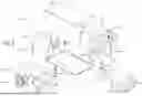
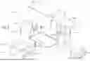
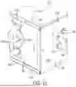
The flow control assembly 24 may be provided in any suitable form but is depicted as an assembly 80 in FIGS. 4-7 in accordance with one embodiment. More specifically, FIGS. 4 and 6 are front and rear perspective views of the full assembly 80 having the refrigerant capture enclosure 60 with the branch selector box 46 installed inside the enclosure 60. FIGS. 5 and 7 are also front and rear perspective views of the assembly 80 but with the refrigerant capture enclosure 60 casing drawn in phantom to better illustrate features of the branch selector box 46. Further, FIG. 8 is an exploded view of the refrigerant capture enclosure 60.
In this depicted example, the refrigerant capture enclosure 60 is formed with three pairs of opposing panels assembled as a casing in the shape of a rectangular prism. The panels include a front panel 82 and rear panel 84, a side panel 86 and another side panel 88, and a bottom panel 90 and top panel 92. These panels can be formed of sheet metal (e.g., galvanized steel) or any other suitable material. The panels may be assembled with fasteners 94 (FIG. 8), such as self-tapping fasteners. Removable panels (e.g., rear panel 84 and top panel 92) facilitate service access to the branch selector box 46.
The branch selector box 46 includes a housing 110 with fastened panels, some of which may also be removeable panels to facilitate access to internal components of the branch selector box 46. In some embodiments, the housing 110 is a two-part housing, with a first housing part 112 having the valves 62 and the piping 64, and a second housing part 114 having the control board 66. The first and second housing parts 112 and 114 may be separate casings attached to one another in any suitable manner. Hanging rods 116 may be included in some instances to facilitate installation of the branch selector box 46 in a desired space.
Connecting pipes 96 and 98 of the branch selector box 46 extend outwardly from the housing 110 and extend outside the refrigerant capture enclosure 60. The connecting pipes 96 facilitate connection with refrigerant lines (e.g., refrigerant lines 44) for communicating refrigerant between the branch selector box 46 and the outdoor unit 16. In at least some embodiments, including that depicted in FIGS. 4-7, connecting pipes 96 extend from opposite sides of the branch selector box 46 to facilitate connection of multiple branch selector boxes 46 in series (a pass-through configuration). But the connecting pipes 96 on one of the sides could be sealed (e.g., capped) or omitted in other instances, such as if the HVAC system 10 has just a single branch selector box 46 connected to the outdoor unit 16 or multiple branch selector boxes 46 connected to the outdoor unit 16 in parallel. Connecting pipes 98 facilitate connection with refrigerant lines 52 (e.g., piping) for communicating refrigerant between the branch selector box 46 and the indoor units 18. In this depicted embodiment, branch selector box 46 is a four-port branch selector, with four pairs of connecting pipes 98 for connection to four indoor units 18. In other instances, the branch selector box 46 could be a multi-port branch selector with a different number of ports, or a single-port branch selector. In such cases, the branch selector box 46 can have a pair of connecting pipes 98 per port. When installed in an HVAC system 10, the connecting pipes 96 and 98 can be connected to refrigerant lines via brazing or in any other acceptable fashion.
The refrigerant capture enclosure 60 can be configured in any suitable manner to permit the connecting pipes 96 and 98 extending outwardly from the branch selector box housing 110 to pass out of the refrigerant capture enclosure 60. In at least some embodiments, this includes allowing the connecting pipes 96 and 98 to pass through apertures of the refrigerant capture enclosure 60. Additionally, in the depicted example of FIGS. 4-8, the refrigerant capture enclosure 60 includes removable plates 102 and 104 having such apertures. Pipe grommets 106 installed at the apertures seal against the connecting pipes 96 and 98 to prevent egress of refrigerant that is contained in the refrigerant capture enclosure 60 from leaking out of the enclosure 60 along the outside of the connecting pipes 96 and 98 through the apertures. The pipe grommets 106 can be made with an elastomer or any other suitable sealing material. Further, the apertures and pipe grommets 106 may be provided with various dimensions, such as to facilitate passage of, and sealing with, connecting pipes 96 and 98 of different outer diameters. The pipe grommets 106 may be installed and removed from the plates 102 and 104. By way of example, the plate 104 is shown without pipe grommets 106 in the apertures (denoted with reference numeral 108) in FIG. 8. Each of the plates 102 and 104 may be attached to a panel of the refrigerant capture enclosure 60 with fasteners 94 or in any other suitable manner.
In at least some embodiments, the plates 102 or 104 are adapter plates selected from groups of interchangeable plates having differing designs, which may include other plates 102 and 104 having greater or fewer apertures or having apertures in different positional arrangements to accommodate different connection configurations of the branch selector box 46. This increases design flexibility, such as by allowing panels of the refrigerant capture enclosure to be used in a variety of HVAC applications. In FIG. 9, for example, the refrigerant capture enclosure 60 is depicted as having plates 102 having two apertures, rather than three, for use in a “two-pipe” HVAC system 10. In an embodiment in which the assembly 80 has connecting pipes 96 on only one side, the plate 102 on the opposite side could be provided as a blind plate. The plate 104 is also shown in FIG. 9 as having four apertures 108 configured for use with a two-port branch selector box 46. In some cases, if a plate 102 or 104 has more apertures than needed to allow passage of connecting pipes 96 or 98 through the plate, any extra apertures may be sealed, such as with a plug, rather than using a different plate.
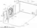
As noted above, the refrigerant capture enclosure 60 is configured to receive refrigerant that may leak out of the branch selector box 46. In some embodiments, the refrigerant capture enclosure 60 is also configured to facilitate ventilation of leaked refrigerant out of the enclosure 60. For instance, the refrigerant capture enclosure 60 depicted in FIG. 8 includes a ventilation connection assembly 122 that attaches to the side panel 86. The ventilation connection assembly 122 has an opening or port 124. A ventilation duct may be connected to the ventilation connection assembly 122 (e.g., via the depicted neck surrounding the port 124) to allow leaked refrigerant to flow out of the refrigerant capture enclosure 60 through the port 124 and the connected ventilation duct. If ventilation is not provided for enclosures 60, removeable ventilation covers could be used to seal ports 124 of the ventilation connection assemblies 122.
The refrigerant capture enclosure 60 of some embodiments also includes a damper that may be selectively opened to facilitate air flow through the enclosure 60 and aid ventilation. In FIG. 8, for example, the refrigerant capture enclosure 60 includes a damper assembly 130 that attaches to the side panel 88. The damper assembly 130 can have various configurations but is shown in FIGS. 6 and 8 as having a rotary plate 132 that may be opened and closed with an actuator 134 (e.g., a motor). During normal operation, the rotary plate 132 may be held in a closed position that inhibits flow through the damper assembly 130. If a refrigerant leak is detected within the refrigerant capture enclosure 60, the rotary plate 132 may be moved via the actuator 134 (e.g., based on a command signal from the control board 70) to an open position to promote air flow through the enclosure 60. Either or both of the ventilation connection assembly 122 and the damper assembly 130 could be omitted in other embodiments. The damper assembly 130 could be replaced with an additional ventilation connection assembly 122, for example, or both the damper assembly 130 and the ventilation connection assembly 122 could be replaced with blind plates 128 (FIG. 9), such as if the refrigerant capture enclosure 60 will not be installed with an enclosure ventilation unit in an HVAC system 10. Having the ventilation connection assembly 122, the damper assembly 130, and a blind plate 128 as modular components of the refrigerant capture enclosure 60 may enhance installation flexibility. In other embodiments, however, any of these components could be provided as an integral part of a panel (e.g., side panel 86 or 88).
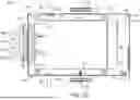
In addition to the components forming a housing for isolating leaked refrigerant from a surrounding environment, the refrigerant capture enclosure 60 can include other components. Examples of a refrigerant gas sensor 72 and a control board 70, attached to a mounting plate 138, inside the housing of the enclosure 60 are depicted in FIGS. 8-10, for instance. But other components could also or instead be included.
As shown in FIG. 10, the panels of the refrigerant capture enclosure 60 generally define an interior chamber 140 that receives the branch selector box 46. The refrigerant gas sensor 72 and the control board 70 may also be positioned within the chamber 140. The connecting pipes 96 and 98 of the branch selector box 46 extend outwardly from the housing 110 and beyond the panels 82, 86, and 88 of the enclosure 60. Pipe insulation 142 is provided about portions of the connecting pipes 96 and 98. Insulation may also be provided within the housing 110 of the branch selector box 46, such as about the valves 62 and the piping 64. Any suitable material may be used for the pipe insulation 142 and the insulation within the housing 110, examples of which include urethane foam, polyurethane foam, or polyethylene foam. In some cases, the insulation material may be impermeable to refrigerant gas, and leaked refrigerant (e.g., from the valves 62 or piping 64) may exit the housing 110 by passing between a connecting pipe 96 or 98 and the pipe insulation 142 surrounding that connecting pipe. In at least some embodiments, the pipe insulation 142 extends along only portions of the connecting pipes 96 and 98 (leaving other portions exposed) to provide air gaps 144 within the refrigerant capture enclosure 60, allowing any leaked refrigerant traveling along the connecting pipes 96 and 98 to escape from the pipe insulation 142 within the chamber 140. In FIG. 10, these air gaps 144 are generally depicted between the pipe grommets 106 and distal ends of the pipe insulation 142.
Sealing material may be placed along seams of the refrigerant capture enclosure 60 to prevent or inhibit flow of leaked refrigerant out of the enclosure 60 at the seams. As an example, seals 148 are shown along seams between panels 82, 86, 90, and 92 of the refrigerant capture enclosure 60 depicted in FIG. 11. It will be appreciated that seals 148 may be provided along seams throughout the enclosure 60, such as along seams between any of the panels, along plates 102 and 104, or at any other location of the enclosure 60 through which a leaked refrigerant could inadvertently escape. The seals 148 may include tape, foam, caulk, elastomer, mastic, or some other material, which may be applied to interior surfaces, exterior surfaces, or between adjacent surfaces of the enclosure 60.
As discussed above, a ventilation duct may be connected to the refrigerant capture enclosure 60 to facilitate venting of leaked refrigerant out of the enclosure 60. In FIG. 12, a ventilation system 150 is shown with three refrigerant capture enclosures 60 connected in parallel to a ventilation fan 152 (e.g., a blower) by one or more ducts 154. In FIG. 13, a similar ventilation system 160 instead shows the refrigerant capture enclosures 60 connected in series to the ventilation fan 152 by ducts 154. The control boards 70 of the refrigerant capture enclosures 60 may be connected to communicate with the ventilation fan 152, as generally represented by the dashed lines in FIGS. 12 and 13. In either case, the control boards 70 of the enclosures 60 may each be connected for direct communication to the ventilation fan 152, as in FIG. 12, or may be daisy-chained for communication to the ventilation fan 152 and with the control boards 70 of other enclosures 60, as in FIG. 13. In response to detecting refrigerant within a refrigerant capture enclosure 60, the control board 70 of that refrigerant capture enclosure 60 may send a signal to cause the ventilation fan 152 to activate and draw the detected refrigerant away from the enclosure 60. As noted above, in some embodiments the control board 70 may also send a command signal to the damper assembly 130 to open the damper (e.g., rotary plate 132) and promote air flow through the refrigerant capture enclosure 60. When the refrigerant capture enclosures 60 are connected in series, such as in FIG. 13, the control board 70 of the enclosure 60 in which refrigerant is detected can communicate a signal to the other enclosures 60 to cause the control boards 70 of those other enclosures 60 to also open the dampers of those other enclosures 60. In another embodiment with refrigerant capture enclosures 60 connected in series to a ventilation fan 152, only the distal enclosure 60 furthest in sequence from the ventilation fan 152 has a damper assembly 130 that is opened in response to a detected refrigerant leak in any of the enclosures 60. The other enclosures 60 may each have ventilation connection assemblies 122 on opposite sides to facilitate connection to the ducts 154. Additionally, in certain embodiments, a ventilation fan 152 may also or instead be used to ventilate surrounding space outside a refrigerant capture enclosure 60 in response to detecting refrigerant within the enclosure 60.
While the aspects of the present disclosure may be susceptible to various modifications and alternative forms, specific embodiments have been shown by way of example in the drawings and have been described in detail herein. But it should be understood that the invention is not intended to be limited to the particular forms disclosed. Rather, the invention is to cover all modifications, equivalents, and alternatives falling within the spirit and scope of the invention as defined by the following appended claims.
Claims
1. An HVAC apparatus comprising:
a branch selector box including valves and piping that are installed in a branch selector box housing; and
a refrigerant capture enclosure, wherein the branch selector box housing is installed in a chamber of the refrigerant capture enclosure such that, in the event that refrigerant leaks from the branch selector box housing, the refrigerant leaked from the branch selector box housing is received in the chamber of the refrigerant capture enclosure.
2. The HVAC apparatus of claim 1, comprising a refrigerant gas sensor positioned outside of the branch selector box and within the refrigerant capture enclosure.
3. The HVAC apparatus of claim 2, comprising at least one control board for the refrigerant capture enclosure.
4. The HVAC apparatus of claim 3, wherein the at least one control board for the refrigerant capture enclosure includes a control board configured to prevent circulation of refrigerant through the piping of the branch selector box in response to detection of the refrigerant leaked from the branch selector box housing by the refrigerant gas sensor outside the branch selector box.
5. The HVAC apparatus of claim 4, wherein the control board configured to prevent circulation of refrigerant through the piping of the branch selector box in response to detection of the refrigerant leaked from the branch selector box housing by the refrigerant gas sensor outside the branch selector box is configured to prevent circulation of refrigerant through the piping of the branch selector box by sending a signal to a branch selector box control board to cause the branch selector box control board to prevent the circulation of refrigerant.
6. The HVAC apparatus of claim 3, wherein the at least one control board for the refrigerant capture enclosure is installed within the chamber of the refrigerant capture enclosure.
7. The HVAC apparatus of claim 1, wherein the refrigerant capture enclosure is configured to permit connection pipes extending outwardly from the branch selector box housing to extend outside of the refrigerant capture enclosure.
8. The HVAC apparatus of claim 7, wherein the refrigerant capture enclosure includes pipe grommets to seal against the connection pipes and prevent egress of refrigerant out of the refrigerant capture enclosure at locations at which the connection pipes extend outwardly from the refrigerant capture enclosure.
9. The HVAC apparatus of claim 7, wherein the refrigerant capture enclosure includes a plate having apertures for receiving two or more of the connection pipes.
10. The HVAC apparatus of claim 9, wherein the plate is attached to a panel of the refrigerant capture enclosure.
11. The HVAC apparatus of claim 1, wherein the refrigerant capture enclosure includes panels secured together with fasteners.
12. The HVAC apparatus of claim 11, wherein the refrigerant capture enclosure includes a sealing material positioned along seams to inhibit leakage of refrigerant from the chamber of the refrigerant capture enclosure.
13. An HVAC apparatus comprising:
an indoor unit having a heat exchanger;
a branch selector box connected to the indoor unit with piping and configured to direct refrigerant to the heat exchanger of the indoor unit via the piping;
a refrigerant capture enclosure surrounding the branch selector box, wherein the refrigerant capture enclosure includes a casing defining an interior chamber in which the branch selector box is received, and the refrigerant capture enclosure is instrumented with a refrigerant gas sensor outside the branch selector box to detect refrigerant that has leaked out of the branch selector box.
14. The HVAC apparatus of claim 13, comprising a ventilation fan connected in fluid communication with the interior chamber of the refrigerant capture enclosure.
15. The HVAC apparatus of claim 14, comprising a control board configured to control activation of the ventilation fan, in response to detecting refrigerant in the interior chamber of the refrigerant capture enclosure with the refrigerant gas sensor, to cause the refrigerant to flow out of the interior chamber.
16. The HVAC apparatus of claim 15, wherein the refrigerant capture enclosure includes a damper that can be opened to promote air flow through the interior chamber.
17. The HVAC apparatus of claim 13, wherein the branch selector box is a multi-port branch selector box.
18. A method of operating an HVAC system, the method comprising:
operating an HVAC system having an outdoor unit and an indoor unit to condition air within a structure, wherein the HVAC system includes a branch selector box to direct refrigerant to the indoor unit, and the branch selector box has valves and piping that are installed in a branch selector box housing;
detecting refrigerant within a refrigerant capture enclosure outside of the branch selector box; and
preventing operation of the HVAC system to condition air within the structure in response to detecting refrigerant within the refrigerant capture enclosure outside of the branch selector box.
19. The method of claim 18, comprising activating a fan to ventilate the detected refrigerant from the refrigerant capture enclosure.
20. The method of claim 19, wherein activating the fan to ventilate the detected refrigerant from the refrigerant capture enclosure includes activating the fan to draw refrigerant from the refrigerant capture enclosure through ductwork connecting the refrigerant capture enclosure to the fan.
Images & Drawings included:

Sources:
- United States Patent and Trademark Office - verify current appl. status at the USPTO↗
Recent applications in this class:
- » 20260146752 2026-05-28
HVAC REFRIGERANT DETECTION AND MITIGATION SYSTEM - » 20260126196 2026-05-07
SYSTEM AND METHOD FOR PROVIDING COOLING DURING REFRIGERANT LEAK - » 20260092715 2026-04-02
SYSTEMS AND METHODS FOR REFRIGERANT LEAKAGE DETECTION - » 20260049731 2026-02-19
HVAC SYSTEM AND METHODS OF USING THE SAME FOR LEAK DETECTION - » 20260043568 2026-02-12
AIR-CONDITIONER CONTROL SYSTEM, INFORMATION PROCESSING APPARATUS AND AIR-CONDITIONER CONTROL METHOD - » 20260016176 2026-01-15
REFRIGERANT LEAK DETECTION SYSTEM AND METHOD - » 20260002685 2026-01-01
Refrigerant Sensor Integration into Climate Control Systems - » 20250389437 2025-12-25
System and Method for Detecting a Refrigerant Leak in an HVAC System Using a Subcooling Temperature - » 20250383106 2025-12-18
HVAC System with Leak Detection and Method of Use - » 20250383105 2025-12-18
REFRIGERANT LEAK DETECTION SYSTEM