HVAC REFRIGERANT DETECTION AND MITIGATION SYSTEM
US20260146752A1
2026-05-28
18/959,444
2024-11-25
Smart Summary: An HVAC system has been designed to detect and manage refrigerant leaks. It includes a furnace with a control board and a blower, along with a refrigerant circuit that has a heat exchanger coil. This coil helps transfer heat using refrigerant that flows through it. A sensor is placed outside the refrigerant circuit to monitor for leaks, and a control board processes commands from the thermostat. If a leak is detected, the control board can adjust the system's operations to prevent further issues. 🚀 TL;DR
Abstract:
An HVAC refrigerant detection and mitigation control system is provided. In one embodiment, and HVAC system includes a furnace and a refrigerant circuit. The furnace includes a main control board and a blower, while the refrigerant circuit includes a heat exchanger coil installed within a housing. The heat exchanger coil is operable to exchange heat with air in the housing via a refrigerant passing through the heat exchanger coil. The HVAC system also includes a refrigerant sensor positioned outside the refrigerant circuit and a refrigerant detection and mitigation control board. The refrigerant detection and mitigation control board is configured to receive HVAC commands issued by a thermostat and to selectively relay the received HVAC commands to the main control board based on whether the refrigerant from the refrigerant circuit is detected via the refrigerant sensor. Additional systems, devices, and methods are also disclosed.
Inventors:
- Douglas Notaro 30 🇺🇸 Cypress, TX, United States
- Tathagata De 1 🇺🇸 Katy, TX, United States
Applicant:
Interested in similar patents?
Get notified when new applications in this technology area are published.
Classification:
F24F11/36 » CPC main
Control or safety arrangements for purposes related to the operation of the system, e.g. for safety or monitoring; Responding to malfunctions or emergencies to leakage of heat-exchange fluid
Description
BACKGROUND
This section is intended to introduce the reader to various aspects of art that may be related to various aspects of the presently described embodiments. This discussion is believed to be helpful in providing the reader with background information to facilitate a better understanding of the various aspects of the present embodiments. Accordingly, it should be understood that these statements are to be read in this light, and not as admissions of prior art.
Modern residential and industrial customers expect indoor spaces to be climate controlled. In general, heating, ventilation, and air conditioning (“HVAC”) systems circulate an indoor space's air over low-temperature (for cooling) or high-temperature (for heating) sources, thereby adjusting the indoor space's ambient air temperature. HVAC systems generate these low-and high-temperature sources by, among other techniques, taking advantage of a well-known physical principle: a fluid transitioning from gas to liquid releases heat, while a fluid transitioning from liquid to gas absorbs heat. Within a typical HVAC system, a fluid refrigerant circulates through a closed loop of tubing that uses a compressor and other flow-control devices to manipulate the refrigerant's flow and pressure, causing the refrigerant to cycle between the liquid and gas phases. Generally, these phase transitions occur within the HVAC's heat exchangers, which are part of the closed loop and designed to transfer heat between the circulating refrigerant and flowing ambient air.
In some instances, an HVAC system is a split system having indoor and outdoor units, each having a heat exchanger, connected in fluid communication. As would be expected in such cases, the heat exchanger providing heating or cooling to the climate-controlled space or structure is described adjectivally as being “indoors,” and the heat exchanger transferring heat with the surrounding outdoor environment is described as being “outdoors.” The refrigerant circulating between the indoor and outdoor heat exchangers—transitioning between phases along the way—absorbs heat from one location and releases it to the other. Those in the HVAC industry describe this cycle of absorbing and releasing heat as “pumping.” To cool the climate-controlled indoor space, heat is “pumped” from the indoor side to the outdoor side. The indoor space can be heated by doing the opposite, pumping heat from the outdoors to the indoors. In some instances, a furnace may also or instead be used to heat the indoor space.
SUMMARY
Certain aspects of some embodiments disclosed herein are set forth below. It should be understood that these aspects are presented merely to provide the reader with a brief summary of certain forms the invention might take and that these aspects are not intended to limit the scope of the invention. Indeed, the invention may encompass a variety of aspects that may not be set forth below.
Some embodiments of the present disclosure generally relate to refrigerant detection and mitigation in HVAC systems. More specifically, some embodiments relate to HVAC systems with a refrigerant detection and mitigation controller in a furnace. In one embodiment, a refrigerant detection and mitigation control board is interposed between a main control board, such as a furnace control board, and a thermostat. The refrigerant detection and mitigation control board can relay operating commands from the thermostat to the main control board. If a refrigerant leak is detected in the HVAC system, the refrigerant detection and mitigation control board sends an override command to the main control board. The override command may cause the main control board to direct operation of a blower to facilitate dispersal of the detected refrigerant. In at least some instances, the refrigerant detection and mitigation control board also prevents energization of a compressor to avoid circulation of refrigerant within a refrigerant circuit of the HVAC system when leaked refrigerant is detected. Further still, in some embodiments, a blower is configured to run automatically when communication with the main controller is lost. In an HVAC system with a refrigerant leak, this blower configuration may facilitate dispersal of leaked refrigerant even if the blower is unable to establish communication with the main controller of the system.
Various refinements of the features noted above may exist in relation to various aspects of the present embodiments. Further features may also be incorporated in these various aspects as well. These refinements and additional features may exist individually or in any combination. For instance, various features discussed below in relation to one or more of the illustrated embodiments may be incorporated into any of the above-described aspects of the present disclosure alone or in any combination. Again, the brief summary presented above is intended only to familiarize the reader with certain aspects and contexts of some embodiments without limitation to the claimed subject matter.
BRIEF DESCRIPTION OF THE DRAWINGS
These and other features, aspects, and advantages of certain embodiments will become better understood when the following detailed description is read with reference to the accompanying drawings in which like characters represent like parts throughout the drawings, wherein:
FIG. 1 illustrates schematically an HVAC system for heating and cooling indoor spaces within a structure in accordance with one embodiment of the present disclosure;
FIG. 2 is a schematic process-and-instrumentation drawing of an HVAC system for heating and cooling indoor spaces within a structure in accordance with one embodiment;
FIG. 3 depicts a split HVAC system with a refrigerant detection and mitigation controller connected between a main controller and a thermostat in accordance with one embodiment;
FIG. 4 is a block diagram showing the main controller and the refrigerant detection and mitigation controller of FIG. 3, as well as a motor controller of a blower of FIG. 3, as control boards in accordance with one embodiment;
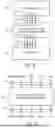
FIG. 5 generally depicts the refrigerant detection and mitigation controller of FIG. 3 connected between the main controller and the thermostat with wires in accordance with one embodiment;
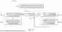
FIG. 6 is a functional diagram depicting signals communicated to and from the refrigerant detection and mitigation board in accordance with one embodiment;
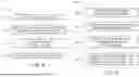
FIG. 7 is a flowchart representing a method of operating an HVAC system having a refrigerant detection and mitigation controller in accordance with one embodiment;
FIG. 8 is a flowchart representing a method for mitigating effects of a refrigerant leak in an HVAC system in accordance with one embodiment; and
FIG. 9 is a flowchart representing a method of operating a blower of an HVAC system in accordance with one embodiment.
DETAILED DESCRIPTION OF SPECIFIC EMBODIMENTS
Specific embodiments of the present disclosure are described below. In an effort to provide a concise description of these embodiments, all features of an actual implementation may not be described. It should be appreciated that in the development of any such actual implementation, as in any engineering or design project, numerous implementation-specific decisions must be made to achieve the developers'specific goals, such as compliance with system-related and business-related constraints, which may vary from one implementation to another. Moreover, it should be appreciated that such a development effort might be complex and time-consuming, but would nevertheless be a routine undertaking of design, fabrication, and manufacture for those of ordinary skill having the benefit of this disclosure.
When introducing elements of various embodiments, the articles “a,” “an,” “the,” and “said” are intended to mean that there are one or more of the elements. The terms “comprising,” “including,” and “having” are intended to be inclusive and mean that there may be additional elements other than the listed elements.
By way of example, and turning now to the figures, FIG. 1 illustrates a split HVAC system 10 in accordance with one embodiment. As depicted, the system 10 provides heating and cooling for a residential structure 12. But the concepts disclosed herein are applicable to a myriad of heating and cooling situations, including industrial and commercial settings. And while some HVAC systems provide each of heating, ventilation, and air conditioning, others do not. The term “HVAC system,” as used herein, means a system that provides one or more of heating, ventilation, air conditioning, or refrigeration. For example, an air conditioner that does not provide heating or ventilation is considered an HVAC system. The use of the term “HVAC” in describing a system, unit, component, equipment, etc., herein is not to be interpreted as a requirement that each of heating, ventilation, and air conditioning is provided.
Many North American residences, as well as some commercial and industrial buildings, employ “ducted” systems, in which a structure's ambient air is circulated over a central indoor heat exchanger and then routed back through relatively large ducts (or ductwork) to multiple climate-controlled indoor spaces. However, the use of a central heat exchanger can limit the ducted system's ability to vary the temperature of the multiple indoor spaces to meet different occupants'needs. This is often resolved by increasing the number of separate systems within the structure—with each system having its own outdoor unit that takes up space on the structure's property, which may not be available or at a premium.
Some buildings also or instead employ “ductless” systems, in which refrigerant is circulated between an outdoor unit and one or more indoor units to heat and cool specific indoor spaces. Unlike ducted systems, ductless systems route conditioned air to the indoor space directly from the indoor unit—without ductwork.
The described HVAC system 10 of FIG. 1 is a split system with two primary portions: the outdoor unit 14, which mainly comprises components for transferring heat with the environment outside the structure 12; and the indoor units 16 & 18, which mainly comprise components for transferring heat with the air inside the structure 12. In the illustrated structure, a ducted indoor unit 16 and ductless indoor units 18 provide heating and cooling to various indoor spaces 20.
Focusing on the ducted indoor unit 16, it is depicted as having an air-handler unit (or AHU) 24 that provides airflow circulation, which in the illustrated embodiment draws ambient indoor air via a return vent 26, passes that air over one or more heating/cooling elements (i.e., sources of heating or cooling), and then routes that conditioned air, whether heated or cooled, back to the various climate-controlled spaces 20 through supply vents 28. As depicted in FIG. 1, air between the AHU 24 and the vents 26 and 28 is carried by ducts or ductwork 30, which are relatively large pipes that may be rigid or flexible. A blower 32 provides the motivational force to generate airflow and circulate the ambient air through the vents 26 and 28, AHU 24, and ducts 30.
As shown, the ducted indoor unit 16 is a “dual-fuel” system that has multiple heating elements. A gas furnace 34, which may be located downstream (in terms of airflow) of the blower 32, combusts natural gas to produce heat in furnace tubes (not shown) that coil through the furnace. These furnace tubes act as a heating element for the ambient indoor air being pushed out of the blower 32, over the furnace tubes, and into supply ducts 30 to supply vents 28. During conventional heating and cooling operations in a dual-fuel system, air from the blower 32 may be routed over an indoor heat exchanger 36 (to exchange heat) and into the supply ducts 30; the furnace 34 is generally operated when robust heating is desired. In some instances, the furnace 34 may be an electric furnace, with one or more heat strips or other electric heating elements for heating air passing through the AHU 24, rather than a gas furnace.
The blower 32, furnace 34, and indoor heat exchanger 36 may be packaged as an integrated AHU, or those components may be modular. Moreover, it is envisaged that the positions of the furnace, indoor heat exchanger, and blower can be reversed or rearranged. Internal components of the blower 32, the furnace 34, and the indoor heat exchanger 36 can be positioned within one or more casings, cabinets, or other housings (integrated or modular). Further, while the indoor unit 16 is depicted in FIGS. 1 and 2 as a dual-fuel system and is described below in reference to these figures as using the heat exchanger 36 for both heating and cooling the indoor spaces 20, the indoor unit 16 may take any other suitable form. In some embodiments, for instance, the indoor unit 16 includes a gas furnace appliance having a blower and a heating element in a shared cabinet to provide heating, and the indoor heat exchanger 36 of the indoor unit 16 is used for cooling but not for heating.
The indoor heat exchanger 36—which in this embodiment for the ducted indoor unit 16 is an A-coil 38 (FIG. 2), as it known in the industry—can act as a heating or cooling element that adds or removes heat from the structure by manipulating the pressure and flow of refrigerant circulating within and between the A-coil 38 and the outdoor unit 14 via refrigerant lines 40.
In the illustrated embodiment of FIG. 1, the state of the A-coil 38 (i.e., absorbing or releasing heat) is the opposite of the outdoor heat exchanger 42. More specifically, if heating is desired, the illustrated indoor heat exchanger 36 acts as a condenser, aiding transition of the refrigerant from a high-pressure gas to a high-pressure liquid and releasing heat in the process. And the outdoor heat exchanger 42 acts as an evaporator, aiding transition of the refrigerant from a low-pressure liquid to a low-pressure gas, thereby absorbing heat from the outdoor environment. If cooling is desired, the outdoor unit 14 has flow-control devices 44 that reverse the flow of the refrigerant—such that the outdoor heat exchanger 42 acts as a condenser and the indoor heat exchanger 36 acts as an evaporator. The outdoor unit 14 also contains other equipment—like a compressor 46, which provides the motivation for circulating the refrigerant, and electrical control circuitry 48, which provides command and control signals to various components of the system 10.
The outdoor unit 14 is a side-flow unit that houses, within a plastic or metal casing or housing 50, the various components that manage the refrigerant's flow and pressure. This outdoor unit 14 is described as a side-flow unit because the airflow across the outdoor heat exchanger 42 is motivated by a fan that rotates about an axis that is non-perpendicular with respect to the ground. In contrast, “up-flow” devices generate airflow by rotating a fan about an axis generally perpendicular to the ground. (As illustrated, the Y-axis is perpendicular to the ground.) In one embodiment, the side-flow outdoor unit 14 may have a fan 52 that rotates about an axis that is generally parallel to the ground. (As illustrated, the X-and Z-axes are parallel to the ground.) It is envisaged that either up-flow or side-flow units could be employed. Advantageously, the side-flow outdoor unit 14 provides a smaller footprint than traditional up-flow units, which are more cubic in nature.
In addition to the ducted indoor unit 16, the illustrated HVAC system has ductless indoor units 18 that also circulate refrigerant, via the refrigerant lines 40, between the outdoor heat exchanger 42 and the ductless indoor units'heat exchangers. The ductless indoor units 18 may work in conjunction with or independent of the ducted indoor unit 16 to heat or cool the given indoor spaces 20. That is, a given indoor space 20 may be heated or cooled with the structure's air that has been conditioned by the ductless indoor unit 18 and by the air routed through the ductwork 30 after being conditioned by the A-coil 38, or it may be entirely conditioned by the ductless indoor unit or the ducted indoor unit working independent of one another. As another embodiment, the A-coil refrigerant loop may be operated to provide cooling or heating only—and the ductless indoor units may also be designed to provide cooling or heating only.
As is well known, the HVAC system may be in communication with a thermostat 54 that senses the indoor space's temperature and allows the structure occupants to “set” the desired temperature for that sensed indoor space. The thermostat may operate using a simple on/off protocol that sends 24V signals, for example, to the HVAC system to either activate or deactivate various components; or it may be a more complex thermostat that uses a “communicating protocol,” such as ClimateTalk or a proprietary protocol, that sends and receives data signals and can provide more complex operating instructions to the HVAC system.
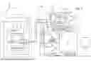
FIG. 2 provides further detail about the various components of an HVAC system and their operation. The compressor 46 draws in gaseous refrigerant and pressurizes it, sending it into the closed refrigerant loop 40 via compressor outlet 60. A flow meter 62 may be used to measure the flow of refrigerant out of the compressor. The outlet 60 is connected to a reversing valve 64, which may be electronic, hydraulic, or pneumatic and which controls the routing of the high-pressure gas to the indoor or outdoor heat exchangers. Moreover, the outlet 60 may be coupled to an oil separator 66 that isolates oil expelled by the compressor and, via a return line 68, returns the separated oil to the compressor inlet 70—to help prevent that expelled oil from reaching the downstream components and helping ensure the compressor maintains sufficient lubrication for operation. The oil return line 68 may include a valve 72 that reduces the pressure of the oil returning to the compressor 46.
To cool the structure, the high-pressure gas is routed to the outdoor heat exchangers 42, where airflow generated by the fans 52 aids the transfer of heat from the refrigerant to the environment—causing the refrigerant to condense into a liquid that is at high-pressure. As shown, the outdoor unit 14 has multiple heat exchangers 42 and fans 52 connected in parallel, to aid the HVAC system's operation.
The refrigerant leaving the heat exchangers 42 is or is almost entirely in the liquid state and flows through or bypasses a metering device 74. From there, the high-pressure liquid refrigerant flows into a series of receiver check valves 76 that manage the flow of refrigerant into the receiver 78. The receiver 78 stores refrigerant for use by the system and provides a location where residual high-pressure gaseous refrigerant can transition into liquid form. The receiver may be located within the casing 50 of the outdoor unit or may be external to the casing 50 of the outdoor unit (or the system may have no receiver at all). From the receiver 78, the high-pressure liquid refrigerant flows to the indoor units 16, 18, specifically to metering devices 80 that restrict the flow of refrigerant into each heat exchanger of the indoor units 16, 18, to reduce the refrigerant's pressure. The refrigerant leaves the indoor metering devices 80 as a low-pressure liquid (or mostly liquid). The metering device 80 may take any suitable form. The metering device 80 may be an electronic expansion valve, for instance, but other types of metering devices—like capillaries, thermal expansion valves, pistons, reduced orifice tubing, or a fixed orifice expansion device—are also envisaged.
Low-pressure liquid refrigerant is then routed to the indoor heat exchangers 36. As illustrated, the indoor heat exchanger 36 for the ducted indoor unit 16 is an “A-coil” style heat exchanger 38. But the heat exchanger 38 can be an “N-coil” (or “Z-coil”) style heat exchanger or a slab coil or can take any other suitable form. Airflow generated by the blower 32 aids in the absorption of heat from the flowing air by the refrigerant, causing the refrigerant to transition from a low-pressure liquid to a low-pressure gas as it progresses through the indoor heat exchanger 36. And the airflow generated by the blower 32 drives the now cooled air into the ductwork 30 (specifically the supply ducts), cooling the indoor spaces 20. In a similar fashion, the low-pressure liquid refrigerant is routed to the indoor heat exchangers 36 of the ductless indoor units 18, where it is evaporated, causing the refrigerant to absorb heat from the environment. However, unlike the ducted indoor unit, the ductless indoor units circulate air without ductwork, using a local fan 52, for example.
The refrigerant leaving the indoor heat exchangers 36, which is now entirely or mostly a low-pressure gas, is routed to the reversing valve 64 that directs refrigerant to the accumulator 82. Any remaining liquid in the refrigerant is separated in the accumulator, ensuring that the refrigerant reaching the compressor inlet 70 is almost entirely in a gaseous state. The compressor 46 then repeats the cycle, by compressing the refrigerant and expelling it as a high-pressure gas.
For heating the structure 12, the process is reversed. High-pressure gas is still expelled from the compressor outlet 60 and through the oil separator 66 and flow meter 62. However, for heating, the reversing valve 64 directs the high-pressure gas to the indoor heat exchangers 36. There, the refrigerant—aided by airflow from the blower 32 or the fans 52—transitions from a high-pressure gas to a high-pressure liquid, rejecting heat. And that heat is driven by the airflow from the blower 32 into the ductwork 30 or by the fans 52 in the ductless indoor units 18, heating the indoor spaces 20. If more robust heating is desired, the gas furnace 34 may be ignited, either supplementing or replacing the heat from the heat exchanger. That generated heat is driven into the indoor spaces by the airflow produced by the blower 32. In other instances, electric heating elements (e.g., of an electric furnace 34 of the indoor units 16 or 18) may also or instead be used to provide heat to the indoor spaces 20.
The high-pressure liquid refrigerant leaving each indoor heat exchanger 36 is routed through or past the given metering device 80. Using the refrigerant lines 40, the high-pressure liquid refrigerant is routed to the receiver check valves 76 and into the receiver 78. As described above, the receiver 78 stores liquid refrigerant and allows any refrigerant that may remain in gaseous form to condense. From the receiver, the high-pressure liquid refrigerant is routed to an outdoor metering device 74, which lowers the pressure of the liquid. Like the indoor metering device 80, the illustrated outdoor metering device 74 may take any suitable form. It is envisaged that the outdoor metering device 74 could be any number of devices, including capillaries, electronic expansion valves, thermal expansion valves, pistons, reduced orifice tubing, or fixed orifice expansion devices, for example.
The lower-pressure liquid refrigerant is then routed to the outdoor heat exchangers 42, which are acting as evaporators. That is, the airflow generated by the fans 52 aids the transition of low-pressure liquid refrigerant to a low-pressure gaseous refrigerant, absorbing heat from the outdoor environment in the process. The low-pressure gaseous refrigerant exits the outdoor heat exchanger 42 and is routed to the reversing valve 64, which directs the refrigerant to the accumulator 82. The compressor 46 then draws in gaseous refrigerant from accumulator 82, compresses it, and then expels it via the outlet 60 as high-pressure gas, for the cycle to be repeated.
As illustrated in FIG. 2, the system is a “two-pipe” variable refrigerant flow system, in which the HVAC system's refrigerant is circulated between the outdoor and indoor units via two refrigerant lines 40, one of which is a line that carries predominantly liquid refrigerant (a liquid line 84) and one of which is a line that carries predominately gas refrigerant (a gas line 86). However, it is also envisaged that, in other embodiments, aspects described herein could be applied to a three-pipe variable refrigerant flow system, in which in addition to the gas and liquid lines a third discharge line aids in the circulation of refrigerant.
In many instances, the structure 12 may have had a previous HVAC system with pre-existing refrigerant piping at least partially built into the structure's interior walls. For example, the pre-existing system may be a traditional HVAC unit that uses circulating refrigerant for cooling only and a gas furnace for heating, with all of the conditioned air delivered to the interior spaces via the ductwork. And the pre-existing refrigerant lines—which are built into the walls of the structure—may have a gas line with a 6/8-inch, ⅞-inch, or 9/8-inch outer diameter gas line. However, in certain embodiments, the outdoor unit 14 may have more modern refrigerant piping, which tends to be smaller in outer diameter. For example, the outdoor unit 14 may be 2-, 3-, or 4-Ton unit that has a gas line diameter of ⅝ inch. It would be laborious and cost ineffective to replace the pre-existing gas line in the structure with ⅝-inch diameter tubing. Accordingly, the illustrated HVAC system includes a coupler 88 that helps couple the varying diameter gas lines to one another. For example, the coupler 88 may facilitate coupling of the outdoor unit's ⅝-inch diameter gas line to the structure's pre-existing 6/8-inch, ⅞-inch, or 9/8-inch diameter gas line. In another embodiment, the outdoor unit 14 may be a 5-Ton unit with a gas line having a diameter of 6/8 inch. The coupler could facilitate coupling of this outdoor unit with a pre-existing gas line of ⅞-inch or 9/8-inch diameter.
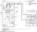
Although operation of the heat exchanger 36 for heating and cooling the indoor spaces 20 is described above, it is again noted that the HVAC system 10 may instead be configured to use the heat exchanger 36 and circulating refrigerant for just cooling and to instead use a furnace 34 (e.g., one or more heating elements in a gas furnace appliance) as the primary or sole heat source for heating the indoor spaces 20. Such a configuration is depicted in FIG. 3 in accordance with one embodiment. In this example, the indoor unit 16 includes a furnace appliance 100 (e.g., a gas furnace appliance) having a blower 32 and a heating element 108 (e.g., furnace tubes) in a shared cabinet 102. The depicted indoor unit 16 also includes a heat exchanger 36 with a heat exchanger coil 38 in a housing 104. As generally shown in FIG. 3, refrigerant can be circulated through a refrigerant circuit to move refrigerant within and between the coil 38, the heat exchanger 42, and the compressor 46. In at least some instances, the housing 104 is a separate component outside the cabinet 102. In others, however, the heat exchanger coil 38 may be installed inside the shared cabinet 102. In still other cases, the blower 32 and the heating element 108 could be provided in separate cabinets or housings.
As described above, the blower 32 can operate to move air past the heating element 108 and the heat exchanger coil 38 for conditioning (e.g., heating of the air with the heating element 108 or cooling of the air with the heat exchanger coil 38). The indoor unit 16 includes a main controller, which may be provided in the form of a main control board 110 (e.g., a gas furnace control board inside the cabinet 102 in FIG. 3) that controls operation of components of the furnace 100, such as the blower 32 and the heating element 108. For instance, the main control board 110 may issue component commands to control combustion in a fuel-based heating element 108 and to cause a blower motor 106 to drive the blower 32 to move air through the indoor unit 16. More specifically, the main control board 110 may receive HVAC operating commands (e.g., COOL, HEAT, and FAN commands or “calls”) and control operation of furnace components based on such operating commands. Upon receipt by the main control board 110 of a COOL, HEAT, or FAN call, the main control board 110 may command the blower motor 106 to drive the blower 32 to push air through the indoor unit. In at least some instances, the blower 32 is configured to be driven by the blower motor 106 at more than one speed, such as at a first speed for a FAN call and a second speed (e.g., a faster speed than the first speed) for a COOL call. The blower motor 106 may be provided in any suitable form, such as a two-speed motor configured to drive the blower 32 at either the first speed or the second speed, when activated, or a variable speed motor.
In addition to a main controller (e.g., the main control board 110), the indoor unit 16 may also include additional controllers. In FIG. 3, for example, the indoor unit 16 includes a refrigerant detection and mitigation controller, which is provided in at least some embodiments as a control board 112. The refrigerant detection and mitigation control board 112 may receive signals from one or more sensors 114 of the HVAC system 10. While various sensors may be used in the HVAC system 10, at least one of the one or more sensors 114 can be a refrigerant gas sensor to detect gaseous refrigerant outside of the refrigerant circuit that carries refrigerant to and from the heat exchanger coil 38 (e.g., refrigerant that has leaked from the coil 38 or another portion of the refrigerant circuit). In some instances, the sensors 114 may include two (or more) refrigerant gas sensors, such as a first refrigerant gas sensor 114 installed in the furnace cabinet 102 and a second refrigerant gas sensor 114 installed in the housing 104 of the heat exchanger 36. In others, just a single refrigerant gas sensor 114 may be used. A refrigerant gas sensor 114 may be installed in the furnace cabinet 102, the housing 104, or at any other suitable location. A refrigerant gas sensor 114 can be a semiconductor sensor, an infrared or other optical sensor, or some other sensor type suitable to detect the refrigerant used in the HVAC system 10. In some embodiments, such refrigerant includes an A2L refrigerant (e.g., R-32 or HFO-1234yf), another mildly flammable refrigerant, or an A1 refrigerant (e.g., R-410a or R-22). If multiple refrigerant gas sensors 114 are used in the HVAC system 10, such as for redundancy or increased sensitivity, the multiple refrigerant gas sensors 114 may be of the same type or of different types.
The refrigerant detection and mitigation control board 112 is connected in communication with the main control board 110 and a thermostat 54. More particularly, in the example depicted in FIG. 3 the refrigerant detection and mitigation control board 112 is interposed between the thermostat 54 and the main control board 110 so as to intercept HVAC commands from the thermostat 54 (e.g., COOL, HEAT, or FAN calls) to the main control board 110. As discussed in greater detail below, the refrigerant detection and mitigation control board 112 may relay such HVAC commands from the thermostat 54 to the main control board 110 or may instead provide an override command from the refrigerant detection and mitigation control board 112 to the main control board 110. Operation of the HVAC system 10 may then be controlled via the main control board 110 based on the command received by the main control board. In at least some embodiments, the refrigerant detection and mitigation control board 112 provides an override command, in place of one or more commands from the thermostat 54, to the main control board 110 in response to detecting a refrigerant leak with a refrigerant gas sensor 114. It will be appreciated that a command from the thermostat 54 may also be communicated to other equipment. In some cases, for instance, a COOL command from the thermostat 54 is communicated to the outdoor unit 14 to activate the compressor 46 and circulate refrigerant within the refrigerant circuit. This may include transmitting the COOL command to a contactor 116 that closes a power supply circuit to allow supply power to be provided to one or more components of the outdoor unit 14, such as the compressor 46 and a fan 52 (FIG. 1).
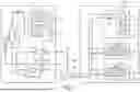
The main controller and the refrigerant detection and mitigation controller of the indoor unit 16 can take any suitable form but, as discussed above, are provided as control boards (e.g., printed circuit boards) in at least some embodiments. For example, as generally depicted in FIG. 4, the main controller may be provided as a main control board 110 and the refrigerant detection and mitigation controller may be provided as a refrigerant detection and mitigation control board 112. Each of the boards 110 and 112 is shown in FIG. 4 as having a processor 122 (e.g., a microprocessor or microcontroller), a memory 124, and input/output devices 126 (e.g., wire terminals and communications circuitry). In at least some embodiments, the memory 124 (e.g., an electrically erasable programmable read-only memory) of each board 110 and 112 stores instructions executed by the processor 122 of the board to facilitate monitoring or control of HVAC components. Additionally, the blower motor 106 may include a motor controller 128 (which may also be provided as a control board) having a processor 122, memory 124, and input/output devices 126. The motor controller 128 is configured (e.g., programmed) to control operation of the blower motor 106 to drive the blower 32 in response to command signals from the main control board 110. Further, as discussed in greater detail below, in at least some embodiments the motor controller 128 is programmed or otherwise configured to automatically drive the blower 32 in response to a loss of communication between a main controller (e.g., the main control board 110) and the blower motor 106.
The main control board 110 may control operation of some or all functions of the furnace 100. Examples of such control include controlling operation of the blower 32 (via blower motor 106 and its motor controller 128) and controlling operation of the heating element 108. In a gas furnace 100, controlling operation of the heating element 108 may include controlling supply of natural gas or another fuel, controlling ignition of the fuel, and controlling an inducer fan to create a draft through a combustion chamber of the heating element 108. If an electric furnace 100 is used, controlling operation of the heating element 108 may include causing electric current to flow through a conductive heating device (e.g., a wire, coil, or strip) to generate heat. The main control board 110 may also monitor operating parameters of the HVAC system 10, such as temperature, airflow, and pressure. The refrigerant detection and mitigation control board 112 may receive input signals from one or more sensors 114. The refrigerant detection and mitigation control board 112 can also selectively provide input commands from the thermostat 54, or override commands from the refrigerant detection and mitigation control board 112 (e.g., upon detection of refrigerant with a sensor 114), to the main control board 110.
The boards 110 and 112 can communicate with other components and with each other via the input/output devices 126. The main control board 110, for instance, may be connected to the blower motor 106 (via its motor controller 128), various components of the heating element 108 (e.g., a furnace gas valve, a burner, an inducer motor, a flame sensor, and one or more other sensors), and the refrigerant detection and mitigation control board 112 with wires connected at terminals of the main control board 110. Similarly, the refrigerant detection and mitigation control board 112 may be connected to the thermostat 54, one or more sensors 114, and the main control board 110 with wires connected at terminals of the refrigerant detection and mitigation control board 112.
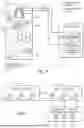
By way of further example, FIG. 5 generally shows the refrigerant detection and mitigation control board 112 connected between the thermostat 54 and the main control board 110 with wires 132 and 134 in accordance with one embodiment. As presently depicted, the wires 132 connect terminals 136 of the refrigerant detection and mitigation control board 112 to terminals 138 of the thermostat 54, and the wires 134 connect terminals 140 of the refrigerant detection and mitigation control board 112 to terminals 142 (e.g., thermostat input terminals) of the main control board 110. In at least some embodiments, including that of FIG. 5, the number of wires 132 connecting the thermostat 54 to the refrigerant detection and mitigation control board 112 is equal to the number of wires 134 connecting the main control board 110 to the refrigerant detection and mitigation control board 112, though the numbers of wires 132 and 134 may differ. And while five wires 132 and five wires 134 are shown in FIG. 5, it will be appreciated that greater or fewer wires may be used to connect the refrigerant detection and mitigation control board 112 between the thermostat 54 and the main control board 110 in other instances. The number of such wires used may depend on the functions supported by the thermostat 54 or main control board 110.
In some embodiments, each set of wires 132 and 134 includes: a wire for power (e.g., a red wire), a wire for cooling (e.g., a yellow wire), a wire for heating (e.g., a white wire), a wire for the fan (e.g., blower 32) without heating or cooling (e.g., a green wire), and a common wire (e.g., a blue or black wire). Although these wire colors are provided as examples, the wires can be provided in other or additional colors. Electrical signals may be passed along these wires 132 and 134 for various functions. Such an arrangement is generally represented in FIG. 6. In this example, power (e.g., 24-volt power) may be provided via a wire 134 from the main control board 110 to the refrigerant detection and mitigation control board 112, which may communicate this power to the thermostat 54 with a wire 132. The thermostat 54 can communicate COOL, HEAT, and FAN calls to the refrigerant detection and mitigation control board 112 over three dedicated wires 132, as indicated. That is, the thermostat 54 can generate a COOL call by applying a signal to the COOL wire 132, a HEAT call by applying a signal to the HEAT wire 132, and a FAN call by applying a signal to the FAN wire 132. These calls may be relayed by the refrigerant detection and mitigation control board 112 to the main control board 110 via three corresponding wires 134. In at least some embodiments, the thermostat 54 will use the input power (e.g., 24-volt AC power) received from the main control board 110 (via the refrigerant detection and mitigation control board 112) to initiate the COOL, HEAT, and FAN calls. This may include the thermostat 54 selectively routing (e.g., with a switch or other circuitry) the incoming input power to a corresponding COOL, HEAT, or FAN wire 132 to output the call from the thermostat 54. It will be appreciated that the refrigerant detection and mitigation control board 112 includes circuitry to allow signals to pass between terminals 136 and 140 so that signals can be communicated between wires 132 and 134.
In at least some embodiments, the refrigerant detection and mitigation control board 112 allows signals (e.g., power and COOL, HEAT, and FAN calls) over the wires 132 and 134 to freely pass between the thermostat 54 and the main control board 110 during normal operation in which a gas refrigerant is not detected with a refrigerant gas sensor 114 of the HVAC system 10. But upon detection of gas refrigerant with the refrigerant gas sensor 114, such as in the event of a refrigerant leak, the refrigerant detection and mitigation control board 112 can block some or all such communication between the thermostat 54 and the main control board 110 and instead provide one or more override signals to command operation of the HVAC system 10.
By way of further example, a method of operating the HVAC system 10 is generally represented by flowchart 150 in FIG. 7. In this embodiment, the refrigerant detection and mitigation control board 112 intercepts input commands (e.g., COOL, HEAT, or FAN calls from the thermostat 54) for the main control board 110 (block 152). If a refrigerant leak is not detected by a refrigerant gas sensor 114 (block 154), the intercepted input command is relayed by the refrigerant detection and mitigation control board 112 to the main control board 110 (block 158), which can then control an operation of the HVAC system 10 based on the relayed input command (block 158). For example, in response to a received COOL, HEAT, or FAN command, the main control board 110 may cause the blower motor 106 to drive the blower 32. The speed at which the blower 32 is driven in response to such commands may differ based on the received command. In at least some instances, the blower motor 106 is operable at more than one speed and the main control board 110 will cause the blower motor 106 to drive the blower 32 at a faster speed in response to a received COOL command than in response to a received FAN command. In response to a HEAT command, the main control board 110 may cause the blower motor 106 to drive the blower 32 the same speed as with the COOL command, the same speed as with the FAN command, or at some other speed. The main control board 110 may also control activation of the heating element 108 (e.g., controlling ignition, fuel supply, and an inducer fan to regulate combustion in a gas heating element) in response to receipt of a HEAT command.
In this manner, the HVAC commands from the thermostat 54 may be used by the main control board 110 to control one or more operations of the HVAC system 10 while refrigerant gas is not detected with the one or more refrigerant gas sensors 114. But when a refrigerant gas sensor 114 does detect (block 154) refrigerant gas outside the refrigerant circuit (i.e., a refrigerant leak), the refrigerant detection and mitigation control board 112 responds by sending an override HVAC command from the refrigerant detection and mitigation control board 112 to the main control board 110 (block 160). The main control board 110 can then control one or more operations of the HVAC system 10 based on the received override HVAC command (block 162). The override HVAC command from the refrigerant detection and mitigation control board 112 is sent to the main control board 110 in place of an HVAC command from the thermostat 54 in at least some instances. In certain other cases, the thermostat 54 may not be sending any commands for the main control board 110 (e.g., the thermostat 54 is not sending a COOL, HEAT, or FAN call) when detection of a refrigerant leak causes the refrigerant detection and mitigation control board 112 to send the override HVAC command to the main control board 110. Detecting refrigerant or a refrigerant leak can include detecting any amount of refrigerant or detecting some amount (e.g., concentration) of refrigerant that is above a set minimum threshold. That is, the refrigerant detection and mitigation control board 112 may be configured to send an override HVAC command to the main control board 110 if any refrigerant is detected by the refrigerant gas sensor 114 or may be configured to send the override HVAC command to the main control board 110 if sufficient refrigerant (e.g., above a minimum threshold) is detected by the refrigerant gas sensor 114.
After detecting refrigerant and sending an override HVAC command, the blower 32 may be operated to disperse leaked refrigerant. This may include operating the blower 32 until refrigerant is no longer detected (or is detected in an amount below a minimum threshold level) or operating the blower 32 for a predetermined amount of time (e.g., by maintaining the override HVAC command signal to the main control board 110 for five minutes, ten minutes, or some other predetermined amount of time). Additionally, in some embodiments, triggering of the override signal from the refrigerant detection and mitigation board 112 causes the indoor unit 16 to enter a lockout mode that blocks further cooling or heating with the indoor unit 16 until cleared by an operator, such as by a service technician following inspection and potential repair of the system. The lockout mode could be implemented by using the refrigerant detection and mitigation board 112 to block communication between the main control board 110 and the thermostat 54 once the override signal is triggered.
In some embodiments, one example of which is generally represented by flowchart 170 in FIG. 8, the override HVAC command is a COOL command initiated by the refrigerant detection and mitigation board 112 (rather than by the thermostat 54) and sent to the main control board 110. In this example, a refrigerant leak is detected (block 172) and, in response, the refrigerant detection and mitigation board 112 sends a COOL command (block 174) to the main control board 110. In response to this COOL command, the main control board 110 causes the blower motor 106 to drive the blower 32 (block 176). This may disperse the leaked refrigerant and reduce concentration of leaked refrigerant within the indoor unit 16.
The HVAC system 10 may be configured such that the same wire 134 can communicate the override COOL command initiated by the refrigerant detection and mitigation board 112 or a COOL command from the thermostat 54 that is relayed to the main control board 110 by the refrigerant detection and mitigation board 112 to the same thermostat input terminal 142 of the main control board 110. In turn, the main control board 110 can control operation (e.g., causing the blower motor 106 to drive the blower 32) based on the received COOL command without distinguishing between an ordinary COOL command from the thermostat 54 or an override COOL command initiated by the refrigerant detection and mitigation board 112. Among other things, this arrangement facilitates addition of the refrigerant detection and mitigation board 112 to an HVAC system 10 without replacing other components (e.g., the main control board 110 and the blower motor 106) to accommodate the functionality added by the refrigerant detection and mitigation board 112. This facilitates retrofit of an existing HVAC system 10 to add such functionality. Additionally, in at least some embodiments the refrigerant detection and mitigation board 112 is not connected to bypass control of components by the main control board 110. Rather, components (e.g., blower motor 106 and heating components) that are controlled with the main control board 110 during normal operation are still controlled with the main control board 110 when a refrigerant leak is detected. This allows safety controls of the main control board 110 (e.g., control based on inputs from a high-pressure switch, flame sensor, limit switch, and the like) to remain operable even if a refrigerant leak is detected and the refrigerant detection and mitigation board 112 sends an override command to the main control board 110.
As noted above, during ordinary operation a COOL command from the thermostat 54 may be communicated to the main control board 110 (e.g., through the refrigerant detection and mitigation control board 112) for activating the blower 32 and to the outdoor unit 14 for activating the compressor 46 and circulating refrigerant. But in at least some embodiments, including that represented in FIG. 8, the refrigerant detection and mitigation control board 112 may be used to prevent activation of the compressor 46 (block 178) and stop circulation of refrigerant to the indoor unit 16 when a refrigerant leak is detected and an override COOL command is sent from the refrigerant detection and mitigation control board 112 to the main control board 110. This may, in some instances, include interrupting input power from the main control board 110 to the thermostat 54 (e.g., by blocking power communication between the thermostat 54 and the main control board 110 within the refrigerant detection and mitigation control board 112) in response to detecting the refrigerant leak to prevent the thermostat 54 from using that power to send HVAC command signals from the thermostat 54. That is, in at least some embodiments, blocking power to the thermostat 54 removes the ability of the thermostat 54 to issue HVAC commands. This prevents the thermostat 54 from issuing a command for activating components of the outdoor unit 14, such as the compressor 46, while the HVAC system 10 is being controlled with the refrigerant detection and mitigation control board 112 in response to a refrigerant leak.
More specifically, in at least some embodiments disabling power transmission from the main control board 110 to the thermostat 54 within the refrigerant detection and mitigation control board 112 in response to detecting a refrigerant leak prevents the thermostat 54 from sending an activation signal (e.g., a COOL command) to a power regulation device (e.g., the contactor 116 or other power control circuitry) of the outdoor unit 14, which prevents operating power from being supplied to the compressor 46 and other components of the outdoor unit 14. If the compressor 46 is running when a refrigerant leak is detected, disabling power transmission from the main control board 110 to the thermostat 54 within the refrigerant detection and mitigation control board 112 terminates the activation signal to the contactor 116, causing the contactor to open and the compressor 46 to be deenergized. In at least some instances, this arrangement allows a COOL command to be transmitted to the main control board 110 (i.e., an override COOL call from the refrigerant detection and mitigation board 112) upon detection of a refrigerant leak to cause the blower motor 106 to operate (e.g., at a higher fan speed for cooling, rather than a lower fan speed for a fan-only operating mode) while also ensuring that the compressor 46 remains deenergized.
Some HVAC systems include a blower that operates only when commanded to do so by a main controller, such as a furnace control board or an AHU control board. As noted above, however, in at least some embodiments the HVAC system 10 includes a blower 32 having a motor controller 128 configured (e.g., programmed with firmware stored in a memory 124) to automatically drive the blower 32 in response to a loss of communication between a main controller (e.g., the main control board 110) and the blower motor 106. This allows the blower 32 to aid dispersion of leaked refrigerant even if the main controller experiences a failure and cannot communicate with the blower motor 106.
An example of the operation of such a blower 32 is generally represented by flowchart 190 in FIG. 9. In this embodiment, the blower motor 106 receives, at the motor controller 128, a signal from the main control board 110 (block 192). The blower motor 106 may be operated based on a command from the main control board 110 (block 194). For instance, in response to a received COOL, HEAT, or FAN call, the main control board 110 may send a command signal to the motor controller 128 to drive the blower 32 and cause air flow through the indoor unit 16. The motor controller 128 generally controls motor rotation by applying power (e.g., from a power source, such as utility power) to the blower motor 106 according to a received command, such as from the main control board 110. In some instances, however, the blower motor 106 detects (via motor controller 128) loss of communication with the main control board 110 (block 196), such as in the event of a main control board failure, and automatically drives the blower 32 in response to the loss of communication (block 198). That is, the blower 32 will default to an “on” state to cause air flow through the indoor unit 16, facilitating dispersal of any leaked refrigerant, when communication with the main controller is lost. Such a blower 32 may be installed at any suitable location, such as in a furnace, in an air handler, or at some other desired location in an HVAC system.
While the aspects of the present disclosure may be susceptible to various modifications and alternative forms, specific embodiments have been shown by way of example in the drawings and have been described in detail herein. But it should be understood that the invention is not intended to be limited to the particular forms disclosed. Rather, the invention is to cover all modifications, equivalents, and alternatives falling within the spirit and scope of the invention as defined by the following appended claims.
Claims
1. A method of operating an HVAC system including a thermostat, a main control board, and a blower having a blower motor connected to be controlled by the main control board, the method comprising:
intercepting one or more HVAC commands from the thermostat before the one or more HVAC commands reach the main control board, wherein intercepting the one or more HVAC commands from the thermostat before the one or more HVAC commands reach the main control board includes receiving the one or more HVAC commands at a mitigation control board of the HVAC system;
selectively relaying the one or more HVAC commands received from the thermostat at the mitigation control board of the HVAC system to the main control board;
controlling operation of the HVAC system via the main control board based on the relayed one or more HVAC commands;
detecting a refrigerant leak in the HVAC system;
in response to detecting the refrigerant leak, sending an override HVAC command from the mitigation control board to the main control board; and
controlling operation of the HVAC system via the main control board based on the override command from the mitigation control board.
2. The method of claim 1, wherein the override HVAC command from the mitigation control board to the main control board is a COOL command.
3. The method of claim 2, wherein controlling operation of the HVAC system via the main control board based on the COOL command from the mitigation control board includes causing the blower motor to drive the blower.
4. The method of claim 3, wherein the blower motor is operable at two or more speeds including a first speed and a second speed faster than the first speed, and controlling operation of the HVAC system via the main control board based on the COOL command from the mitigation control board includes causing the blower motor to drive the blower at the second speed.
5. The method of claim 4, wherein the main control board is configured to cause the blower motor to drive the blower at the first speed in response to a FAN command.
6. The method of claim 3, wherein the mitigation control board prevents activation of the compressor when controlling operation of the HVAC system via the main control board based on the COOL command from the mitigation control board.
7. The method of claim 1, comprising interrupting power from the main control board to the thermostat in response to detecting the refrigerant leak to prevent the thermostat from using the power to send command signals from the thermostat.
8. The method of claim 1, wherein the mitigation control board is connected to a thermostat input terminal of the main control board and the override HVAC command from the mitigation control board is received by the main control board via the thermostat input terminal.
9. The method of claim 8, wherein the mitigation control board is electrically connected to intercept COOL, HEAT, and FAN commands from the thermostat and to selectively relay those commands to the main control board.
10. The method of claim 1, wherein detecting the refrigerant leak in the HVAC system occurs after controlling operation of the HVAC system via the main control board based on the relayed one or more HVAC commands.
11. An HVAC system comprising:
a furnace having a main control board and a blower;
a refrigerant circuit including:
a heat exchanger coil installed within a housing, the heat exchanger coil operable to exchange heat with air in the housing via a refrigerant passing through the heat exchanger coil; and
a compressor coupled in fluid communication with the heat exchanger coil;
a refrigerant sensor positioned outside the refrigerant circuit; and
a refrigerant detection and mitigation control board connected in communication with a thermostat and the main control board, wherein the refrigerant detection and mitigation control board is configured to receive HVAC commands issued by the thermostat and to selectively relay the received HVAC commands to the main control board based on whether the refrigerant from the refrigerant circuit is detected via the refrigerant sensor.
12. The HVAC system of claim 11, wherein the refrigerant detection and mitigation control board is configured to issue an override HVAC command and transmit the override HVAC command to the main control board in response to the detection of the refrigerant via the refrigerant sensor.
13. The HVAC system of claim 11, wherein the refrigerant detection and mitigation control board is configured to prevent communication of the HVAC commands from the thermostat to one or more components of the HVAC system in response to the detection of the refrigerant via the refrigerant sensor.
14. The HVAC system of claim 13, wherein the one or more components of the HVAC system to which the refrigerant detection and mitigation control board is configured to prevent communication of the HVAC commands from the thermostat in response to detecting of the refrigerant with the refrigerant sensor includes a power regulation device installed to control activation of the compressor.
15. The HVAC system of claim 13, wherein the refrigerant detection and mitigation control board is configured to prevent communication of the HVAC commands from the thermostat to the one or more other components of the HVAC system in response to detecting of the refrigerant with the refrigerant sensor by interrupting an input power signal used by the thermostat to send the HVAC commands.
16. The HVAC system of claim 11, wherein the blower includes a blower motor that is connected in electrical communication with the main control board to receive blower operating commands.
17. The HVAC system of claim 16, wherein the blower motor is configured to automatically drive the blower in response to loss of communication between the main control board and the blower motor.
18. An HVAC system comprising:
a blower including a blower motor configured to be connected in electrical communication with a main control board of an HVAC system to receive blower operating commands, wherein the blower motor is configured to automatically drive the blower in response to loss of communication between the main control board and the blower motor.
19. The HVAC system of claim 18, wherein the blower is installed in the HVAC system in electrical communication with the main control board.
20. The HVAC system of claim 18, wherein the HVAC system includes a furnace and the main control board is a furnace control board.
Images & Drawings included:
Sources:
- United States Patent and Trademark Office - verify current appl. status at the USPTO↗
Recent applications in this class:
- » 20260146751 2026-05-28
REFRIGERANT CAPTURE ENCLOSURE FOR HVAC SYSTEMS - » 20260126196 2026-05-07
SYSTEM AND METHOD FOR PROVIDING COOLING DURING REFRIGERANT LEAK - » 20260092715 2026-04-02
SYSTEMS AND METHODS FOR REFRIGERANT LEAKAGE DETECTION - » 20260049731 2026-02-19
HVAC SYSTEM AND METHODS OF USING THE SAME FOR LEAK DETECTION - » 20260043568 2026-02-12
AIR-CONDITIONER CONTROL SYSTEM, INFORMATION PROCESSING APPARATUS AND AIR-CONDITIONER CONTROL METHOD - » 20260016176 2026-01-15
REFRIGERANT LEAK DETECTION SYSTEM AND METHOD - » 20260002685 2026-01-01
Refrigerant Sensor Integration into Climate Control Systems - » 20250389437 2025-12-25
System and Method for Detecting a Refrigerant Leak in an HVAC System Using a Subcooling Temperature - » 20250383106 2025-12-18
HVAC System with Leak Detection and Method of Use - » 20250383105 2025-12-18
REFRIGERANT LEAK DETECTION SYSTEM