SPACE CONTROL SYSTEM, SPACE CONTROL METHOD, AND PROGRAM
US20260146754A1
2026-05-28
19/396,299
2025-11-20
Smart Summary: A space control system helps manage and analyze a specific area in space. It uses a model calculator to create a simpler version of that area based on fluid analysis. An assimilator then predicts how things are distributed in that space by combining the simplified model with real-time environmental data. Finally, an information processor looks for ways to control the space based on the predicted distribution. This system aims to improve how we understand and manage different environments in space. 🚀 TL;DR
Abstract:
A space control system includes a model calculator that generates a reduced-order model of a target space on a basis of a result of a fluid analysis of the target space, the target space being subjected to space control, an assimilator that predicts a spatial distribution of the target space by performing assimilation processing using the reduced-order model generated by the model calculator and environment data obtained by sensing the target space, and an information processor that searches for a control candidate at a time when the target space is subjected to the space control on a basis of the spatial distribution of the target space.
Inventors:
- Junichi WATANABE 4 🇯🇵 Osaka, Japan
- KEIKO TAKAHASHI 3 🇯🇵 Osaka, Japan
- TAKAYA MATSUMOTO 2 🇯🇵 Osaka, Japan
- Yuki ARAI 2 🇯🇵 Osaka, Japan
- MIZUKI FUKUSHIMA 1 🇯🇵 Osaka, Japan
- RYOTA KIKUCHI 1 🇯🇵 Aichi, Japan
- MASARU KAMADA 1 🇯🇵 Miyagi, Japan
Applicant:
Interested in similar patents?
Get notified when new applications in this technology area are published.
Classification:
F24F11/46 » CPC main
Control or safety arrangements for purposes related to the operation of the system, e.g. for safety or monitoring Improving electric energy efficiency or saving
F24F11/63 » CPC further
Control or safety arrangements characterised by the type of control or by internal processing, e.g. using fuzzy logic, adaptive control or estimation of values Electronic processing
Description
BACKGROUND
1. Technical Field
The present disclosure relates to a space control system, a space control method, and a program.
2. Description of the Related Art
Space control systems that predict a spatial state in a building provided with an air conditioning device are known. PTL 1 discloses a system that predicts performance degradation of an air conditioning device from a performance transition database storing “part load ratio-accumulated operating time” which is an accumulated operating time with respect to a part load ratio of the air conditioning device in an arbitrary period obtained in advance and “part load ratio-coefficient of performance (COP) decrease rate” in association with each other and that generates an operation pattern which optimizes long-term efficiency.
CITATION LIST
Patent Literature
- PTL 1: Unexamined Japanese Patent Publication No. 2015-203544
SUMMARY
A space control system according to an aspect of the present disclosure includes a model calculator that generates a reduced-order model of a target space on a basis of a result of a fluid analysis of the target space, the target space being subjected to space control, an assimilator that predicts a spatial distribution of the target space by performing assimilation processing using the reduced-order model generated by the model calculator and environment data obtained by sensing the target space, and an information processor that searches for a control candidate used for the space control of the target space on a basis of the spatial distribution of the target space.
A space control method according to another aspect of the present disclosure includes generating a reduced-order model of a target space on a basis of a result of a fluid analysis of the target space, the target space being subjected to space control, predicting a spatial distribution of the target space by performing assimilation processing using the reduced-order model and environment data obtained by sensing the target space, and searching for a control candidate used for the space control of the target space on a basis of the spatial distribution of the target space.
A program according to another aspect of the present disclosure is a program for causing a computer to execute the space control method.
General or specific aspects of the present disclosure may be achieved by a system, a method, an integrated circuit, a computer program, or a recording medium such as a computer-readable compact disc read-only memory (CD-ROM), or may be achieved by any combination of the system, the method, the integrated circuit, the computer program, and the recording medium.
BRIEF DESCRIPTION OF THE DRAWINGS
FIG. 1 is a block diagram illustrating configuration of a space control system according to an exemplary embodiment;
FIG. 2 is a diagram illustrating an example of a target space to be subjected to space control;
FIG. 3 is a diagram illustrating an example of data set and input to a spatial state prediction apparatus when a fluid analysis is performed;
FIG. 4 is a diagram conceptually illustrating a reduced-order model and a control reduced-order model after assimilation processing as a result of a computational fluid dynamics (CFD) analysis;
FIG. 5 is a diagram illustrating an example of information regarding operation patterns of devices;
FIG. 6 is a diagram illustrating an example of actual data regarding a part load ratio, a COP, and power consumption;
FIG. 7 is a diagram illustrating another example of the actual data regarding the part load ratio, the COP, and the power consumption;
FIG. 8 is a diagram illustrating an example of operation conditions derived by control optimization;
FIG. 9 is a diagram illustrating an example of operation conditions that can be actually operated by the devices;
FIG. 10 is a diagram illustrating an example of Pareto solutions of control candidates;
FIG. 11 is a diagram illustrating an example of a target space in a building;
FIG. 12 is a flowchart illustrating preliminary preparation for space control in the exemplary embodiment; and
FIG. 13 is a flowchart illustrating a space control method according to the exemplary embodiment.
DETAILED DESCRIPTIONS
In a conventional system, a spatial state can be predicted only from candidates of an operation pattern of an air conditioning device stored in a performance transition database, and there is a problem that prediction accuracy of a spatial state of a target space to be subjected to space control decreases.
The present disclosure provides a space control system and the like capable of suppressing a decrease in prediction accuracy of a spatial state of a target space.
An exemplary embodiment and the like will be described hereinafter with reference to the drawings. The exemplary embodiment and the like described hereinafter provide general or specific examples. Numerical values, shapes, materials, constituent elements, arrangement positions and connection modes of the constituent elements, steps, order of the steps, and the like described in the following exemplary embodiment and the like are merely examples, and not intended to limit the present disclosure. In addition, among the constituent elements in the following exemplary embodiment and the like, constituent elements not described in the independent claims will be described as optional constituent elements.
In addition, the drawings are schematic diagrams and are not necessarily strictly illustrated. In addition, in the drawings, substantially the same constituent elements will be denoted by the same reference signs, and redundant description thereof is omitted or simplified. In addition, even when the same object is illustrated in the drawings, a scale may be changed for the sake of convenience.
EXEMPLARY EMBODIMENT
[Configuration of Space Control System]
Configuration of a space control system according to an exemplary embodiment will be described with reference to the drawings.
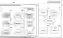
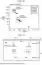
FIG. 1 is a block diagram illustrating configuration of space control system 1 according to the exemplary embodiment.
Space control system 1 is a system that predicts a state quantity of a space in a building and that searches for control candidates for performing space control in the building on the basis of the prediction.
Target space 10 to be subjected to space control is, for example, a space partitioned by walls in a building such as a house, an office, a store, a public facility, an entertainment facility, a museum, a factory, or a warehouse. A state quantity of a space is a physical quantity indicating a state of the space, and is, for example, a temperature distribution, a humidity distribution, a wind speed (including wind direction) distribution, a gas concentration distribution, and a PM2.5 (microparticulate matter) distribution of the space.
Space control system 1 includes spatial state prediction apparatus 400, one or more sensors 200, and one or more devices 300. Spatial state prediction apparatus 400 and sensors 200 and devices 300 can communicate with each other over network 100.
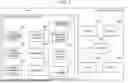
FIG. 2 is a diagram illustrating an example of target space 10 to be subjected to space control.
Each sensor 200 is a device that detects a state quantity and a boundary condition at a predetermined position in target space 10. The state quantity at the predetermined position is, for example, a temperature, humidity, wind speed, gas concentration, and the amount of PM2.5 at the predetermined position. The boundary condition at the predetermined position is an external environment that affects the state quantity of the space or a physical quantity indicating a state of a boundary region between the space and the outside. Examples of the external environment that affects the state quantity of the space include the outside air temperature, the outside wall temperature, the outside air humidity, the outside wind speed, the outside gas concentration, the amount of the outside PM2.5, and the amount of solar radiation. The state of the boundary region between the space and the outside is, for example, opening area (or an opening angle) of a door or a window provided in the building. Sensors 200 are, for example, a thermometer, a hygrometer, an anemometer, a gas concentration meter, a PM2.5 measuring device, a pyranometer, a door sensor, and a window sensor. Sensors 200 are installed in target space 10 on the basis of a result of optimization of measurement positions by measurement position optimizer 411 described later.
Detection information (sensing information) detected by sensors 200 is transmitted to spatial state prediction apparatus 400 over network 100.
Devices 300 are devices that form an environment of target space 10, and are, for example, an air conditioning device, a ventilator, an air purifier, a circulator, or a gas diffusion device. Devices 300 are provided in target space 10 of a building or in a boundary region between target space 10 and the outside. In addition, each device 300 transmits operational information including current operational conditions and an operational history to spatial state prediction apparatus 400. The operational conditions of each device 300 include physical quantities such as a temperature, humidity, an air volume, and a wind direction of air delivered from device 300. When one of devices 300 is an air conditioning device, the operational information may include information regarding a set temperature of air, a blown air volume, a sucked air volume, a rotation speed of a fan, and the amount of power supplied to a heat exchanger. When one of devices 300 is a gas diffusion device that releases a diffusing substance such as hypochlorous acid, a sterilizing ion, or a fragrance, information regarding a released gas concentration, a release amount, and a release direction of the diffusing substance may be included in the operational information.
As illustrated in FIG. 1, spatial state prediction apparatus 400 includes fluid calculation information obtainer 402, indoor information obtainer 403, control information obtainer 404, information processor 410, model calculator 406, assimilator 408, and storage 416. Information processor 410 includes measurement position optimizer 411, part load ratio obtainer 412, and COP obtainer 414. Fluid calculation information obtainer 402, indoor information obtainer 403, and control information obtainer 404 may be included in information processor 410.
Fluid calculation information obtainer 402 obtains a simulation result of a fluid analysis performed using structure information of target space 10 and control performance information of devices 300. The fluid analysis in this example is computational fluid dynamics (CFD) analysis.
The structure information of target space 10 includes information regarding a shape, size, and arrangement of target space 10, and information regarding objects arranged in target space 10 such as desks and partitions, and positions of the objects. The information regarding the shape of target space 10 is, for example, data obtained by 3D modeling target space 10 and then converting a resultant 3D model into a point cloud by a finite volume method. The structure information of target space 10 is input in advance to fluid calculation information obtainer 402 by a user or the like who uses target space 10. Note that the structure information of target space 10 may be obtained by capturing an image of target space 10 using a camera provided in devices 300.
The control performance information of devices 300 is information indicating space control capabilities of devices 300. For example, when one of devices 300 is an air conditioning device, the control performance information of device 300 is information regarding an air volume, a wind direction, and a blow-out temperature of the air conditioning device. The control performance information of devices 300 is input to fluid calculation information obtainer 402 in advance by the user or the like who uses target space 10.
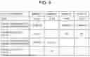
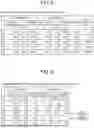
FIG. 3 is a diagram illustrating an example of data set and input to spatial state prediction apparatus 400 when a fluid analysis is performed.
FIG. 3 illustrates information regarding setting of a model for performing the fluid analysis, or more specifically, information related to a turbulence model and steady/unsteady. In addition, FIG. 3 illustrates information regarding a calculation region and mesh size, a wall boundary condition, and a thermal boundary condition as examples of the structure information of target space 10. FIG. 3 also illustrates flow boundary data as an example of the control performance information of devices 300. This drawing illustrates, as the flow boundary data, information regarding air volumes of exhaust ports of two air conditioners A1, A2, suction volumes and suction temperatures of intake ports, blow-out temperatures, air volumes, and wind directions of air conditioners A1, A2, and surface pressure and inflow temperatures at two points in gaps (spaces) of target space 10.
Spatial state prediction apparatus 400 performs a fluid analysis on the basis of the structure information of target space 10 and the control performance information of devices 300, and outputs a simulation result of the fluid analysis.
Model calculator 406 generates a reduced-order model of target space 10 on the basis of the result of the fluid analysis of target space 10. For example, model calculator 406 generates a reduced-order model using proper orthogonal decomposition (POD) from the simulation result of the fluid analysis obtained by fluid calculation information obtainer 402. The POD is a decomposition method for extracting a low-dimensional component from given multidimensional data.
FIG. 4 is a diagram conceptually illustrating a reduced-order model and a control reduced-order model after assimilation processing as a result of the CFD analysis.
A procedure for generating a reduced-order model will be described. First, variables of a physical quantity (or a state quantity) of target space 10 obtained by the CFD analysis are converted into one-dimensional information arranged in order of lattice points to create a matrix with the number of data. An average difference of the created matrix is then converted into a square matrix, a mode including eigenvalues and eigenvectors is obtained, and a POD coefficient is given to the obtained mode to reconstruct a fluid field of target space 10.
In this example, a reduced-order model in 10 modes illustrated in part (b) of FIG. 4 is generated from a result of a CFD analysis of 100 cases illustrated in part (a) of FIG. 4.
Actually, as operation conditions, there are five levels of blow-out temperature, two levels of air volume, and two levels of exhaust angle of an air conditioner, there is a case where the air conditioner is turned off, combinations of these levels are provided for each of two air conditioners, and there are two levels of temperature of wall and draft as boundary conditions. When all the combinations of these cases are executed, (5×2×2+1)2×2=882 cases are analyzed, and calculation time for predicting the spatial state becomes long. Therefore, 100 cases are extracted from the 882 cases at any intervals, and an analysis including the other 782 cases existing between the 100 cases is substituted with the reduced-order model in the 10 modes.
The reduced-order model is a model capable of maintaining essential behavior in the space control of the target space 10 while reducing dimensions thereof. By using the reduced-order model, it is possible to reduce analysis time and the amount of data of the space control.
Assimilator 408 predicts a spatial distribution of target space 10 by performing the assimilation processing using the reduced-order model generated by model calculator 406 and environment data obtained by sensing target space 10. For example, using the reduced-order model generated by model calculator 406 and the environment data of target space 10 obtained by indoor information obtainer 403, assimilator 408 determines appropriate initial values, boundary values, and parameters in such a way as to be able to reproduce a phenomenon that has occurred in the spatial distribution of target space 10. As a result, assimilator 408 generates a reduced-order model after the assimilation processing.
Measurement position optimizer 411 searches for optimal positions of sensors 200 in order to accurately predict the spatial distribution by the assimilation processing. Locations of sensors 200 that can be installed in target space 10 are restricted to locations that do not interfere with human behavior and locations without furniture. Therefore, sensor sensitivity when sensors 200 are installed at corresponding coordinates is quantified using the reduced-order model generated by model calculator 406, and a trade-off relationship regarding the number of sensors 200 and the installation locations of sensors 200 is obtained while grasping the spatial state. As a result, the number of sensors 200 and the installation locations of sensors 200 in target space 10 are optimized. An example of an optimization algorithm to be used is elitist non-dominated sorting genetic algorithm (NSGA-2) that is a multi-objective genetic algorithm.
Assimilator 408 described above obtains the environment data by changing the positions of sensors 200 provided in target space 10, and predicts spatial distributions before and after a change in the positions of sensors 200 by performing the assimilation processing using the environment data before and after the change. Information processor 410 determines the positions of sensors 200 as appropriate positions on the basis of the spatial distributions before and after the change.
Control information obtainer 404 obtains control conditions of each of simulation results obtained by fluid calculation information obtainer 402.
Information processor 410 generates a control reduced-order model by performing machine learning using the reduced-order model after the assimilation processing and the control conditions of the simulation result obtained by control information obtainer 404 (see part (c) of FIG. 4). The control reduced-order model is a model that predicts a spatial state using control conditions as input values. Information processor 410 learns a POD coefficient of a physical quantity (state quantity) of target space 10 in the reduced-order model and the control conditions of the simulation result by Gaussian process distribution to generate a prediction model of the POD coefficient using the control conditions as inputs. The control reduced-order model might be referred to as a learned reduced-order model hereinafter.
Information processor 410 thus generates the learned reduced-order model by learning the reduced-order model after the assimilation processing using the control conditions in the fluid analysis as input values. Furthermore, information processor 410 predicts the spatial distribution of target space 10 by performing the assimilation processing using the learned reduced-order model and the environment data, and searches for control candidates at a time when target space 10 is subjected to the space control on the basis of the spatial distribution. Searching for control candidates means extracting operation patterns for appropriately performing space control from among various operation patterns. Information processor 410 searches for control candidates such that target space 10 becomes close to a target spatial distribution.
The learned reduced-order model is stored in storage 416. Storage 416 also stores information regarding physical quantities (state quantities) such as a temperature desired by the user and space control (air quality control etc.). Storage 416 may store information regarding a target environmental state and the spatial distribution of target space 10.
An example in which information processor 410 obtains information regarding part load ratios, power consumption, and COPs of devices 300 and searches for control candidates on the basis of these pieces of information will be described hereinafter.
Indoor information obtainer 403 obtains environment data of target space 10 from sensors 200 whose positions have been determined by measurement position optimizer 411. Furthermore, indoor information obtainer 403 obtains operation patterns of devices 300 that perform space control (air quality control etc.) of target space 10.
FIG. 5 is a diagram illustrating an example of information regarding the operation patterns of device 300.
FIG. 5 illustrates set temperatures and set air volumes of air conditioners A1 and A2 in chronological order.
Indoor information obtainer 403 obtains information regarding power consumption and the like of devices 300 on the basis of operation patterns and the like of devices 300.
The power consumption is calculated by the following Expression 1.
Power consumption = W fan + W const ( Expression 1 )
Wfan: Amount of heat required to rotate fan, Wconst: Amount of heat required to maintain temperature of room
Wfan is derived from a relational expression between a set air volume and a measured current value in an air blowing state. Since a suction temperature and a blow-out temperature in a steady state are constant, Wconst is calculated by the following Expression 2.
W const = J ( T out - T inlet ) ( Expression 2 )
Tout: Blow-out temperature of air conditioner, Tinlet: Suction temperature of air conditioner
J can be calculated by, for example, a regression equation of the measured current value every second and (Tout−Tinlet).
The information regarding the power consumption is output to information processor 410.
Part load ratio obtainer 412 obtains part load ratios of devices 300. The part load ratio of each device 300 is calculated by the following Expression 3.
Part load ratio = ( output of air conditioning device ) / ( rated output of air conditioning device ) ( Expression 3 )
The output of the air conditioning device is calculated from a supply air volume and an inlet/outlet enthalpy difference. For example, part load ratio obtainer 412 calculates the output of the air conditioning device in the current spatial distribution by obtaining inlet/outlet enthalpy from the spatial distribution predicted by assimilator 408.
The amount of heat that is the output of the air conditioning device is calculated by the following Expression 4.
Amount of heat = ( Air specific heat × air density × supply air volume [ CMH ] × inlet / outlet enthalpy difference [ kJ / kg ] ) / 3600 [ ( kJ / h ) / kW ] ( Expression 4 )
COP obtainer 414 derives the COPs of devices 300. The COP is also called a coefficient of performance (coefficient of operation) and is a coefficient for checking energy consumption efficiency of a cooling and heating appliance. The COP is calculated by the following Expression 5.
COP = ( output of air conditioning device ) / ( power consumption of air conditioning device ) ( Expression 5 )
Storage 416 stores information regarding the power consumption obtained from indoor information obtainer 403, the part load ratios obtained by part load ratio obtainer 412, and the COPs obtained by COP obtainer 414.
The calculation regarding the power consumption, the part load ratios, and the COPs is not necessarily executed inside spatial state prediction apparatus 400, and may be executed by a computer outside spatial state prediction apparatus 400. Indoor information obtainer 403 may obtain information regarding calculation results of the power consumption from an external computer. Part load ratio obtainer 412 may obtain information regarding calculation results of the part load ratios from an external computer. COP obtainer 414 may obtain information regarding calculation results of the COPs from an external computer.
Information processor 410 obtains information regarding the part load ratios, the power consumption, and the COPs of devices 300 that perform space control, and searches for control candidates using at least one of the power consumption and the COP as an evaluation index. The power consumption is desirably small, and the COP is desirably large.
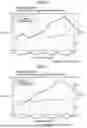
FIG. 6 is a diagram illustrating an example of actual data regarding the part load ratio, the COP, and the power consumption. FIG. 7 is a diagram illustrating another example of the actual data regarding the part load ratio, the COP, and the power consumption.
FIG. 6 illustrates actual data of air conditioner A1, and FIG. 7 illustrates actual data of air conditioner A2. In each of FIGS. 6 and 7, a horizontal axis represents the part load ratio, a left vertical axis represents the COP, and a right vertical axis represents the power consumption. Note that a scale on the right vertical axis is set such that the actual data regarding the power consumption becomes substantially smaller than the actual data regarding the COP.
As illustrated in FIGS. 6 and 7, the COP increases as the part load ratio increases, but conversely decreases when the part load ratio becomes too high. In addition, the power consumption remains somewhat constant in a predetermined range after the part load ratio slightly increases, but when the part load ratio becomes too high, the power consumption increases accordingly.
Information processor 410 searches for control candidates on the basis of the actual data illustrated in FIGS. 6 and 7. For example, information processor 410 sets the part load ratio at a time when a difference between the COP and the power consumption becomes maximum as an optimum part load ratio (see FIGS. 6 and 7), and sets operation patterns for achieving this part load ratio as the control candidates.
Information processor 410 may derive power consumption at a time when the COP is maximized, and then, when this power consumption is in an allowable range, determine a part load ratio corresponding to the maximum COP as the optimum part load ratio and set operation patterns for achieving this part load ratio as the control candidates.
Information processor 410 thus derives the part load ratio at a time when the difference between the power consumption and the COP becomes maximum, and searches for control candidates capable of maintaining the part load ratio.
Information processor 410 may derive a part load ratio at a time when the difference between the power consumption and the COP is larger than or equal to a predetermined threshold and a change in the difference between the power consumption and the COP with respect to a change in the part load ratio is within a predetermined range, and search for control candidates capable of maintaining the part load ratio.
Furthermore, when searching for control candidates, information processor 410 obtains a spatial distribution by reconstructing a space from the predicted POD coefficient using a multi-objective genetic algorithm, and optimizes control conditions at a time when devices 300 are operated.
FIG. 8 is a diagram illustrating an example of operation conditions derived by control optimization. FIG. 9 is a diagram illustrating an example of operation conditions that can be actually operated by devices 300.
The operation conditions obtained by the control optimization are selected from continuous values, whereas the operation conditions that can be actually operated are determined in advance by specification of devices 300. Therefore, it is necessary to form operation patterns by converting the operation conditions derived by the control optimization into the operation conditions that can be actually operated. Control condition 1 and control condition 2 illustrated in FIG. 9 are control conditions obtained by converting the operation conditions derived by the control optimization into the operation conditions that can be actually operated.
FIG. 10 is a diagram illustrating an example of Pareto solutions of control candidates.
In FIG. 10, a horizontal axis represents comfort, and a vertical axis represents power consumption. The comfort is, for example, a ratio of a time during which a target spatial distribution can be achieved in entire operation time.
Control condition 1 is a result of comfort and power consumption at a time when two air conditioners are operated, and control condition 2 is a result of comfort and power consumption at a time when one air conditioner is operated. In this drawing, two control conditions having similar comfort indices and greatly different power consumption are extracted by the control optimization. Information processor 410 lists and outputs the two control conditions as control candidates.
For example, space control system 1 may display a plurality of listed control candidates on an information terminal (for example, a smartphone or a tablet terminal) owned by the user. In addition, space control system 1 may control operation of devices 300 with the control candidate having the highest priority among the plurality of listed control candidates.
Space control system 1 according to the present exemplary embodiment includes model calculator 406 that generates a reduced-order model of target space 10 to be subjected to space control on a basis of a result of a fluid analysis of target space 10, assimilator 408 that predicts a spatial distribution of target space 10 by performing assimilation processing using the reduced-order model generated by model calculator 406 and environment data obtained by sensing target space 10, and information processor 410 that searches for a control candidate at a time when target space 10 is subjected to the space control on a basis of the spatial distribution of target space 10.
By generating the reduced-order model of target space 10, performing the assimilation processing using the reduced-order model and the environment data, and predicting the spatial distribution of target space 10, it is possible to suppress a decrease in prediction accuracy of the spatial state of target space 10. Furthermore, by searching for the control candidate for performing the space control on target space 10 on the basis of the spatial distribution of target space 10, it is possible to appropriately search for the control candidate.
[Space Control Method]
A space control method in the exemplary embodiment will be described.
FIG. 11 is a diagram illustrating an example of target space 10 in a building.
FIG. 11 is a top view of target space 10. In FIG. 11, a thermometer, a hygrometer, and an anemometer are provided in target space 10 as sensors 200 that detect the state quantity in target space 10. As devices 300 that form the environment of target space 10, air conditioner A1, air conditioner A2, and a plurality of ventilators are provided in target space 10.
The structure information of target space 10 is, for example, drawing information of a room and information regarding positions and shapes of furniture, and the control performance information of devices 300 is, for example, operational information such as air volumes, wind directions, and blow-out temperatures of the air conditioning devices (air conditioners A1, A2). Spatial state prediction apparatus 400 executes a simulation of a fluid analysis using these pieces of information.
FIG. 12 is a flowchart illustrating preliminary preparation for the space control in the exemplary embodiment.
FIG. 12 illustrates steps required as the preliminary preparation before executing the space control. The simulation is performed under a plurality of control conditions.
First, spatial state prediction apparatus 400 sets control ranges of control factors (step S100). For example, spatial state prediction apparatus 400 sets operation limits of devices 300 as the control ranges and sets arbitrary numerical intervals as calculation conditions. A reason why the arbitrary numerical intervals are set is that a huge amount of calculation is caused when the simulation is performed in all control patterns.
Therefore, spatial state prediction apparatus 400 determines a control pattern to be calculated (step S102). For example, spatial state prediction apparatus 400 performs random sampling on a Latin superlattice and determines the control pattern to be calculated.
Spatial state prediction apparatus 400 executes a simulation with the control pattern determined in step S102 and obtains a calculation result (step S104).
Spatial state prediction apparatus 400 generates a reduced-order model using eigenorthogonal decomposition on the basis of a physical quantity under each operation condition obtained from the calculation result in step S104 (step S106).
Spatial state prediction apparatus 400 also optimizes the positions of sensors 200 in target space 10 (step S108). For example, spatial state prediction apparatus 400 quantifies sensor sensitivity in a case where sensors 200 are installed at corresponding coordinates in target space 10 from the reduced-order model generated in step S106 and obtains a trade-off relationship between the number of sensors and grasping of an airflow state to determine the number and positions of sensors 200. Note that step S108 can be omitted when the sensor sensitivity is already sufficient.
Spatial state prediction apparatus 400 performs data assimilation processing in test operations, and predicts a spatial state of target space 10 (step S110). For example, in order to obtain optimum part load ratios, spatial state prediction apparatus 400 performs the test operations under different control conditions and different outdoor temperature conditions, and obtains information regarding the state quantity of target space 10 from sensors 200 whose positions have been determined in step S108. The state quantity is at least one of temperature, humidity, air volume, and wind direction. Spatial state prediction apparatus 400 performs the data assimilation processing using the state quantity obtained in step S110 and the reduced-order model generated in step S106, and predicts the spatial state under each control condition.
Next, spatial state prediction apparatus 400 generates a control reduced-order model (step S112). For example, spatial state prediction apparatus 400 uses the reduced-order model generated in step S106 and the control conditions in the calculation result obtained in step S104 to generate the control reduced-order model that is a prediction model of a POD coefficient with the control conditions as input values. The control reduced-order model is an example of a learned reduced-order model.
In addition, spatial state prediction apparatus 400 sets constraint conditions of the part load ratios (step S114). For example, spatial state prediction apparatus 400 plots actual data of the part load ratios and the COPs of devices 300 and actual data of the part load ratios and the power consumption of devices 300 using a spatial distribution under each predicted control condition, and extracts the optimum part load ratios. The derived optimum part load ratios are imposed as constraint conditions when searching for control candidates. Step S114 may be executed simultaneously with step S112.
FIG. 13 is a flowchart illustrating the space control method according to the exemplary embodiment.
FIG. 13 illustrates steps executed by space control system 1.
Space control system 1 obtains current control information of devices 300 in target space 10 (step S200). The control information includes time series data indicating an operation time of each control pattern and the like in addition to the control conditions illustrated in FIG. 5.
Space control system 1 obtains the state quantity of target space 10 (step S202). Specifically, space control system 1 obtains the environment data from sensors 200 whose positions have been determined in step S108 of FIG. 12 over network 100.
Space control system 1 predicts the spatial state of target space 10 (step S204). For example, space control system 1 predicts the spatial distribution using the control reduced-order model generated in step S112 of FIG. 12 with the control information obtained in step S200 as input values.
In addition, space control system 1 obtains the part load ratios and the COPs of devices 300 using the predicted spatial distribution (step S206). In addition, space control system 1 obtains the power consumption of devices 300.
Space control system 1 searches for control candidates on the basis of the part load ratios, the COPs, the power consumption, and the like obtained in step S206 (step S208).
Space control system 1 outputs information regarding the extracted control candidates (step S210). For example, space control system 1 may set an operation pattern of the optimum part load ratios as a control candidate and display the control candidate on the information terminal owned by the user. For example, space control system 1 may control the operation of devices 300 with the operation pattern of the optimum part load ratios.
By executing the above steps, it is possible to search for control candidates that achieve both comfort and energy saving.
(Conclusion)
A space control system and the like according to one aspect of the present disclosure will be described.
Space control system 1 in Example 1 includes model calculator 406 that generates a reduced-order model of target space 10 on a basis of a result of a fluid analysis of target space 10, the target space 10 being subjected to space control, assimilator 408 that predicts a spatial distribution of target space 10 by performing assimilation processing using the reduced-order model generated by model calculator 406 and environment data obtained by sensing target space 10, and information processor 410 that searches for a control candidate used for the space control of the target space on a basis of the spatial distribution of target space 10.
By performing the assimilation processing using the reduced-order model of target space 10 and the environment data and predicting the spatial distribution of target space 10, it is possible to suppress a decrease in the prediction accuracy of the spatial state of target space 10. Furthermore, by searching for the control candidate for performing the space control on target space 10 on the basis of the spatial distribution of target space 10, it is possible to appropriately search for the control candidate.
Space control system 1 in Example 2 is the space control system according to Example 1, in which information processor 410 generates a learned reduced-order model by learning the reduced-order model after the assimilation processing with a control condition in the fluid analysis as an input value, predicts the spatial distribution of target space 10 by performing the assimilation processing using the learned reduced-order model and the environment data, and searches for the control candidate on a basis of the spatial distribution.
By performing the assimilation processing using the learned reduced-order model and the environment data and predicting the spatial distribution of target space 10, it is possible to suppress a decrease in the prediction accuracy of the spatial state of target space 10.
Space control system 1 in Example 3 is the space control system according to Example 1, in which information processor 410 searches for the control candidate to allow target space 10 to become close to a target spatial distribution.
By searching for the control candidate in such a way as to become close to the target spatial distribution, it is possible to appropriately search for the control candidate.
Space control system 1 in Example 4 is the space control system according to any one of Examples 1 to 3, in which assimilator 408 changes a position of sensor 200 provided in target space 10 to obtain the environment data, and predicts spatial distributions before and after the change by performing the assimilation processing using the environment data before and after the position of sensor 200 is changed, and information processor 410 determines the position of sensor 200 on a basis of the spatial distributions before and after the change.
With this configuration, sensor 200 can be disposed at an appropriate position in target space 10. As a result, it is possible to suppress a decrease in the prediction accuracy of the spatial state of target space 10.
Space control system 1 in Example 5 is the space control system according to Example 2, in which information processor 410 obtains information regarding a part load ratio, power consumption, and a COP of device 300 that performs the space control, and searches for the control candidate using at least one of the power consumption and the COP as an evaluation index.
By searching for the control candidate using at least one of the power consumption and the COP as the evaluation index, it is possible to appropriately search for the control candidate.
Space control system 1 in Example 6 is the space control system according to Example 5, in which information processor 410 derives the part load ratio which maximizes a difference between the power consumption and the COP, and searches for the control candidate capable of maintaining the part load ratio.
With this configuration, for example, information regarding an optimum part load ratio can be obtained, and the control candidate can be appropriately searched for.
Space control system 1 in Example 7 is the space control system according to Example 5, in which information processor 410 derives the part load ratio which causes a difference between the power consumption and the COP to be larger than or equal to a predetermined threshold and a change in the difference between the power consumption and the COP with respect to a change in the part load ratio to be within a predetermined range, and searches for the control candidate capable of maintaining the part load ratio.
With this configuration, it is possible to obtain information regarding a part load ratio resistant to disturbance and appropriately search for the control candidate.
A space control method in Example 8 includes the steps of generating a reduced-order model of target space 10 on a basis of a result of a fluid analysis of target space 10, the target space 10 being subjected to space control, predicting a spatial distribution of target space 10 by performing assimilation processing using the reduced-order model and environment data obtained by sensing target space 10, and searching for a control candidate used for the space control of the target space on a basis of the spatial distribution of target space 10.
By performing the assimilation processing using the reduced-order model of target space 10 and the environment data and predicting the spatial distribution of target space 10, it is possible to suppress a decrease in the prediction accuracy of the spatial state of target space 10. Furthermore, by searching for the control candidate for performing the space control on target space 10 on the basis of the spatial distribution of target space 10, it is possible to appropriately search for the control candidate.
A program in Example 9 is a program for causing a computer to execute the space control method according to Example 8.
With this configuration, it is possible to achieve a space control method capable of suppressing a decrease in the prediction accuracy of the spatial state of target space 10.
Other Exemplary Embodiments
Although the space control system and the like in the present disclosure have been described above on the basis of the exemplary embodiment, the present disclosure is not limited to the exemplary embodiment. The exemplary embodiment to which various modifications conceivable by those skilled in the art are applied and other modes constructed by combining some constituent elements in the exemplary embodiment are also included in the scope of the present disclosure without departing from the gist of the present disclosure.
Although an example in which spatial state prediction apparatus 400 and devices 300 are connected via a communication network has been described above, the present disclosure is not limited thereto. For example, spatial state prediction apparatus 400 may be provided inside devices 300. In this case, sensors 200 may also be provided in devices 300 and connected to spatial state prediction apparatus 400 inside devices 300.
The spatial state prediction apparatus in the above exemplary embodiment is achieved by, as a hardware configuration, a nonvolatile memory storing a program, a volatile memory that is a temporary storage area for executing the program, input/output ports, a communication interface, a processor for executing the program, and the like. Each constituent element of the spatial state prediction apparatus is achieved by the processor that executes the program stored in the memory. The spatial state prediction apparatus may be achieved by a stationary personal computer (PC), a portable terminal such as a smartphone or a tablet, a dedicated computer, or the like, may be achieved by a server (for example, a cloud server), or may be achieved by a combination thereof.
In addition, each constituent element may be configured by dedicated hardware or may be achieved by executing a software program suitable for the constituent element. Each constituent element may be achieved by causing a program executer, such as a CPU or a processor, to read and execute the software program stored in a recording medium, such as a hard disk or a semiconductor memory.
Furthermore, the order in which the steps in each flowchart are executed is for specifically describing the present disclosure, and may be an order other than the above. In addition, some of the steps may be executed simultaneously (in parallel) with other steps, or some of the steps need not be executed.
The division of the functional blocks in the block diagram is an example, and a plurality of functional blocks may be implemented as one functional block, one functional block may be divided into a plurality of functional blocks, or some functions may be transferred to another functional block. Then, functions of a plurality of functional blocks having similar functions may be processed in parallel or in a time division manner by single hardware or software.
In addition, the spatial state prediction apparatus according to the above exemplary embodiment may be achieved as a single device or may be achieved by a plurality of devices. When the spatial state prediction apparatus is achieved by a plurality of apparatuses, each constituent element included in the spatial state prediction apparatus may be distributed to the plurality of apparatuses in any manner. When the spatial state prediction apparatus is achieved by a plurality of apparatuses, a communication method used between the plurality of apparatuses is not particularly limited, and may be wireless communication or wired communication. In addition, wireless communication and wired communication may be combined between the apparatuses.
In addition, each constituent element described in the above exemplary embodiment may be achieved as software, or may be typically achieved as a large-scale integration (LSI) circuit that is an integrated circuit. The constituent elements may each be integrated into one chip, or some or all of the constituent elements may be integrated into one chip. The LSI referred to herein may also be called IC, system LSI, super LSI, or ultra LSI depending on a degree of integration. The circuit integration method is not limited to LSI, and may be implemented by a dedicated circuit (a general-purpose circuit that executes a dedicated program) or a general-purpose processor. A field-programmable gate array (FPGA) that can be programmed after manufacture of the LSI circuit or a reconfigurable processor in which connections and settings of circuit cells disposed inside the LSI circuit can be reconfigured may be used. Furthermore, if a circuit integration technology replacing LSI appears due to progress of semiconductor technologies or other derived technologies, the constituent elements may be integrated using the technology.
A system LSI is a super multifunctional LSI manufactured by integrating a plurality of processors on one chip, and is specifically a computer system including a microprocessor, a read-only memory (ROM), a random-access memory (RAM), and the like. The ROM stores a computer program. The microprocessor operates according to the computer program to allow the system LSI to achieve its functions.
In addition, another aspect of the present disclosure may be a computer program that causes a computer to execute characteristic steps included in a method of using a battery pack.
Furthermore, for example, the program may be a program to be executed by a computer. Furthermore, another aspect of the present disclosure may be a non-transitory computer-readable recording medium storing such a program. For example, such a program may be stored in a recording medium and distributed or circulated. For example, the distributed program is installed in another apparatus including a processor, and the program is executed by the processor, so that the apparatus can execute the above processes.
With the space control system and the like of the present disclosure, it is possible to suppress a decrease in the prediction accuracy of the space control of the target space.
The present disclosure can be applied to a space control system capable of suppressing a decrease in prediction accuracy of space control of a target space.
Claims
What is claimed is:1. A space control system comprising:
a model calculator that generates a reduced-order model of a target space on a basis of a result of a fluid analysis of the target space, the target space being subjected to space control;
an assimilator that predicts a spatial distribution of the target space by performing assimilation processing using the reduced-order model generated by the model calculator and environment data obtained by sensing the target space; and
an information processor that searches for a control candidate used for the space control of the target space on a basis of the spatial distribution of the target space.
2. The space control system according to claim 1, wherein the information processor
generates a learned reduced-order model by learning the reduced-order model after the assimilation processing with a control condition in the fluid analysis as an input value,
predicts the spatial distribution of the target space by performing the assimilation processing using the learned reduced-order model and the environment data, and
searches for the control candidate on a basis of the spatial distribution.
3. The space control system according to claim 1, wherein the information processor searches for the control candidate to allow the target space to become close to a target spatial distribution.
4. The space control system according to claim 1, wherein
the assimilator
changes a position of a sensor provided in the target space to obtain the environment data, and
predicts spatial distributions before and after the change by performing the assimilation processing using the environment data before and after the position of the sensor is changed, and
the information processor determines the position of the sensor on a basis of the spatial distributions before and after the change.
5. The space control system according to claim 2, wherein
the information processor
obtains information regarding a part load ratio, power consumption, and a coefficient of performance (COP) of a device that performs the space control, and
searches for the control candidate using at least one of the power consumption and the COP as an evaluation index.
6. The space control system according to claim 5, wherein
the information processor
derives the part load ratio which maximizes a difference between the power consumption and the COP, and
searches for the control candidate capable of maintaining the part load ratio.
7. The space control system according to claim 5, wherein
the information processor
derives the part load ratio which causes
a difference between the power consumption and the COP to be larger than or equal to a predetermined threshold and
a change in the difference between the power consumption and the COP with respect to a change in the part load ratio to be within a predetermined range, and
searches for the control candidate capable of maintaining the part load ratio.
8. A space control method comprising:
generating a reduced-order model of a target space on a basis of a result of a fluid analysis of the target space, the target space being subjected to space control;
predicting a spatial distribution of the target space by performing assimilation processing using the reduced-order model and environment data obtained by sensing the target space; and
searching for a control candidate used for the space control of the target space on a basis of the spatial distribution of the target space.
9. A program for causing a computer to execute the space control method according to claim 8.
Images & Drawings included:


Sources:
- United States Patent and Trademark Office - verify current appl. status at the USPTO↗
Similar patent applications:
- » 20230114755
Virtual space control system, method for controlling the same, and control program - » 9526483
Virtual space control data receiving apparatus,virtual space control data transmission and reception system, virtual space control data receiving method, and virtual space control data receiving program storage media - » 20260131277
AN AIR TREATMENT SYSTEM FOR PROVIDING TREATED AIR IN A DEFINED SPACE, A METHOD FOR CONTROLLING AN AIR TREATMENT SYSTEM AND A COMPUTER PROGRAM FOR AN AIR TREATMENT SYSTEM - » 20100031261
VIRTUAL SPACE PROVIDING SYSTEM, METHOD FOR CONTROLLING IMAGE FORMING APPARATUS, AND MEDIUM STORING PROGRAM THEREOF - » 20090254747
Method, system, and computer program product for providing e-token based access control for virtual world spaces - » 20240053950
Display control system, display control method, and recording medium recording a display control program for displaying user icons in a virtual space - » 20140354687
Computer-readable non-transitory storage medium having stored therein information processing program, information processing system, information processing apparatus, and information processing method for controlling movement of a virtual camera in a game space - » 20120310610
Program, information storage medium, information processing system, and information processing method for controlling a movement of an object placed in a virtual space - » 20150355814
Non-transitory storage medium encoded with computer readable information processing program, information processing apparatus, method of controlling information processing apparatus, and information processing system, capable of controlling virtual camera while grasping overall condition of virtual camera arranged in virtual space
Recent applications in this class:
- » 20260146753 2026-05-28
TECHNIQUES FOR ENERGY MANAGEMENT OF CLIMATE CONTROL SYSTEMS - » 20260139861 2026-05-21
OFFICE ENVIRONMENT CONTROL SYSTEM, OFFICE ENVIRONMENT CONTROL METHOD, AND RECORDING MEDIUM - » 20260118004 2026-04-30
HEATING, VENTILATION AND AIR-CONDITIONING (HVAC) SYSTEM BATTERY TRANSFER SWITCH - » 20260118003 2026-04-30
SYSTEMS AND METHODS FOR OPERATING HVAC SYSTEMS FROM STORED ENERGY - » 20260092716 2026-04-02
CONTROL METHOD FOR A HYDRONIC SYSTEM - » 20260085848 2026-03-26
SYSTEM AND METHODS FOR DYNAMICALLY ALLOCATING VOLTAGE IN A COMPRESSOR MOTOR - » 20260071771 2026-03-12
OPTIMIZED CONTROL METHOD AND SYSTEM OF BUILDING AIR CONDITIONINGS TAKING PERSONALIZED COMFORT OF REGIONAL USERS INTO CONSIDERATION - » 20260055911 2026-02-26
ENERGY OPTIMIZATION FOR HEATING, VENTILATION, AND AIR-CONDITIONING (HVAC) - » 20250369639 2025-12-04
OPTIMIZATION OF BUILDING OPERATIONS - » 20250362044 2025-11-27
METHODS AND SYSTEMS FOR DETERMINING FINANCIAL LOSSES IN HEATING, VENTILATION, AND AIR CONDITIONING (HVAC) SYSTEM