FILTER AND AEROSOL GENERATING ARTICLE INCLUDING THE FILTER
US20260150893A1
2026-06-04
19/349,118
2025-10-03
Smart Summary: A new type of filter is designed for devices that create aerosols. It is made from cellulose acetate fibers and contains a special material inside that helps absorb unwanted substances. The filter is wrapped in a protective layer to keep everything together. After being made, this filter produces very little acetic acid or citric acid when kept at room temperature for a month. The amount of acid released is very low, ensuring it is safer for use. 🚀 TL;DR
Abstract:
Provided is a filter for an aerosol generating article, the filter including a filter tow including cellulose acetate fibers, at least one adsorbent arranged inside the filter tow, and a filter wrapper surrounding the filter tow, wherein a weight of acetic acid or citric acid produced in the filter at a temperature of 25° C. for one month after manufacturing the filter is 0.1 mg/mm or less based on a length of the filter.
Assignee:
- KT&G CORPORATION 1,095 🇰🇷 Daejeon, South Korea
Applicant:
Interested in similar patents?
Get notified when new applications in this technology area are published.
Classification:
A24D3/16 » CPC main
Tobacco smoke filters, e.g. filter-tips, filtering inserts; Filters specially adapted for simulated smoking devices; Mouthpieces for cigars or cigarettes; Use of materials for tobacco smoke filters of inorganic materials
A24D1/045 » CPC further
Cigars; Cigarettes with mouthpieces or filter-tips with smoke filter means
A24D1/20 » CPC further
Cigars; Cigarettes Cigarettes specially adapted for simulated smoking devices
A24D3/10 » CPC further
Tobacco smoke filters, e.g. filter-tips, filtering inserts; Filters specially adapted for simulated smoking devices; Mouthpieces for cigars or cigarettes; Use of materials for tobacco smoke filters of organic materials as carrier or major constituent of cellulose or cellulose derivatives
A24D3/163 » CPC further
Tobacco smoke filters, e.g. filter-tips, filtering inserts; Filters specially adapted for simulated smoking devices; Mouthpieces for cigars or cigarettes; Use of materials for tobacco smoke filters of inorganic materials Carbon
A24D3/166 » CPC further
Tobacco smoke filters, e.g. filter-tips, filtering inserts; Filters specially adapted for simulated smoking devices; Mouthpieces for cigars or cigarettes; Use of materials for tobacco smoke filters of inorganic materials Silicic acid or silicates
A24D3/17 » CPC further
Tobacco smoke filters, e.g. filter-tips, filtering inserts; Filters specially adapted for simulated smoking devices; Mouthpieces for cigars or cigarettes Filters specially adapted for simulated smoking devices
A24D1/04 IPC
Cigars; Cigarettes with mouthpieces or filter-tips
Description
CROSS-REFERENCE TO RELATED APPLICATION
This application is based on and claims priority under 35 U.S.C. § 119 to Korean Patent Application No. 10-2024-0177570, filed on Dec. 3, 2024, in the Korean Intellectual Property Office, the disclosure of which is incorporated by reference herein in its entirety.
BACKGROUND
1. Field
The disclosure relates to a filter and an aerosol generating article including the filter, and more particularly, to a filter including an adsorbent having excellent adsorption performance and an aerosol generating article including the filter.
2. Description of the Related Art
As a filter used in a cigarette (or an ‘aerosol generating article’), there is a growing demand for a composite filter which additionally includes a heterogeneous material other than a filter material. The heterogeneous material may include an adsorbent such as activated carbon or the like, and the adsorbent may adsorb gaseous materials passing through the filter.
SUMMARY
The adsorption performance of an adsorbent included in a filter may be related to the specific surface area of the adsorbent. As the specific surface area of the adsorbent increases, the adsorbent may adsorb a material to be adsorbed more smoothly, and as the specific surface area of the adsorbent decreases, the adsorption performance for the material to be adsorbed may decrease. In the case of a filter including an adsorbent in the related art, the specific surface area of the adsorbent decreases during a manufacturing process of the filter and/or during storage of the filter.
The technical problems to be solved by the embodiments of the disclosure are not limited to the above-described problems, and problems that are not mentioned will be clearly understood by those of ordinary skill in the art from the disclosure and the accompanying drawings.
Additional aspects will be set forth in part in the description which follows and, in part, will be apparent from the description, or may be learned by practice of the presented embodiments of the disclosure.
According to an embodiment, a filter for an aerosol generating article may include a filter tow including cellulose acetate fibers, at least one adsorbent arranged inside the filter tow, and a filter wrapper surrounding the filter tow, and a weight of acetic acid or citric acid produced in the filter at a temperature of 25° C. for one month after manufacturing the filter may be 0.1 mg/mm or less based on a length of the filter.
According to another embodiment, an aerosol generating article may include a filter and an aerosol generating rod generating aerosols by heating or combustion.
BRIEF DESCRIPTION OF THE DRAWINGS
The above and other aspects, features, and advantages of certain embodiments of the disclosure will be more apparent from the following description taken in conjunction with the accompanying drawings, in which:
FIG. 1 is a block diagram of an aerosol-generating device according to an embodiment;
FIG. 2A shows an aerosol-generating device according to an embodiment;
FIG. 2B shows an aerosol-generating device according to an embodiment;
FIG. 3 shows an aerosol-generating device according to an embodiment;
FIG. 4 shows an aerosol generating article according to an embodiment;
FIG. 5 shows an aerosol generating article according to an embodiment;
FIG. 6 shows an aerosol generating article according to an embodiment;
FIG. 7 shows an aerosol generating article according to an embodiment; and
FIG. 8 shows a filter for an aerosol generating article according to an embodiment.
DETAILED DESCRIPTION
Hereinafter, the embodiments disclosed in the present specification will be described in detail with reference to the accompanying drawings. The same or similar elements are denoted by the same reference numerals even though they are depicted in different drawings, and redundant descriptions thereof will be omitted. With regard to the description of the drawings, similar reference numerals may be used to refer to similar or related elements.
In the following description, with respect to constituent elements used in the following description, the suffixes “module” and “unit” are used only in consideration of facilitation of description, and do not have mutually distinguished meanings or functions. As used herein, the suffix “module” or “unit” may include a unit implemented in hardware, software, or firmware, and may be used interchangeably with other terms, for example, “logic,” “logic block,” “part,” or “circuitry.” On the other hand, when a component is referred to as being “directly connected to” or “directly coupled to” another component, there are no intervening components present. As used herein, the singular form is intended to include the plural forms as well, unless the context clearly indicates otherwise. Various embodiments of the present disclosure may be implemented as software including one or more instructions stored in a storage medium (e.g., a memory 17) readable by a machine (e.g., an aerosol generating device 1). For example, a processor (e.g., a controller 12) of the machine (e.g., the aerosol generating device 1) may call at least one instruction among one or more instructions stored from the storage medium and execute the at least one instruction. This makes it possible for the machine to be operated to perform at least one function according to the called at least one instruction. Examples of the one or more instructions may include codes created by a compiler, or codes executable by an interpreter. A machine-readable storage medium may be provided as a non-transitory storage medium. For example, the “module” or the “unit” may be implemented in the form of an application-specific integrated circuit (ASIC).
In addition, in the following description of the embodiments disclosed in the present specification, a detailed description of known functions and configurations incorporated herein will be omitted when the same may make the subject matter of the embodiments disclosed in the present specification rather unclear. In addition, the accompanying drawings are provided only for a better understanding of the embodiments disclosed in the present specification and are not intended to limit the technical ideas disclosed in the present specification. Therefore, it should be understood that the accompanying drawings include all modifications, equivalents, and substitutions within the scope and spirit of the present disclosure.
It will be understood that although the terms “first”, “second”, etc., may be used herein to describe various components, these components should not be limited by these terms. These terms are only used to distinguish one component from another component.
It will be understood that when a component is referred to as being “connected to” or “coupled to” another component, it may be directly connected to or coupled to another component, or intervening components may be present. On the other hand, when a component is referred to as being “directly connected to” or “directly coupled to” another component, there are no intervening components present.
As used herein, the singular form is intended to include the plural forms as well, unless the context clearly indicates otherwise.
Various embodiments of the present disclosure may be implemented as software including one or more instructions stored in a storage medium (e.g., a memory 17) readable by a machine (e.g., an aerosol generating device 1). For example, a processor (e.g., a controller 12) of the machine (e.g., the aerosol generating device 1) may call at least one instruction among one or more instructions stored from the storage medium and execute the at least one instruction. This makes it possible for the machine to be operated to perform at least one function according to the called at least one instruction. Examples of the one or more instructions may include codes created by a compiler, or codes executable by an interpreter. A machine-readable storage medium may be provided as a non-transitory storage medium. According to an embodiment, the sensor unit 13 may sense a state of the aerosol generating device 1 or a state of the surroundings of the aerosol generating device 1 and may transmit information corresponding to the sensed state to the controller 12. For example, the sensor unit 13 may include a temperature sensor, a puff sensor, an insertion detection sensor, a reuse detection sensor, an overwetting detection sensor, a cigarette identification sensor, a cartridge detection sensor, a cap detection sensor, and/or a movement detection sensor. The sensor unit 13 may further include various sensors, such as a liquid remaining amount sensor for detecting the liquid remaining amount of a cartridge and an immersion sensor for detecting immersion of the aerosol generating device 1. According to an embodiment, the temperature sensor may detect the heating temperature of the heater 18 or CH.
In the present disclosure, a direction of the aerosol generating device 1 may be defined based on an orthogonal coordinate system. The x-axis direction in the orthogonal coordinate system may be defined as a left-right direction of the aerosol generating device 1. The y-axis direction may be defined as a front-back direction of the aerosol generating device 1. The z-axis direction may be defined as an upward and downward direction of the aerosol generating device 1.
FIG. 1 is a block diagram of the aerosol generating device 1 according to an embodiment.
According to an embodiment, the aerosol generating device 1 may include a power supply 11, the controller 12, a sensor unit 13, an output unit 14, an input unit 15, a communication unit 16, a memory 17, and/or heater 18 or CH. However, it may be understood by those skilled in the art that some of the components shown in FIG. 1 may be omitted or new components may be added, according to the design of the aerosol generating device 1.
According to an embodiment, the sensor unit 13 may sense a state of the aerosol generating device 1 or a state of the surroundings of the aerosol generating device 1 and may transmit information corresponding to the sensed state to the controller 12. For example, the sensor unit 13 may include a temperature sensor, a puff sensor, an insertion detection sensor, a reuse detection sensor, an overwetting detection sensor, a cigarette identification sensor, a cartridge detection sensor, a cap detection sensor, and/or a movement detection sensor. The sensor unit 13 may further include various sensors, such as a liquid remaining amount sensor for detecting the liquid remaining amount of a cartridge and an immersion sensor for detecting immersion of the aerosol generating device 1.
According to an embodiment, the temperature sensor may detect the heating temperature of the heater 18 or CH. The aerosol generating device 1 may include a separate temperature sensor for detecting respective temperatures of the heater 18 or CH, or the heater 18 or CH may serve as a temperature sensor. For example, the temperature sensor may be used to measure an impedance of the heater 18. The impedance of the heater 18 may be correlated with the temperature of the heater 18. The temperature sensor may measure a current and/or voltage applied to the heater 18 (or an induction coil). Based on the measured current and/or voltage, the impedance for the heater 18 may be calculated. The controller 12 may estimate the temperature of the heater 18, based on the calculated impedance.
For example, the temperature sensor may include a resistive element (e.g., a thermistor) whose resistance value changes in response to a change in temperatures of the heater 18 or CH. The temperature sensor may output a signal corresponding to the resistance value of the resistive element, and the controller 12 may detect the temperatures and/or temperature changes of the heater 18 or CH, based on the signal corresponding to the resistance value.
As another example, the temperature sensor may include a sensor for detecting the resistance values of the heater 18 or CH. The temperature sensor may output signals corresponding to the resistance values of the heater 18 or CH, and the controller 12 may detect the temperatures and/or temperature changes of the heater 18 or CH, based on the signals corresponding to the resistance values.
According to an embodiment, the temperature sensor may detect a temperature of the power supply 11. The temperature sensor may be disposed adjacent to the power supply 11. For example, the temperature sensor may be attached to one surface of the power supply 11 (e.g., a battery) and/or mounted on one surface of a printed circuit board. For example, the aerosol generating device 1 may include a power protection circuit module (PCM), and the temperature sensor may be disposed adjacent to the power supply 11 together with the power PCM.
According to an embodiment, the temperature sensor may be disposed inside a housing (not shown) of the aerosol generating device 1 to detect an internal temperature of the housing.
According to an embodiment, the puff sensor may detect a puff of a user.
For example, the puff sensor may include a pressure sensor. The pressure sensor may output a signal corresponding to an internal pressure of the aerosol generating device 1, and the controller 12 may detect the puff of the user, based on the signal corresponding to the internal pressure. The internal pressure of the aerosol generating device 1 may correspond to pressure of an airflow path along which gas flows. The puff sensor may be disposed to correspond to the airflow path along which gas flows, in the aerosol generating device 1.
As another example, the puff sensor may include a temperature sensor. When the user′ puff occurs, a temporary temperature drop may occur in the airflow path, a space where an aerosol generating article is inserted (hereinafter, an insertion space), the heater 18 or CH, etc. The controller 12 may detect the user's puff, based on a signal corresponding to the temperature of the airflow path, etc. output from the temperature sensor.
As another example, the puff sensor may include both a pressure sensor and a temperature sensor. In this case, the temperature sensor may measure a temperature that is used to correct an internal pressure measured by the pressure sensor. For example, the puff sensor may correct the signal corresponding to the internal pressure, based on the temperature measured by the temperature sensor, and may output the corrected signal. As another example, the puff sensor may output the signal corresponding to the temperature measured by the temperature sensor, and the signal corresponding to the internal pressure measured by the puff sensor. In this case, the controller 12 may receive the signals, and may correct the signal corresponding to the internal pressure, based on the signal corresponding to the temperature.
As another example, the puff sensor may include a capacitance sensor. In the present disclosure, the capacitance sensor may also be referred to as a cap sensor or a capacitive sensor. When the user's puff occurs, a temperature change and/or aerosol flow may occur within the insertion space of the aerosol generating article, and accordingly, an internal permittivity of the insertion space may change. The controller 12 may detect the user's puff, based on a signal corresponding to the internal permittivity, etc. of the insertion space output by the temperature sensor.
The puff sensor is not limited to the aforementioned examples, and may be implemented using various sensors for detecting the user's puff.
According to an embodiment, the insertion detection sensor may detect insertion and/or removal of the aerosol generating article. The insertion detection sensor may be provided around the insertion space. The insertion detection sensor may also include any combination of the aforementioned examples.
For example, the insertion detection sensor may include a capacitance sensor. The capacitance sensor may include at least one conductor. The at least one conductor may be arranged adjacent to the insertion space. When the aerosol generating article is inserted into or removed from the insertion space, a permittivity around the conductor may change. The controller 12 may detect the insertion and/or removal of the aerosol generating article, based on a signal corresponding to the internal permittivity, etc. of the insertion space output by the capacitance sensor.
As another example, the insertion detection sensor may include an inductive sensor. The inductive sensor may include at least one coil. The at least one coil may be disposed adjacent to the insertion space. When the aerosol generating article (e.g., a wrapper of the aerosol-generating article) includes a conductor and is inserted into or removed from the insertion space, a change in a magnetic field may occur around a coil where a current flows. The controller 12 may detect insertion and/or removal of the aerosol generating article including the conductor, based on the characteristics (e.g., a frequency, a current value, a voltage value, an inductance value, and an impedance value of an alternating current) of a current output or detected by the inductive sensor. Alternatively, the aerosol generating article (e.g., a medium portion of the aerosol generating article) may include a susceptor (SUS), etc. Even in this case, a change in the magnetic field around the coil may occur based on the insertion or removal of the susceptor, etc. within the insertion space, and the controller 12 may also detect the insertion and/or removal of the aerosol generating article, based on the characteristics of the current of the inductive sensor.
The insertion detection sensor is not limited to the aforementioned examples, and may be implemented using any of various sensors (e.g., a proximity sensor) for detecting insertion and/or removal of the aerosol generating article. The insertion detection sensor may also include any combination of the aforementioned examples. According to an embodiment, the insertion detection sensor may include a switch, etc. for detecting compression performed by the aerosol generating article.
According to an embodiment, the reuse detection sensor may detect whether the aerosol generating article is reused For example, the reuse detection sensor may be a color sensor for detecting a color of the aerosol generating article. When the aerosol generating article is used by the user, a change in the color of a portion of the wrapper surrounding the outside of the aerosol generating article may occur due to generated aerosol or heating. The color sensor may output a signal corresponding to optical characteristics (e.g., a wavelength of light) corresponding to the color of the wrapper, based on light reflected by the wrapper. When a change in the color of the portion of the wrapper is detected, the controller 12 may determine that the aerosol generating article inserted into the insertion space has already been used.
According to an embodiment, the overwetting detection sensor may detect whether the aerosol generating article is in an overwetting state. For example, the overwetting detection sensor may include a capacitance sensor. The capacitance sensor may include at least one conductor disposed adjacent to the insertion space. The controller 12 may detect whether the aerosol generating article is in an overwetting state, based on the level of a signal corresponding to a permittivity, etc. output by the capacitance sensor. For example, the controller 12 may check a level range including the level of the signal, based on a look-up table, and may determine a moisture content for the aerosol generating article, based on the checked level range.
According to an embodiment, the cigarette identification sensor may detect whether the aerosol generating article is authentic, and/or detect the type of the aerosol generating article.
For example, the cigarette identification sensor may include an optical sensor for detecting an identification material (or an identification mark) located on an outer surface (e.g., a wrapper) of the aerosol generating article. The optical sensor may radiate light toward the identification material (or the identification mark) of the aerosol generating article, and may detect the authenticity and/or the type of the aerosol generating article, based on the reflected light. For example, the identification material may include a material that emits light of a wavelength in a specific band, based on the radiated light. The controller 12 may detect the authenticity and/or the type of the aerosol generating article, based on the range of the wavelength.
As another example, the cigarette identification sensor may include a capacitance sensor. According to the types of aerosol generating article inserted into the insertion space, the internal permittivity of the insertion space may vary. The controller 12 may detect he authenticity of and/or the type of the aerosol generating article, based on the signal corresponding to the internal permittivity, etc. of the insertion space output by the capacitance sensor.
As another example, the cigarette identification sensor may include an inductive sensor. When a conductor is included in the wrapper and/or interior (e.g., a medium portion) of the aerosol generating article inserted into the insertion space, the characteristics of a current detected by the inductive sensor (e.g., a frequency, a current value, a voltage value, an inductance value, and an impedance value of an AC current) may differ according to the types of aerosol generating article inserted into the insertion space. The controller 12 may detect he authenticity of and/or the type of the aerosol generating article, based on the characteristics of a current output by the capacitance sensor or detected by the inductive sensor.
The cigarette identification sensor is not limited to the aforementioned examples, and may be implemented using any of various sensors for detecting whether the aerosol generating article is authentic, and/or detecting the type of the aerosol generating article. The cigarette identification sensor may also include any combination of the aforementioned examples.
According to an embodiment, the cartridge detection sensor may detect insertion and/or removal of the cartridge. For example, the cartridge detection sensor may include an inductive sensor, a capacitance sensor, a resistance sensor, a hall sensor (a hall IC) using a hall effect, and/or an optical sensor.
According to an embodiment, the cap detection sensor may detect insertion and/or removal of the cap. For example, the cap detection sensor may include an inductive sensor, a capacitance sensor, a resistance sensor, a hall sensor (a hall IC), and/or an optical sensor. The cap may include a structure that covers at least a portion of the cartridge mounted on or inserted into the aerosol generating device 1 or covers at least a portion of the housing of the aerosol generating device 1. When the cap is mounted on or removed from the housing, the cap detection sensor may output a signal corresponding to the mounting or removal of the cap. The controller 12 may detect the mounting or removal of the cap, based on a signal corresponding to the mounting or removal.
According to an embodiment, the movement detection sensor may detect a motion of the aerosol generating device 1. The movement detection sensor may be implemented using at least one of an acceleration sensor and a gyro sensor.
According to an embodiment, the sensor unit 13 may further include at least one of a humidity sensor, a pressure sensor, a magnetic sensor, a global positioning sensor (GPS), or a proximity sensor, in addition to the above-described sensors. Functions of the sensors would be instinctively understood by one of ordinary skill in the art in view of their names and thus detailed descriptions thereof will be omitted herein.
According to an embodiment, the output unit 14 may output information about the state of the aerosol generating device 1. The output unit 14 may include a display, a haptic unit, and/or a sound output unit, but embodiments are not limited thereto. For example, information about the aerosol generating device 1 may include a charging/discharging state of the power supply 11 of the aerosol generating device 1, preheating states of the heater 18 or CH, an insertion/removal state of the aerosol generating article and/or the cartridge, a mounting and/or removal state of the cap, or a state in which use of the aerosol generating device 1 is limited (e.g., detection of an abnormal article). The display may visually provide the information about the state of the aerosol generating device 1 to the user. For example, the display may include a light-emitting diode (LED), a liquid crystal display (LCD), an organic light-emitting diode (OLED), etc. When the display includes a touch pad, the display may also be used as an input unit 15. A haptic unit may tactually provide the information about the state of the aerosol generating device 1 to the user. For example, the haptic unit may include a vibration motor, a piezoelectric element, an electrical stimulation device, etc. The sound output unit may acoustically provide the information about the aerosol generating device 1 to the user. For example, the sound output unit may convert an electrical signal into a sound signal and may output the sound signal to the outside.
According to an embodiment, the power supply 11 may output power for operating the aerosol generating device 1. The power supply 11 may include one or more batteries. The power supply 11 may supply power so that the heater 18 or CH may be heated. In addition, the power supply 11 may supply power required for operations of the controller 12, the sensor unit 13, the output unit 14, the input unit 15, the communication unit 16, the memory 17, etc. which are other components included in the aerosol generating device 1. The power supply 11 may be a rechargeable battery or a disposable battery. For example, the power supply 11 may be a lithium polymer (LiPoly) battery, but embodiments are not limited thereto. The power supply 11 may be a rechargeable (separate-type) battery (hereinafter, a detachable battery. The detachable battery may be mounted on a battery accommodation part provided within the aerosol generating device 1, or may be removed from the battery accommodation part. The detachable battery may be charged either via wire or wirelessly.
According to an embodiment, the heater 18 or CH may heat a medium and/or an aerosol generating material within the aerosol generating article and/or the cartridge by receiving power from the power supply 11. The aerosol generating device 1 may include a heater 18 for heating the aerosol generating article and/or a cartridge heater CH for heating the cartridge (i.e., a solid and/or liquid medium).
According to an embodiment, the heater 18 or CH may be electro-resistive heaters. For example, the electro-resistive heaters may include an electro-resistive material, such as a metal including titanium, zirconium, tantalum, platinum, nickel, cobalt, chromium, hafnium, niobium, molybdenum, tungsten, tin, gallium, manganese, iron, copper, stainless steel, nichrome, or the like, or a metal alloy. The electro-resistive heaters may be implemented using a metal heating wire, a metal heating plate on which an electric conductive track is disposed, a ceramic heating body, or the like.
According to an embodiment, the heater 18 or CH may be induction heating heaters. For example, the induction heating heaters may include a susceptor that generates heat through a magnetic field. The magnetic field may be generated from an induction coil by an AC current flowing through the induction coil. The generated magnetic field may penetrates a heater and an eddy current may be generated by the susceptor. The susceptor may be heated based on the generation of the eddy current. According to an embodiment, the susceptor may be included within the aerosol generating article (e.g., the medium portion). Even in this case, the susceptor included within the aerosol generating article may be heated by the induction coil.
The heater 18 or CH are not limited to the aforementioned examples, and may include or be replaced with various heating methods, structures, components, etc. for heating the aerosol generating article and/or the cartridge.
According to an embodiment, the input unit 15 may receive information input by the user. For example, the input unit 15 may include a touch panel, a button, a keypad, a dome switch, a jog wheel, a jog switch, etc.
According to an embodiment, the memory 17 is hardware for storing various kinds of data processed in the aerosol generating device 1, and may store pieces of data that have been processed and are to be processed by the controller 12. For example, the memory 17 may include at least one type of storage medium selected from among a flash memory type, a hard disk type, a multimedia card micro type, a card type memory (for example, a secure digital (SD) or extreme digital (XD) memory), a random access memory (RAM), a static random access memory (SRAM), a read-only memory (ROM), an electrically erasable programmable ROM (EEPROM), a programmable ROM (PROM), magnetic memory, a magnetic disk, and an optical disk. For example, the memory 17 may store data about an operating time of the aerosol generating device 1, a maximum number of puffs, a current number of puffs, at least one temperature profile, and the user's smoking pattern.
According to an embodiment, the communication unit 16 may include at least one component for communication with another electronic device (e.g., a portable electronic apparatus). For example, the communication unit 16 may include a Bluetooth communication unit, a Bluetooth Low Energy (BLE) communication unit, an Near Field Communication (NFC) communication unit, a wireless local area network (WLAN) communication unit, a ZigBee communication unit, an infrared Data Association (IrDA) communication unit, a Wireless Fidelity Direct (WFD) communication unit, an ultra wideband (UWB) communication unit, an Adaptive Network Topology (Ant)+ communication unit, a cellular network communication unit, an Internet communication unit, a computer network (e.g., a LAN or WAN) communication unit, etc.
According to an embodiment, the controller 12 may control overall operations of the aerosol generating device 1. For example, the controller 12 may include at least one processor. The controller 12 may be implemented as an array of a plurality of logic gates, or as a combination of a general-use micro controller unit (MCU) (or a microprocessor) and a memory in which a program executable by the general-use MCU is stored. It will also be understood by one of ordinary skill in the art to which the present embodiment pertains that the controller 12 may be implemented as other types of hardware.
According to an embodiment, the controller 12 may control supplying of the power of the power supply 11 to the heater 18 or CH, thereby controlling the temperatures of the heater 18 or CH. The controller 12 may control the temperatures of the heater 18 or CH and/or power supplied to the heater 18 or CH, based on the temperatures of the heater 18 or CH detected using the temperature sensor (e.g., the sensor unit 13). The controller 12 may control the temperatures of the heater 18 or CH and/or the power supplied to the heater 18 or CH, based on a temperature profile and/or a power profile stored in the memory 17.
According to an embodiment, the controller 12 may control power (e.g., a voltage and/or a current) supplied to the heater 18 or CH by controlling a power conversion circuit (not shown) electrically connected to the heater 18 or CH and the power supply 11. For example, the power conversion circuit may include a DC/DC converter (e.g., a buck converter, a buck-boost converter, a boost converter, or a Zener diode) that converts power that is to be supplied to the heater 18 or CH, and a DC/AC converter (e.g., an inverter) that converts power that is to be supplied to an induction coil (not shown). The DC/AC inverter may be implemented as a full-bridge circuit or half-bridge circuit including a plurality of switching elements. For example, the power conversion circuit may include at least one switching element, such as a bipolar junction transistor (BJT) and a field effect transistor (FET).
According to an embodiment, the controller 12 may control the current and/or voltage supplied to the heater 18 or CH by controlling the frequency and/or duty ratio of a current pulse input to the at least one switching element of the power conversion circuit. A duty ratio with respect to an on/off operation of the switching element may correspond to a ratio of an output voltage of the power conversion circuit to an output voltage of the power supply 11.
According to an embodiment, the controller 12 may control power that is supplied to the heater 18 or CH, by using at least one method among a pulse width modulation (PWM) method and a proportional-integral-differential (PID) method. For example, the controller 12 may control a current pulse having a certain frequency and a duty ratio to be supplied to the heater 18 or CH, by using the PWM method. The controller 12 may control the power supplied to the heater 18 or CH, by adjusting the frequency and duty ratio of the current pulse. For example, the controller 12 may determine a target temperature that is a target of control, based on the temperature profile. The controller 12 may control the power supplied to the heater 18 or CH, by using a PID method, which is a feedback control method using a difference value between the temperatures of the heater 18 or CH and the target temperature thereof, a value obtained by integrating the difference value according to the flow of time, and a value obtained by differentiating the difference value according to the flow of time.
According to an embodiment, the controller 12 may determine target power that is a target of control, based on the power profile. The controller 12 may control the power supplied to the heater 18 or CH to correspond to preset target power, according to the flow of time.
According to an embodiment, the controller 12 may detect the user's puff by detecting the power supplied to the heater 18 or CH. In more detail, the controller 12 may control the power supplied to the heater 18 or CH, by using the PID method. When the user′ puff occurs, a temporary temperature drop may occur in a space where the aerosol generating article is inserted (hereinafter, the insertion space), the heater 18 or CH, etc. Accordingly, a change may occur in the power (or current) supplied to the heater 18 or CH during power control using the PID method. The controller 12 may detect the user's puff, based on a change in the power that is controlled.
According to an embodiment, the controller 12 may prevent the heater 18 or CH from being heated. For example, the controller 12 may control an operation of the power conversion circuit so that the amount of the power supplied to the heater 18 or CH is reduced or the power supply to the heater 18 or CH is stopped, based on the temperatures of the heater 18 or CH exceeding a preset limit temperature.
According to an embodiment, the controller 12 may control charging/discharging of the power supply 11. For example, the controller 12 may check the temperature of the power supply 11 by using the temperature sensor (e.g., the sensor unit 13). When the temperature of the power supply 11 is equal to or greater than a first limit temperature, the controller 12 may block charging of the power supply 11. When the temperature of the power supply 11 is greater than or equal to a second limit temperature, the controller 12 may stop using (e.g., discharging) the power stored in the power supply 11. The controller 12 may calculate the remaining capacity of the power stored in the power supply 11. For example, the controller 12 may calculate the remaining capacity of the power supply 11, based on a voltage and/or current sensing value of the power supply 11.
According to an embodiment, the controller 12 may control supply of power to the heater 18 or CH, based on a result of the sensing performed by the sensor 13.
According to an embodiment, the controller 12 may control supply of power to the heater 18 or CH, based on insertion and/or removal of the aerosol generating article into and/or the insertion space. For example, when it is determined using the insertion detection sensor (e.g., the sensor unit 13) that the aerosol generating article has been inserted into the insertion space, the controller 12 may control power to be supplied to the heater 18 or CH. When it is determined using the insertion detection sensor (e.g., the sensor unit 13) that the aerosol generating article has been removed from the insertion space, the controller 12 may block the supply of power to the heater 18 or CH. When the temperatures of the heater 18 or CH are equal to or greater than a limit temperature or temperature change slopes of the heater 18 or CH are equal to or greater than a set slope, the controller 12 may determine that the aerosol generating article has been removed from the insertion space.
According to an embodiment, the controller 12 may control power supply time periods and/or power supply amounts for the heater 18 or CH, based on the state of the aerosol generating article. For example, when it is determined using the overwetting detection sensor (e.g., the sensor unit 13) that the aerosol generating article is in an overwetting state, the controller 12 may increase the power supply time periods (e.g., preheating time periods) for the heater 18 or CH.
According to an embodiment, the controller 12 may control supply of power to the heater 18 or CH, based on reuse or non-reuse of the aerosol generating article. For example, when it is determined that the aerosol generating article has been used, the controller 12 may block supply of power to the heater 18 or CH.
According to an embodiment, the controller 12 may control supply of power to the heater 18 or CH, based on attachment and/or removal of the cartridge. For example, when it is determined using the cartridge detection sensor (e.g., the sensor unit 13) that the cartridge is in a separated state, the controller 12 may block supply of power to the heater 18 or CH or may control power to be not supplied to the heater 18 or CH.
According to an embodiment, the controller 12 may control supply of power to the heater 18 or CH, based on whether the aerosol generating material of the cartridge has been exhausted. For example, when it is determined that the temperatures of the heater 18 or CH exceed the limit temperature while the heater 18 or CH are being preheated (i.e., in a preheating section), the controller 12 may determine that the aerosol generating material in the cartridge has been exhausted. When it is determined that the aerosol generating material of the cartridge has been exhausted, the controller 12 may cut off the supply of power to the heater 18 or CH.
According to an embodiment, the controller 12 may control the supply of power to the heater 18 or CH, based on whether use of the cartridge is possible. For example, when it is determined based on data stored in the memory 17 that a current number of puffs is equal to or greater than a maximum number of puffs set in the cartridge, the controller 12 may determine that the use of the cartridge is not possible. For example, when a total time period during which the heater 18 or CH are heated is greater than or equal to a preset maximum time period or a total amount of power supplied to the heater 18 or CH is greater than or equal to a preset maximum power amount, the controller 12 may determine that the use of the cartridge is not possible. In this case, the controller 12 may block supply of power to the heater 18 or CH or may control power to be not supplied to the heater 18 or CH.
According to an embodiment, the controller 12 may control the supply of power to the heater 18 or CH, based on the user's puff. For example, the controller 12 may determine occurrence or non-occurrence of a puff and/or the intensity of the puff, by using the puff sensor (e.g., the sensor unit 13). When the number of puffs reaches the preset maximum of puffs or puffs are not sensed for a preset time period or more, the controller 12 may cut off the supply of power to the heater 18 or CH. When a puff is sensed, the controller 12 may control the supply of power to the heater 18 or CH.
According to an embodiment, the controller 12 may control supply of power to the heater 18 or CH, based on authenticity of the aerosol generating article (or the cartridge) and/or the type of the aerosol generating article. For example, the controller 12 may detect authenticity or of the aerosol generating article and/or the type of the aerosol generating article, by using the cigarette identification sensor (e.g., the sensor unit 13). For example, when the aerosol generating article (or the cartridge) is detected as counterfeit, the controller 12 may block supply of power to the heater 18 or CH. When the aerosol generating article (or the cartridge) is detected as authentic, the controller 12 may control (e.g., start) supply of power to the heater 18 or CH. As another example, the controller 12 may differently control power supply to the heater 18 or CH according to the types of aerosol generating article (or cartridge). In more detail, when the aerosol generating article (or the cartridge) is detected as a first aerosol generating article (or a first cartridge), the controller 12 may control the temperatures and/or power of the heater 18 or CH, based on a first temperature profile (or a first power profile), and, when the aerosol generating article (or cartridge) is detected as a second aerosol generating article (or a second cartridge), may control the temperatures and/or power of the heater 18 or CH, based on a second temperature profile (or a second power profile).
According to an embodiment, the controller 12 may control the output unit 14, based on a result of the sensing performed by the sensor unit 13. For example, when the number of puffs counted using the puff sensor (e.g., the sensor unit 13) reaches a preset number, the controller 12 may control the output unit 14 to visually, tactually, and/or acoustically provide information indicating that the aerosol generating device 1 is about to be terminated. For example, the controller 12 may control the output unit 14 to visually, tactually, and/or acoustically provide information about the temperatures of the heater 18 or CH.
According to an embodiment, the controller 12 may store and update a history of an event occurred in the memory 17, based on certain event occurrence. For example, the event may include insertion detection of the aerosol generating article, heating start of the aerosol generating article, puff detection, puff end, overheat detection of the heater 18 or CH, detection of overvoltage application to the heater 18 or CH, heating end of the aerosol generating article, an operation such as power on/off of the aerosol generation device 1, charging start of the power supply 11, detection of overcharging of the power supply 11, and charging end of the power supply 11, which are performed by the aerosol generating device 1. For example, the history of the event may include, for example, a date and time of the event, and log data corresponding to the event. For example, when a predetermined event is insertion detection of the aerosol generating article, log data corresponding to the event may include data for a sensing value, etc. of the insertion detection sensor (e.g., the sensor unit 13). For example, when the predetermined event is overheating detection of the heater 18 or CH, the log data corresponding to the event may include data about, for example, the temperature of the heater 18 or CH, the voltage applied to the heater 18 or CH, and the current flowing through the heater 18 or CH.
According to an embodiment, the controller 12 may control the communication unit 16 to form a communication link with an external device, such as the user's mobile terminal.
According to an embodiment, when receiving data on authentication from the external device through the communication link, the controller 12 may dismiss limitation of the use of at least one function (e.g., a heating function) of the aerosol generating device 1. For example, the data on authentication may include the user's birthday, a unique number representing the user, and completion or non-completion of authentication of the user.
According to an embodiment, the controller 12 may transmit data on the state of the aerosol generating device 1 (e.g., a remaining capacity of the power supply 11, and an operating mode) to the external device via the communication link. The transmitted data may be output through, for example, a display of the external device.
According to an embodiment, when a request for a location search of the aerosol generating device 1 is received from the external device via the communication link, the controller 12 may control the communication unit 16 to perform an operation corresponding to the location search. For example, the controller 12 may control the haptic unit to generate vibration, or may control the display to output an object corresponding to the location search and a search end.
According to an embodiment, when receiving firmware data from the external device via the communication link, the controller 12 may perform firmware update.
According to an embodiment, the controller 12 may transmit data on a sensing value of at least one sensor unit 13 to an external server (not shown) through the communication link, and may receive and store a learning model generated by learning sensing values from a server through machine learning, such as deep learning. The controller 12 may perform, for example, an operation of determining the user's inhaling pattern and an operation of generating a temperature profile, by using the learning model received from the server.
Although not shown in FIG. 1, the aerosol generating device 1 may further include a power supply protection circuit. The power protection circuit may include at least one switching element, and may cut off transmission path to the power supply 11 in response to overcharging and/or overdischarging of the power supply 11. The aerosol generating device 1 may further include a connection interface, such as a universal serial bus (USB) interface, and may transmit/receive information by being connected to another external device through the connection interface, or may charge the power supply 11.
The aerosol generating article as described herein may include at least one aerosol generating rod (e.g., a medium portion) and at least one filter rod. The heater 18 may be arranged to correspond to the at least one aerosol generating rod, and may be designed differently according to arrangement orders and/or locations of the aerosol generating rod and the filter rod. The aerosol generating rod may include at least one of nicotine, an aerosol generating material, and additives. For example, the aerosol generating material may include glycerin (e.g., vegetable glycerin (VG)) and/or propylene glycol (PG), but may also include various other materials. For example, the additives may include flavors and/or organic acid, and may also include various other materials. For example, the aerosol generating rod may include an aerosol generating substrate (e.g., a sheet) impregnated with a liquid non-tobacco material (e.g., an aerosol generating material and/or nicotine), and/or may include a solid tobacco material (e.g., leaf tobacco and reconstituted tobacco). The tobacco material may be included in the aerosol generating rod in various forms, such as Cut Tobacco, granules, or powder. According to an embodiment, the additives of the aerosol generating rod may include an alkaline substance. Based on the basic material, the nicotine of the tobacco material included in the aerosol generating rod may have an alkaline pH (e.g., pH 7.0 or higher). In this case, freebase nicotine may be released from the aerosol generating rod even at low temperature. According to an embodiment, the aerosol generating rod may include two or more aerosol generating rods, wherein the two or more aerosol generating rods may include a tobacco material and/or a non-tobacco material, respectively. Although not shown, at least one aerosol generating rod and at least one filter rod may be individually and/or integrally wrapped by at least one wrapper. In the disclosure, the aerosol generating article may be referred to as a stick.
The cartridge mentioned in the disclosure may contain an aerosol generating material in any one state among a liquid state, a solid state, a gaseous state, a gel state, and the like. The aerosol generating material may include a liquid composition. For example, the liquid composition may be a liquid including a tobacco-containing material having a volatile tobacco flavor component, or may be a liquid including a non-tobacco material. The cartridge may include a storage containing an aerosol generating material and/or a liquid delivery unit impregnated with (containing) the aerosol-generating material. For example, the liquid delivery unit may include a wick or the like, such as a cotton fiber, a ceramic fiber, a glass fiber, or porous ceramic. The cartridge heater CH may be included in the cartridge, as a coil-shaped structure that is wound around the liquid delivery unit or in a structure in contact with one side of the liquid delivery unit. Alternatively, the cartridge heater CH may be included in an aerosol generating device 1 that is separable from the cartridge.
FIG. 2A illustrates an aerosol generating device according to an embodiment. FIG. 2B illustrates an aerosol generating device according to an embodiment.
According to an embodiment, the aerosol generating device 1 may include a housing 10, the power supply 11, the controller 12, the sensor unit 13, and/or a heater 182 or 183 (e.g., the heater 18 of FIG. 1). However, the components included in the aerosol generating device 1 are not limited to those shown in FIG. 2A or 2b. It may be understood by those skilled in the art that some of the components shown in FIG. 2A or 2B may be omitted or new components may be added. The aerosol generating device 1 illustrated in FIG. 2A may be referred to as an ‘internal heating type’ aerosol generating device that heats the inside of an aerosol generating article 2. The aerosol generating device 1 illustrated in FIG. 2B may be referred to as an ‘external heating type’ aerosol generating device that heats the outside of the aerosol generating article 2. In the drawings below, any description that overlaps with FIG. 1 will be omitted.
According to an embodiment, the housing 10 may provide a space opened upward so that the aerosol generating article 2 may be inserted. In the disclosure, the upwardly-opened space may be referred to as an insertion space. The insertion space may be recessed toward the inside of the body 10 by a certain depth so that at least a portion of the aerosol generating article 2 may be inserted thereinto. The depth of the insertion space may be equal to or greater than a length of a region in the aerosol generating article 2, in which an aerosol generating material and/or a medium is included. A lower end of the aerosol generating article 2 may be inserted into the housing 10, and an upper end of the aerosol generating article 2 may protrude to the outside of the housing 10. A user may inhale aerosol by holding, in his or her mouth, the upper end of the aerosol generating article 2 exposed to the outside.
According to an embodiment, the heaters 182 and 183 may heat the aerosol generating article 2.
Referring to FIG. 2A, the heater 182 may be implemented as an internal heating heater.
According to an embodiment, the internal heating heater may extend long upward in a space (i.e., the insertion space) into which the aerosol generating article 2 is inserted. As illustrated in FIG. 2A, the internal heating heater may include a rod-shaped heating element or a needle-shaped heating element. However, the internal heating heater may include any of various heating elements, such as a tube-shaped heating element or a plate-shaped heating element. The internal heating heater may be inserted through a lower side of the aerosol generating article 2.
According to an embodiment, the internal heating heater may include an electrically resistive heater and/or an induction heating heater.
For example, the electrically resistive heater may include an electrically resistive material on the inside (e.g., an inner hollow or an inner surface) or the outside (e.g., an outer surface), and may be heated as a current flows through the electrically resistive material. In this case, the electrically resistive heater may be electrically connected to the power supply 11, and may directly generate heat by receiving a current from the power supply 11. An induction coil 181 may be omitted.
For example, in the case of induction heating heaters, the aerosol generating device 1 may include the induction coil 181 surrounding at least a portion of the internal heating heater (e.g., being positioned outside to correspond to a length of at least a portion of the heater). In this case, a magnetic flux concentrator, etc. may be further included on the outside of the induction coil 181 in order to increase the efficiency of induction heating. An induction heating heater may include a susceptor, and may generate heat based on a magnetic field generated by the induction coil 181. According to an embodiment, the induction heating heater (e.g., a susceptor) (or a heater module including the induction heating heater) may be arranged to be detachable from the housing 10.
According to an embodiment, the heater 182 may be multiple heaters. The multiple heaters may include a first heater and a second heater, and may be inserted into the aerosol generating article 2. The first heater and the second heater may be arranged in parallel to each other in a longitudinal direction. The first heater and the second heater may operate as electrically resistive heaters and/or induction heating heaters, and may be sequentially heated or may be simultaneously heated. In this case, the first heater and the second heater may be respectively arranged at locations corresponding to longitudinal locations of two or more aerosol generating rods. Alternatively, the first heater and the second heater may be respectively arranged at locations corresponding to longitudinal locations of a first portion and a second portion of one aerosol generating rod. When the heater 182 is an induction heating heater, the aerosol generating device 1 may include a first induction coil and a second induction coil, and the first induction coil and the second induction coil may be respectively arranged at locations corresponding to longitudinal locations of the first heater and the second heater. Alternatively, the first heater and the second heater may be respectively arranged at locations corresponding to longitudinal locations of a first portion and a second portion of the one heater 182. Three or more heaters and/or three or more induction coils may be included.
According to an embodiment, a susceptor may be disposed (or included) in the inside (e.g., the medium portion) of the aerosol generating article 2, and the susceptor included within the aerosol generating article 2 may be implemented to generate heat, based on the magnetic field generated by the induction coil 181.
Referring to FIG. 2B, the heater 183 may be an external heating heater.
According to an embodiment, the external heating heater may extend long upward around a space (i.e., the insertion space) into which the aerosol generating article 2 is inserted. For example, the external heating heater may be disposed to surround at least a portion of the insertion space. For example, the external heating heater may include a tubular shape (e.g., a cylindrical shape) including a hollow therein. The external heating heater may have a shape including a hollow on the inside and surrounding the hollow. In this case, the external heating heater may be supported by a polyimide film. A heater supported by such a film may be referred to as a film heater. The external heating heater may be disposed to surround at least a portion of the insertion space. The external heating heater may heat the outside of the aerosol generating article 2 inserted into the hollow.
According to an embodiment, the external heating heater may include an electrically resistive heater and/or an induction heating heater. A description of FIG. 2B that overlaps with FIG. 2A will be omitted. In the case of induction heating heaters, the aerosol generating device 1 may include an external heating heater implemented as a tube-shaped susceptor, and may include the induction coil 181 surrounding at least a portion of the external heating heater (e.g., being positioned outside to correspond to a length of at least a portion of the heater). The induction coil 181 may include a fan coil. When the external heating heater is an electrically resistive heater, heat generation is possible through a current flow on a tube-shaped electrically resistive heater (e.g., a film heater), and thus the separate induction coil 181 may be omitted. Insulation may also be disposed on the outside of the external heating heater. Accordingly, the heat radiated outward by the heater 183 and applied to the outside of the housing 10 may be reduced.
According to one embodiment, the heater 183 may be multiple heaters, and the first heater and the second heater may be arranged side by side along the longitudinal direction so as to each surround at least a portion of the insertion space. The first heater and the second heater may operate as electrically resistive heaters and/or induction heating heaters, and may be sequentially heated or may be simultaneously heated. When the heater 183 is an induction heating heater, the aerosol generating device 1 may include a first induction coil and a second induction coil, and the first induction coil and the second induction coil may be respectively arranged at locations corresponding to longitudinal locations of the first heater and the second heater. Alternatively, the first heater and the second heater may be respectively arranged at locations corresponding to longitudinal locations of a first portion and a second portion of the one heater 183.
Unlike what shown in FIG. 2A or FIG. 2B, the heater 182 of FIG. 2A and the heater 183 of FIG. 2B may be included together in the aerosol generating device 1. In this case, the heater 182 may heat the inside of the aerosol generating article 2, and the heater 183 may heat the outside of the aerosol generating article 2.
According to an embodiment, the aerosol generating device 1 may be provided with an airflow channel through which air flows. For example, the housing 10 may include a structure (e.g., a hole) in which air may be introduced from the outside into the housing 10. The air introduced into the housing 10 may be introduced into the aerosol generating article 2 through the lower end (i.e., an upstream side) of the aerosol generating article 2. Aerosol generated based on the heating of the aerosol generating article 2, together with the introduced air, may be inhaled into the user's mouth through the upper end (i.e., the downstream side) of the aerosol generating article 2.
FIG. 3 shows an aerosol-generating device 1 according to an embodiment.
According to one embodiment, the aerosol-generating device 1 may include a housing 10, a power supply 11, a controller 12, a sensor unit 13, and/or a heater 183 and CH (e.g., the heater 18 and CH in FIG. 1). However, it will be understood by those skilled in the art related to the present embodiment that the components included in the aerosol-generating device 1 are not limited to those shown in FIG. 3 and that some of the components may be omitted or new components may be further included. In the drawings below, a description of configurations identical to those shown in FIG. 1 will be omitted.
According to one embodiment, the housing 10 may provide a space that is open upwardly to allow the aerosol-generating article 2 to be inserted thereinto (hereinafter referred to as an insertion space). The insertion space may be formed so as to be depressed in the housing 10 to a predetermined depth so that at least a portion of the aerosol-generating article 2 may be inserted thereinto. The lower end of the aerosol-generating article 2 may be inserted into the housing 10, and the upper end of the aerosol-generating article 2 may protrude outside the housing 10.
Unlike the configuration shown in the drawings, the cartridge 19 may provide an insertion space for receiving the aerosol-generating article 2. In this case, the insertion space may be formed so as to be depressed in the cartridge 19 to a predetermined depth so that at least a portion of the aerosol-generating article 2 may be inserted thereinto. The lower end of the aerosol-generating article 2 may be inserted into the cartridge 19, and the upper end of the aerosol-generating article 2 may protrude outside the cartridge 19. In this case, the aerosol-generating device 1 may not include the heater 183.
According to one embodiment, the depth of the insertion space may be equal to or greater than the length of a region of the aerosol-generating article 2 in which an aerosol-generating substance and/or a medium is contained. A user may inhale air while holding the externally exposed upper end of the aerosol-generating article 2 in the mouth.
According to one embodiment, the heater 183 may heat the aerosol-generating article 2. The heater 183 may be elongated upwardly around the space into which the aerosol-generating article 2 is inserted (i.e., the insertion space). In an example, the heater 183 may have a tube shape (e.g., a cylindrical shape) with a cavity formed therein. The heater 183 may include a shape including a cavity formed therein and surrounding the cavity. In this case, the heater 183 may be supported by a polyimide film. The heater supported by this film may be referred to as a film heater. The heater 183 may be disposed so as to surround at least a portion of the insertion space. The heater 183 may heat the outer side of the aerosol-generating article 2 inserted into the cavity. In the present disclosure, the heater 183 may be referred to as an external heating-type heater, which heats the outer side of the aerosol-generating article 2. Meanwhile, a thermally insulating material may be disposed outside the heater 183. Accordingly, the amount of heat emitted from the heater 183 in the radially outward direction and released outside the housing 10 may be reduced.
According to one embodiment, the heater 183 may include an electro-resistive heater and/or an induction heater.
For example, the electro-resistive heater may include an electro-resistive material, and may generate heat as current flows through the electro-resistive material. In this case, the electro-resistive heater may be electrically connected to the power supply 11, and may directly generate heat using current received from the power supply 11.
For example, in the case of an induction heater, the aerosol-generating device 1 may further include an induction coil (not shown) surrounding at least a portion of the heater 183 (e.g., disposed outside the heater 183 so as to correspond to the length of at least a portion of the heater 183). In this case, a magnetic flux concentrator may be further provided outside the induction coil (not shown) in order to increase efficiency of induction heating. The induction heater may include a susceptor, and may generate heat based on a magnetic field generated by the induction coil (not shown).
According to one embodiment, the heater 183 may be a multi-heater. The multi-heater may include a first heater and a second heater, and may be inserted into the aerosol-generating article 2. The first heater and the second heater may be disposed side by side in the longitudinal direction. The first heater and the second heater may operate as an electro-resistive heater and/or an induction heater, and may be heated sequentially or simultaneously. In this case, the first heater and the second heater may be disposed at positions corresponding to the positions of two or more aerosol-generating rods in the longitudinal direction, respectively. Alternatively, the first heater and the second heater may be disposed at positions corresponding to the positions of a first portion and a second portion of one aerosol-generating rod in the longitudinal direction, respectively. Meanwhile, if the heater 183 is an induction heater, the aerosol-generating device 1 may include a first induction coil and a second induction coil, and the first induction coil and the second induction coil may be disposed at positions corresponding to the positions of the first heater and the second heater in the longitudinal direction, respectively. Alternatively, the first heater and the second heater may be disposed at positions corresponding to the positions of a first portion and a second portion of one heater 183 in the longitudinal direction, respectively. In addition, three or more heaters and/or three or more induction coils may be included.
Unlike the configuration shown in the drawings, the aerosol-generating device 1 may not include the heater 183. The aerosol-generating article 2 may be directly or indirectly heated by the cartridge heater CH or may not be substantially heated. Indirect heating may mean that the aerosol-generating article 2 is heated by receiving heat contained in the aerosol during the process in which the aerosol generated by the cartridge heater CH passes through the aerosol-generating article 2. In this case, the aerosol-generating device 1 may be referred to as a non-heating-type (or indirect heating-type) aerosol-generating device. An additive such as an alkaline substance may be contained in the aerosol-generating rod of the aerosol-generating article 2. Based on the alkaline substance, nicotine contained in the aerosol-generating rod may have an alkaline pH (e.g., pH 7.0 or higher). This alkaline nicotine may flow to the user's oral cavity together with the aerosol introduced into the aerosol-generating article 2 from the cartridge 19 to be described later.
Unlike the configuration shown in the drawings, the heater 183 may include an internal heating-type heater. For example, the internal heating-type heater may include various heating elements, such as a rod-shaped heating element, a tubular heating element, a plate-shaped heating element, or a needle-shaped heating element. The internal heating-type heater may be inserted through the lower portion of the aerosol-generating article 2, and may be set to heat the inner side of the aerosol-generating article 2.
According to one embodiment, the cartridge 19 may be removably coupled to the housing 10. For example, a space may be formed in one side of the housing 10, and at least a portion of the cartridge 19 may be inserted into the space formed in one side of the housing 10 so that the cartridge 19 is mounted to the housing 10. Alternatively, the cartridge 19 may be integrally formed with the housing 10.
According to one embodiment, the aerosol-generating device 1 and/or the cartridge 19 may be provided with an airflow channel through which air flows. For example, the housing 10 may include a structure allowing outside air to be introduced into the housing 10 in the state in which the cartridge 19 is inserted thereinto. The introduced air may pass through the cartridge 19, may be introduced into the insertion space through the airflow channel CN, and then may flow to the user's oral cavity. The airflow channel CN may include various structures for reducing residual droplets or making the flow of air smooth.
Although it is illustrated in FIG. 3 that the cartridge 19 is located beside the aerosol-generating article 2 and the airflow channel CN is formed from the side surface of the aerosol-generating article 2 to the lower end (i.e., upstream side) of the aerosol-generating article 2, the positions of the cartridge 19 and the airflow channel CN are not limited thereto. For example, the cartridge 19 may be located adjacent to the lower end (i.e., upstream side) of the aerosol-generating article 2. In this case, the airflow channel CN may be formed in a substantially straight shape to connect the cartridge 19 to the lower end (i.e., upstream side) of the aerosol-generating article 2.
According to one embodiment, the cartridge 19 may include a storage part CO that contains an aerosol-generating substance, a cartridge heater CH, and/or a liquid delivery part that is impregnated with (contains) the aerosol-generating substance. The liquid delivery part 25 may be impregnated with the aerosol-generating substance supplied from the chamber CO. For example, the liquid delivery part may include a wick formed of, e.g., cotton fiber, ceramic fiber, glass fiber, or porous ceramic.
According to one embodiment, the cartridge heater CH may heat the aerosol-generating substance contained in the cartridge 19. For example, the cartridge heater CH may include an electro-resistive heater and/or an induction heater.
In an example, the electro-resistive heater may include an electro-resistive material, and may generate heat as current flows through the electro-resistive material. In another example, in the case of an induction heater, the aerosol-generating device 1 may further include an induction coil (not shown) provided around the induction heater. The induction heater may include a susceptor, and may generate heat based on a magnetic field generated by the induction coil (not shown). The cartridge heater CH may be formed in a coil shape surrounding (or wound around) the liquid delivery part and/or in a shape (e.g., a patterned shape) contacting one side of the liquid delivery part.
Unlike the configuration shown in the drawings, the cartridge heater CH may be included in the aerosol-generating device 1. For example, the cartridge heater CH may be included inside the housing 10. In this case, the cartridge 19 and the cartridge heater CH may be separated by removal of the cartridge 19.
According to one embodiment, an aerosol may be generated based on generation of heat by the cartridge heater CH. For example, as the aerosol-generating substance impregnated in the liquid delivery part is heated by the cartridge heater CH, vapor may be generated from the aerosol-generating substance, and an aerosol may be generated as the generated vapor is mixed with the outside air introduced into the cartridge 19. The aerosol generated by the cartridge heater CH may be introduced into the aerosol-generating article 2 through the airflow channel CN. While the aerosol passes through the aerosol-generating article 2, tobacco or a flavoring substance may be added to the aerosol, and the aerosol containing the tobacco or the flavoring substance may be inhaled into the user's oral cavity through one end of the aerosol-generating article 2.
FIG. 4 is a diagram of an aerosol generating article 2 according to an embodiment.
Referring to FIG. 4, the aerosol generating article 2 may include an aerosol generating rod 21 and a filter rod 22. In addition, the aerosol generating article 2 may be packaged by at least one wrapper 24.
The aerosol generating rod 21 may include a tobacco material and/or a non-tobacco material. The tobacco material and the non-tobacco material may include nicotine and may be heated to generate aerosols including nicotine vapor. The tobacco material and the non-tobacco material may have various shapes. For example, the tobacco material and the non-tobacco material may have at least one shape from among sheets, tiny bits, strands, particles, beads, granules, powder, and extract.
The tobacco material may be manufactured by using a leaf tobacco raw material and/or reconstituted tobacco raw material. The leaf tobacco raw material may include at least one of a nicotiana-type tobacco, a burley-type tobacco, and an oriental-type tobacco, but is not limited thereto. The reconstituted tobacco raw material may refer to a tobacco raw material that has been regenerated by using tobacco by-products. For example, the reconstituted tobacco raw material may include a reconstituent tobacco sheet.
The non-tobacco material may be a material manufactured without using a tobacco raw material. For example, the non-tobacco material may be manufactured by using cellulose, nicotine, organic acids, or the like. In addition, the non-tobacco material may be manufactured by using cellulose, nicotine salts, or the like, but is not limited thereto.
The tobacco material and the non-tobacco material may include an aerosol generating material. For example, the aerosol generating material may include at least one of glycerin, propylene glycol, ethylene glycol, dipropylene glycol, diethylene glycol, triethylene glycol, tetraethylene glycol, and oleyl alcohol, but is not limited thereto. In addition, the tobacco material may include other additives such as flavorings and organic acids.
The aerosol generating rod 21 may include at least one reconstituent tobacco sheet. The reconstituent tobacco sheet may include at least one of a slurry-type reconstituent tobacco sheet and a paper-type reconstituent tobacco sheet. The slurry-type reconstituent tobacco sheet and the paper-type reconstituent tobacco sheet may be distinguished according to the manufacturing methods. The at least one reconstituent tobacco sheet may be arranged to extend in a longitudinal direction of the aerosol generating rod 21. However, the disclosure is not limited thereto, and the aerosol generating rod 21 may also include a plurality of tiny bits of the reconstituent tobacco sheet manufactured by cutting or finely cutting the reconstituent tobacco sheet. In addition, the reconstituent tobacco sheet may be crimped to include corrugations, and the aerosol generating rod 21 may include a crimped reconstituent tobacco sheet or a plurality of tiny bits of the reconstituent tobacco sheet manufactured from the crimped reconstituent tobacco sheet.
The aerosol generating rod 21 may include at least one of expanded tiny bits and expanded stems. The expanded tiny bits and the expanded stems may be manufactured by expanding a leaf tobacco raw material and stems or the like, which are by-products of the leaf tobacco raw material.
The filter rod 22 may include a plurality of segments. Referring to FIG. 4, the filter rod 22 may include a first segment 221, a second segment 222, and a third segment 223. The first segment 221, the second segment 222, and the third segment 223 may be sequentially arranged in a longitudinal direction of the aerosol generating article 2.
The first segment 221 may support a tobacco material included in the aerosol generating rod 21. The first segment 221 may be arranged adjacent to the downstream end of the aerosol generating rod 21. The first segment 221 may prevent a tobacco material from being pushed downstream during a process in which the heater 18 of the aerosol generating device 1 is inserted into the interior of the aerosol generating rod 21 through the upstream end of the aerosol generating rod 21.
The first segment 221 may include a filter material. For example, the first segment 221 may include at least one filter material from among paper, cellulose acetate, polylactic acid, polypropylene, and lyocell. The first segment 221 may be a cylindrical rod or a tubular rod having a hollow inside, but is not limited thereto.
The second segment 222 may cool aerosols. High-temperature aerosols generated from the aerosol generating rod 21 may be cooled as passing through the second segment 222.
The second segment 222 may include a filter material. For example, the second segment 222 may include at least one filter material from among paper, cellulose acetate, polylactic acid, polypropylene, and lyocell. The second segment 222 may be a cylindrical rod or a tubular rod having a hollow inside, but is not limited thereto. For example, the second segment 222 may be a paper tube formed of paper.
The first segment 221 and the second segment 222 may each be a tubular rod having a hollow inside. The diameter of the hollow of the second segment 222 may be greater than the diameter of the hollow of the first segment 221. Accordingly, the speed of an airflow moving from the first segment 221 toward the second segment 222 may be accelerated, and the aerosols may be effectively cooled.
The second segment 222 may include a cooling material. For example, the cooling material may include a polymer material having a cooling function. The polymer material having the cooling function may absorb heat from aerosols when coming into contact with the aerosols having high temperature. The polymer material having the cooling function may include polylactic acid, but is not limited thereto. As another example, the second segment 222 may be a tubular rod having a hollow inside, and the polymer material having the cooling function may be applied to the surface of the inner hollow.
The second segment 222 may include at least one hole 222P. The hole 222P may be formed in a peripheral direction of the second segment 222 to form one or more rows. External air may be introduced into the interior of the second segment 222 through the hole 222P. The external air introduced into the interior of the second segment 222 may be mixed with the high-temperature aerosols generated from the aerosol generating rod 21 to cool the aerosols. The hole 222P may be exposed to the outside of the aerosol generating device 1 when the aerosol generating article 2 is inserted into the aerosol generating device 1.
The third segment 223 may filter some components included in the aerosols passing through the third segment 223. The third segment 223 may include a filter material. For example, the third segment 223 may include at least one filter material from among paper, cellulose acetate, polylactic acid, polypropylene, and lyocell. For example, the third segment 223 may be manufactured by adding a plasticizer (e.g., triacetin) to cellulose acetate tow.
The third segment 223 may be a cylindrical rod or a tubular rod having a hollow inside, but the shape of the third segment 223 is not limited thereto.
The third segment 223 may add flavors to the aerosols passing through the third segment 223. For example, the third segment 223 may include flavorings. The flavorings may be injected to the third segment 223 in a liquid state, but are not limited thereto.
The flavorings may include menthol, but are not limited thereto. For example, the flavorings may include plant flavorings such as cinnamon, sage, herbs, chamomile, winter hay, Hydrangea serrata, lavender, bergamot, lemon, orange, jasmine, ginger, vanilla, spearmint, peppermint, acacia, coffee, celery, sandalwood, cocoa, or the like. As another example, the flavorings may also include animal flavorings such as musk, ambergris, civet, castoreum, or the like.
The flavorings may also be an alcohol compound such as geraniol, linalyl, anethol, eugenol, or the like. The flavorings may also be an aldehyde compound such as vanillin, benzaldehyde, anis aldehyde, or the like. The flavorings may also be an ester compound such as isoamyl acetate, linalyl acetate, isoamyl propionate, linalyl butyrate, or the like.
The third segment 223 may include at least one capsule 23. The at least one capsule 23 may be embedded in a filter material. The capsule 23 may generate flavors or aerosols. For example, the capsule 23 may have a structure in which a liquid including flavorings is surrounded by a film. The film of the capsule 23 may be ruptured by external pressure to release the liquid included inside the film. The liquid released from the capsule 23 may be adsorbed by the filter material of the third segment 223. The capsule 23 may have a spherical or cylindrical shape, but is not limited thereto.
The third segment 223 may include an adsorbent. The adsorbent may adsorb particular materials in gaseous states. For example, the adsorbent may include at least one of activated carbon, zeolite, alumina, silica gel, and bentonite.
The aerosol generating article 2 may include the wrapper 24 surrounding at least a portion of the aerosol generating rod 21 and/or at least a portion of the filter rod 22. The wrapper 24 may be configured by a single wrapper, and may also be configured by a combination of a plurality of wrappers such as a first wrapper 241, a second wrapper 242, a final wrapper 24F, and a tip wrapper 24T.
The wrapper 24 may include paper. For example, the wrapper 24 may include paper having a thickness of about 10 μm to about 150 μm and a basis weight of about 20 g/m2 to about 100 g/m2, but is not limited thereto. When the wrapper 24 is a combination of a plurality of wrappers, the thicknesses and basis weights of the papers included in the plurality of wrappers may be the same or different.
The aerosol generating article 2 may be packaged in multiple layers by two or more wrappers. For example, the aerosol generating rod 21 may be packaged by the first wrapper 241, the filter rod 22 may be packaged by the second wrapper 242, and both the aerosol generating rod 21 and the filter rod 22 may be repackaged by the final wrapper 24F.
The first wrapper 241 may surround the aerosol generating rod 21. The first wrapper 241 may include a thermal conductivity enhancing material. The thermal conductivity enhancing material may include a metal foil such as aluminum foil, but is not limited thereto. The thermal conductivity enhancing material may uniformly distribute heat transmitted to the aerosol generating rod 21 by improving the thermal conductivity of the first wrapper 241. For example, the first wrapper 241 may be a stacked sheet in which paper and metal foil are stacked. The first wrapper 241 may be a stacked sheet in which paper is arranged on one surface of a metal foil, or may be a stacked sheet in which paper is arranged on both surfaces of the metal foil.
The second wrapper 242 may surround the filter rod 22. Referring to FIG. 4, the second wrapper 242 is shown as surrounding only the third segment 223 among the segments of the filter rod 22, but is not limited thereto. For example, the second wrapper 242 may surround the second segment 222 and the third segment 223, or may also entirely surround the filter rod 22. The aerosol generating article 2 may also include separate wrappers respectively surrounding the first segment 221, the second segment 222, and the third segment 223.
The second wrapper 242 may have oil resistance. As the second wrapper 242 has oil resistance, the flavorings included in the third segment 223 and/or the capsule 23 may be prevented from leaking outside the aerosol generating article 2. For example, the second wrapper 242 may include at least one of polyvinyl alcohol and silicon. The surface of the second wrapper 242 may be coated with an oil-resistant material.
The final wrapper 24F may comprehensively surround the aerosol generating rod 21 and the filter rod 22. The final wrapper 24F may protect the outer surface of the aerosol generating article 2 so that the aerosol generating article 2 may be smoothly inserted into the aerosol generating device 1.
The final wrapper 24F may include at least one hole 24FP. For example, the final wrapper 24F may surround the second segment 222, and the hole 24FP of the final wrapper 24F may be positioned at a position corresponding to the hole 222P of the second segment 222.
The wrapper 24 may include the tip wrapper 24T. The tip wrapper 24T may surround a partial area of the aerosol generating article 2, which extends in the longitudinal direction of the aerosol generating article 2 from the downstream end of the aerosol generating article 2. For example, the tip wrapper 24T may surround the entire third segment 223 and a portion of the second segment 222. The tip wrapper 24T may be in contact with the user's mouth during use of the aerosol generating article 2.
The tip wrapper 24T may include at least one hole 24TP. For example, the tip wrapper 24T may surround the second segment 222, and the hole 24TP of the tip wrapper 24T may be positioned at a position corresponding to the hole 222P of the second segment 222.
The outer surface of the tip wrapper 24T may be coated with a material such as a sweetener and a lip-release agent. The sweetener may provide a sweet taste to the user. For example, the sweetener may include sucralose, citric acid, or the like, but is not limited thereto. The lip-release agent may be easily separated after the user's mouth comes into contact with the tip wrapper 24T. For example, the lip-release agent may include at least one of nitrocellulose, ethyl acetate, polyamide, and isopropylalcohol, but is not limited thereto.
FIG. 5 is a diagram of the aerosol generating article 2 according to an embodiment.
Referring to FIG. 5, the aerosol generating article 2 may include the aerosol generating rod 21, the filter rod 22, and a front end plug 25. In addition, the aerosol generating article 2 may be packaged by at least one wrapper 24.
The front end plug 25 may introduce external air into the interior of the aerosol generating article 2. For example, aerosols generated from the cartridge 19 of the aerosol generating device 1 may be introduced into the aerosol generating rod 21 through the front end plug 25.
The front end plug 25 may be positioned on one side of the aerosol generating rod 21, which is opposite to the filter rod 22. For example, the front end plug 25, the aerosol generating rod 21, and the filter rod 22 may be sequentially arranged in the longitudinal direction of the aerosol generating article 2. The front end plug 25 may prevent the tobacco material of the aerosol generating rod 21 from escaping toward the upstream end of the aerosol generating rod 21.
The front end plug 25 may include a filter material. For example, the front end plug 25 may include at least one filter material from among paper, cellulose acetate, polylactic acid, polypropylene, and lyocell. For example, the front end plug 25 may be manufactured by adding a plasticizer (e.g., triacetin) to cellulose acetate tow.
The front end plug 25 may be a tubular rod including a hollow inside. The aerosols generated from the cartridge 19 of the aerosol generating device 1 may be introduced into the aerosol generating rod 21 through the hollow of the front end plug 25. For example, the front end plug 25 may include a hollow extending toward the downstream end from the upstream end of the front end plug 25. The cross-section of the hollow may have various shapes such as a circular shape, a polygonal shape, a cross shape, a Y shape, or the like, but is not limited thereto. As another example, the front end plug 25 may also be a cylindrical rod that does not include a hollow.
The front end plug 25 may add flavors to the aerosols passing through the front end plug 25. For example, the front end plug 25 may include flavorings. The flavorings may be injected to the front end plug 25 in a liquid state, but is not limited thereto.
Because at least one of the components of the aerosol generating article 2 shown in FIG. 5 is identical or similar to at least one of the components of the aerosol generating article 2 of FIG. 4 described above, redundant descriptions are omitted.
FIG. 6 is a diagram of the aerosol generating article 2 according to an embodiment.
Referring to FIG. 6, the aerosol generating article 2 may include the aerosol generating rod 21 and the filter rod 22. In addition, the aerosol generating article 2 may be packaged by at least one wrapper 24.
The aerosol generating rod 21 may include a first aerosol generating rod 211 and a second aerosol generating rod 212. The first aerosol generating rod 211 and the second aerosol generating rod 212 may be sequentially arranged in the longitudinal direction of the aerosol generating article 2. However, the disclosure is not limited thereto, and the arrangement order of the first aerosol generating rod 211 and the second aerosol generating rod 212 may be changed.
The first aerosol generating rod 211 may be heated to generate aerosols. The aerosols generated in the first aerosol generating rod 211 may or may not include nicotine. The first aerosol generating rod 211 may include an aerosol generating material. For example, the aerosol generating material may include at least one of glycerin, propylene glycol, ethylene glycol, dipropylene glycol, diethylene glycol, triethylene glycol, tetraethylene glycol, and oleyl alcohol, but is not limited thereto. In addition, the first aerosol generating rod 211 may include other additives such as flavorings and organic acids.
The first aerosol generating rod 211 may include an aerosol generating substrate impregnated with an aerosol generating material in a liquid state. The aerosol generating substrate may have a sheet shape. For example, the aerosol generating substrate may be crimped to have corrugations. The aerosol generating substrate in a sheet shape with corrugations may be included in the first aerosol generating rod 211 in a crimped state. The aerosol generating substrate may be crimped around an axis extending in the longitudinal direction of the aerosol generating article 2, but is not limited thereto.
The aerosol generating substrate may include a polymer material. The polymer material may include at least one of paper, cellulose, cellulose acetate, lyocell, and polylactic acid. For example, the aerosol generating substrate may be a paper sheet that does not generate an off-flavor due to heat, even when heated to a high temperature.
The second aerosol generating rod 212 may be heated to generate aerosols including nicotine vapor. For example, the second aerosol generating rod 212 may include a tobacco material and/or a non-tobacco material. The tobacco material and the non-tobacco material may have various shapes. For example, the tobacco material and the non-tobacco material may have at least one shape from among sheets, tiny bits, strands, particles, beads, granules, powder, and extract.
The tobacco material may be manufactured by using at least one of a leaf tobacco raw material and a reconstituted tobacco raw material. The leaf tobacco raw material may include at least one of a nicotiana-type tobacco, a burley-type tobacco, and an oriental-type tobacco, but is not limited thereto. The reconstituted tobacco raw material may refer to a tobacco raw material that has been regenerated by using tobacco by-products. For example, the reconstituted tobacco raw material may include a reconstituent tobacco sheet.
The non-tobacco material may be a material manufactured without using a tobacco raw material. For example, the non-tobacco material may be manufactured by using cellulose, nicotine, organic acids, or the like. In addition, the non-tobacco material may be manufactured by using cellulose, nicotine salts, or the like, but is not limited thereto.
The tobacco material and the non-tobacco material may include an aerosol generating material. For example, the aerosol generating material may include at least one of glycerin, propylene glycol, ethylene glycol, dipropylene glycol, diethylene glycol, triethylene glycol, tetraethylene glycol, and oleyl alcohol, but is not limited thereto. In addition, the tobacco material may include other additives such as flavorings and organic acids.
For example, the second aerosol generating rod 212 may include a plurality of tobacco tiny bits. The tobacco tiny bits may be manufactured according to a manufacturing method including an operation of blending leaf tobacco raw materials, an operation of performing flavoring treatment on the blended leaf tobacco raw materials, and an operation of cutting the flavored leaf tobacco raw materials to manufacture tobacco tiny bits.
The operation of blending the leaf tobacco raw materials may include mixing different types of leaf tobacco raw materials according to a set ratio. For example, the operation of blending the leaf tobacco raw materials may include blending a nicotiana-type tobacco and a burley-type tobacco. However, the disclosure is not limited thereto, and a single type of leaf tobacco raw material may be used.
The operation of performing flavoring treatment may suppress the occurrence of irritation and unpleasant taste when smoking, and may provide moisturizing and flavoring properties to the tobacco tiny bits. The flavoring treatment may include an operation of injecting a flavoring liquid to the leaf tobacco raw materials. The flavoring liquid may be obtained by mixing a sugar (e.g., sugar, etc.), an organic acid (e.g., citric acid, tartaric acid, etc.), an aerosol generating material (e.g., glycerin, propylene glycol, etc.), flavorings (licorice extract, cocoa, etc.), or the like.
The second aerosol generating rod 212 may include at least one reconstituent tobacco sheet. The reconstituent tobacco sheet may include at least one of a slurry-type reconstituent tobacco sheet and a paper-type reconstituent tobacco sheet. The slurry-type reconstituent tobacco sheet and the paper-type reconstituent tobacco sheet may be distinguished according to the manufacturing methods. The at least one reconstituent tobacco sheet may be arranged to extend in the longitudinal direction of the second aerosol generating rod 212. However, the disclosure is not limited thereto, and the second aerosol generating rod 212 may also include a plurality of tiny bits of the reconstituent tobacco sheet manufactured by cutting or finely cutting the reconstituent tobacco sheet. In addition, the reconstituent tobacco sheet may be crimped to include corrugations, and the second aerosol generating rod 212 may include a crimped reconstituent tobacco sheet or a plurality of tiny bits of the reconstituent tobacco sheet manufactured from the crimped reconstituent tobacco sheet.
The second aerosol generating rod 212 may include at least one of expanded tiny bits and expanded stems. The expanded tiny bits and the expanded stems may be manufactured by expanding a leaf tobacco raw material and stems or the like, which are by-products of the leaf tobacco raw material.
The second aerosol generating rod 212 may include a plurality of tobacco granules. The tobacco granules may be particles each having a diameter of about 100 μm to about 2,000 μm. For example, the tobacco granules may be particles each having a diameter of about 200 μm to about 1,000 μm.
The tobacco granules may be manufactured by introducing granule cores into a fluidized-bed reactor and spraying a tobacco mixture into the fluidized-bed reactor. In the fluidized-bed reactor, the tobacco mixture may adhere to the surface of the granule cores and agglomerate, and the size of the granule cores grows, so that the tobacco granules may be manufactured. The granule cores may include tobacco fine particles manufactured by grinding tobacco leaves, tobacco stems, or the like. Here, the tobacco fine particles may be particles each having a diameter of about 10 μm to about 80 μm. In addition, the tobacco mixture may be obtained by mixing tobacco raw materials and a solvent (e.g., water) or the like.
As another example, the tobacco granules may also be manufactured by wet-extruding and spheroidizing the tobacco mixture obtained by mixing tobacco raw materials and the solvent. Here, water, alcohol (e.g., ethanol), or the like may be used as the solvent, and additives such as flavorings, organic acids, pH-adjusting agents, or the like may be added.
The plurality of tobacco granules may be positioned between the filter materials. The filter material may include at least one of cellulose acetate, polylactic acid, polypropylene, and lyocell. For example, the second aerosol generating rod 212 may include fibers of filter material, and the plurality of tobacco granules may be uniformly dispersed between the fibers of the filter material.
In addition, the filter material may include a sheet-phase material. For example, the filter material may include a paper sheet. The paper sheet may be included in the second aerosol generating rod 212 in a crimped state. The paper sheet may be crimped around an axis extending in the longitudinal direction of the aerosol generating article 2, but is not limited thereto. The plurality of tobacco granules may be uniformly dispersed inside the crimped sheet. The paper sheet may be a crimped sheet with corrugations.
The second aerosol generating rod 212 may include an aerosol generating substrate impregnated with a nicotine liquid composition. The aerosol generating substrate may be applied in the same or similar manner as described above with respect to the first aerosol generating rod 211.
The nicotine liquid composition may include nicotine. The nicotine may include freebase nicotine and nicotine salt. The freebase nicotine may mean neutral nicotine without any protons attached. For example, when a base is added to a positively charged nicotine salt, the base may be converted into a positive ion, and the nicotine salt may become freebase nicotine, which is a neutral state.
The nicotine salt may include acid. For example, the nicotine salt may include at least one of acetic acid, benzoic acid, lactic acid, carbonic acid, citric acid, gallic acid, lauric acid, levulinic acid, malic acid, malonic acid, oxalic acid, oxalacetic acid, palmitic acid, pyruvic acid, phosphoric acid, salicylic acid, sorbic acid, stearic acid, and tartaric acid.
The nicotine liquid composition may include an aerosol generating material. For example, the aerosol generating material may include at least one of glycerin, propylene glycol, ethylene glycol, dipropylene glycol, diethylene glycol, triethylene glycol, tetraethylene glycol, and oleyl alcohol, but is not limited thereto. The nicotine liquid composition may include other additives such as flavorings and organic acids.
The nicotine liquid composition may include about 0.1% to about 5% by weight of nicotine, based on the total weight of the nicotine liquid composition. For example, the nicotine liquid composition may include about 0.5% to about 3% by weight of nicotine, based on the total weight of the nicotine liquid composition.
The nicotine liquid composition may be impregnated in an amount of about 0.05 g to about 5.0 g per 1 g of the aerosol generating substrate. For example, the nicotine liquid composition may be impregnated in an amount of about 0.1 g to about 2.0 g per 1 g of the aerosol generating substrate.
The filter rod 22 may include a plurality of segments. Referring to FIG. 6, the filter rod 22 may include the first segment 221 and the second segment 222. The first segment 221 and the second segment 222 may be sequentially arranged in the longitudinal direction of the aerosol generating article 2.
The first segment 221 may cool aerosols. High-temperature aerosols generated from the aerosol generating rod 21 may be cooled as passing through the first segment 221.
The first segment 221 may include a filter material. For example, the first segment 221 may include at least one filter material from among paper, cellulose acetate, polylactic acid, polypropylene, and lyocell. The first segment 221 may be a cylindrical rod or a tubular rod having a hollow inside, but is not limited thereto.
The first segment 221 may include a cooling material. For example, the cooling material may include a polymer material having a cooling function. The polymer material having the cooling function may absorb heat from aerosols when coming into contact with the aerosols having high temperature. The polymer material having the cooling function may include polylactic acid, but is not limited thereto. As another example, the first segment 221 may be a tubular rod having a hollow inside, and the polymer material having the cooling function may be applied to the surface of the inner hollow.
The first segment 221 may include at least one hole 221P. The hole 221P may be formed in a peripheral direction of the first segment 221 to form one or more rows. External air may be introduced into the interior of the first segment 221 through the hole 221P. The external air introduced into the interior of the first segment 221 may be mixed with the high-temperature aerosols generated from the aerosol generating rod 21 to cool the aerosols. The hole 221P may be exposed to the outside of the aerosol generating device 1 when the aerosol generating article 2 is inserted into the aerosol generating device 1.
The second segment 222 may filter some components included in the aerosols passing through the second segment 222. The second segment 222 may include a filter material. For example, the second segment 222 may include at least one filter material from among paper, cellulose acetate, polylactic acid, polypropylene, and lyocell. For example, the second segment 222 may be manufactured by adding a plasticizer (e.g., triacetin) to cellulose acetate tow.
The second segment 222 may be a cylindrical rod or a tubular rod having a hollow inside, but the shape of the second segment 222 is not limited thereto. For example, the second segment 222 may include a hollow with an open downstream end.
The second segment 222 may add flavors to the aerosols passing through the second segment 222. For example, the second segment 222 may include flavorings. The flavorings may be injected into the second segment 222 in a liquid state, but are not limited thereto.
The flavorings may include menthol, but are not limited thereto. For example, the flavorings may include plant flavorings such as cinnamon, sage, herbs, chamomile, winter hay, Hydrangea serrata, lavender, bergamot, lemon, orange, jasmine, ginger, vanilla, spearmint, peppermint, acacia, coffee, celery, sandalwood, cocoa, or the like. As another example, the flavorings may also include animal flavorings such as musk, ambergris, civet, castoreum, or the like.
The flavorings may also be an alcohol compound such as geraniol, linalyl, anethol, eugenol, or the like. The flavorings may also be an aldehyde compound such as vanillin, benzaldehyde, anis aldehyde, or the like. The flavorings may also be an ester compound such as isoamyl acetate, linalyl acetate, isoamyl propionate, linalyl butyrate, or the like.
The second segment 222 may include at least one capsule 23. The at least one capsule 23 may be embedded in a filter material. The capsule 23 may generate flavors or aerosols. For example, the capsule 23 may have a structure in which a liquid including flavorings is surrounded by a film. The film of the capsule 23 may be ruptured by external pressure to release the liquid included inside the film. The liquid released from the capsule 23 may be adsorbed by the filter material of the second segment 222. The capsule 23 may have a spherical or cylindrical shape, but is not limited thereto.
The second segment 222 may include an adsorbent. The adsorbent may adsorb particular materials in gaseous states. For example, the adsorbent may include at least one of activated carbon, zeolite, alumina, silica gel, and bentonite. The adsorbent may have a particle shape, and a plurality of adsorbent particles may be uniformly dispersed over the entire area of the filter material, but is not limited thereto.
The aerosol generating article 2 may include the wrapper 24 surrounding at least a portion of the aerosol generating rod 21 and at least a portion of the filter rod 22. The wrapper 24 may be configured by a single wrapper, and may also be configured by a combination of a plurality of wrappers such as a first wrapper 241, a second wrapper 242, a third wrapper 243, a fourth wrapper 244, the final wrapper 24F, and the tip wrapper 24T.
The wrapper 24 may include paper. For example, the wrapper 24 may include paper having a thickness of about 10 μm to about 150 μm and a basis weight of about 20 g/m2 to about 100 g/m2, but is not limited thereto. When the wrapper 24 is a combination of a plurality of wrappers, the thicknesses and basis weights of the papers included in the plurality of wrappers may be the same or different.
The aerosol generating article 2 may be packaged in multiple layers by two or more wrappers. For example, the first aerosol generating rod 211 may be packaged by the first wrapper 241, the second aerosol generating rod 212 may be packaged by the second wrapper 242, the first segment 221 may be packaged by the third wrapper 243, the second segment 222 may be packaged by the fourth wrapper 244, and the first aerosol generating rod 211, the second aerosol generating rod 212, the first segment 221, and the second segment 222 may all be repackaged by the final wrapper 24F.
The first wrapper 241 and the second wrapper 242 may surround the aerosol generating rod 21. For example, the first wrapper 241 may surround the first aerosol generating rod 211, and the second wrapper 242 may surround the second aerosol generating rod 212.
The first wrapper 241 and the second wrapper 242 may each include a thermal conductivity enhancing material. The thermal conductivity enhancing material may include a metal foil such as aluminum foil, but is not limited thereto. The thermal conductivity enhancing materials may uniformly distribute heat transmitted to the first aerosol generating rod 211 and the second aerosol generating rod 212 by improving the thermal conductivities of the first wrapper 241 and the second wrapper 242. For example, the first wrapper 241 and the second wrapper 242 may each be a stacked sheet in which paper and metal foil are stacked. The first wrapper 241 and the second wrapper 242 may each be a stacked sheet in which paper is arranged on one surface of a metal foil, or may each be a stacked sheet in which paper is arranged on both surfaces of the metal foil.
The third wrapper 243 and the fourth wrapper 244 may surround the filter rod 22. For example, the third wrapper 243 may surround the first segment 221, and the fourth wrapper 244 may surround the second segment 222.
The third wrapper 243 may include at least one hole 243P. For example, the third wrapper 243 may surround the first segment 221, and the hole 243P of the third wrapper 243 may be positioned at a position corresponding to the hole 221P of the first segment 221.
The fourth wrapper 244 may have oil resistance. As the fourth wrapper 244 has oil resistance, the flavorings included in the second segment 222 and/or the capsule 23 may be prevented from leaking outside the aerosol generating article 2. For example, the fourth wrapper 244 may include at least one of polyvinyl alcohol and silicon. The surface of the fourth wrapper 244 may be coated with an oil-resistant material.
The final wrapper 24F may comprehensively surround the first aerosol generating rod 211, the second aerosol generating rod 212, the first segment 221, and the second segment 222. The final wrapper 24F may protect the outer surface of the aerosol generating article 2 so that the aerosol generating article 2 may be smoothly inserted into the aerosol generating device 1.
The final wrapper 24F may include at least one hole 24FP. For example, the final wrapper 24F may surround the first segment 221, and the hole 24FP of the final wrapper 24F may be positioned at a position corresponding to the hole 221P of the first segment 221.
The wrapper 24 may include the tip wrapper 24T. The tip wrapper 24T may surround a partial area of the aerosol generating article 2, which extends in the longitudinal direction of the aerosol generating article 2 from the downstream end of the aerosol generating article 2. For example, the tip wrapper 24T may surround the entire second segment 222 and an area corresponding to a portion of the first segment 221. The tip wrapper 24T may be in contact with the user's mouth during use of the aerosol generating article 2.
The tip wrapper 24T may include at least one hole 24TP. For example, the tip wrapper 24T may surround the first segment 221, and the hole 24TP of the tip wrapper 24T may be positioned at a position corresponding to the hole 221P of the first segment 221.
The outer surface of the tip wrapper 24T may be coated with a material such as a sweetener and a lip-release agent. The sweetener may provide a sweet taste to the user. For example, the sweetener may include sucralose, citric acid, or the like, but is not limited thereto. The lip-release agent may be easily separated after the user's mouth comes into contact with the tip wrapper 24T. For example, the lip-release agent may include at least one of nitrocellulose, ethyl acetate, polyamide, and isopropylalcohol, but is not limited thereto.
FIG. 7 is a diagram of an aerosol generating article according to an embodiment.
Referring to FIG. 7, the aerosol generating article 2 may include the aerosol generating rod 21 and the filter rod 22. In addition, the aerosol generating article 2 may be packaged by at least one wrapper 24. The aerosol generating article 2 shown in FIG. 7 may generate aerosols by combustion.
The aerosol generating rod 21 may include a tobacco material. The tobacco material may include nicotine and may be combusted to generate aerosols including nicotine vapor. The aerosol generating rod 21 may be combusted during use of the aerosol generating article 2. For example, the upstream end of the aerosol generating rod 21 may be ignited, and combustion may be performed in a direction from the upstream end toward the downstream end of the aerosol generating rod 21.
The tobacco material may include various shapes. For example, the tobacco material may have at least one shape from among sheets, tiny bits, strands, particles, beads, granules, powder, and extract, but is not limited thereto.
The tobacco material may be manufactured by using at least one tobacco raw material from among a leaf tobacco raw material and a reconstituted tobacco raw material. The leaf tobacco raw material may include at least one of a nicotiana-type tobacco, a burley-type tobacco, and an oriental-type tobacco, but is not limited thereto. The reconstituted tobacco raw material may refer to a tobacco raw material that has been regenerated by using tobacco by-products. For example, the reconstituted tobacco raw material may include a reconstituent tobacco sheet.
The tobacco material may include an aerosol generating material. For example, the aerosol generating material may include at least one of glycerin, propylene glycol, ethylene glycol, dipropylene glycol, diethylene glycol, triethylene glycol, tetraethylene glycol, and oleyl alcohol, but is not limited thereto. In addition, the tobacco material may include other additives such as flavorings and organic acids.
For example, the aerosol generating rod 21 may include a plurality of tobacco tiny bits. The tobacco tiny bits may be manufactured according to a manufacturing method including an operation of blending leaf tobacco raw materials, an operation of performing flavoring treatment on the blended leaf tobacco raw materials, and an operation of cutting the flavored leaf tobacco raw materials to manufacture tobacco tiny bits.
The operation of blending the leaf tobacco raw materials may include mixing different types of leaf tobacco raw materials according to a set ratio. For example, the operation of blending the leaf tobacco raw materials may include blending a nicotiana-type tobacco and a burley-type tobacco. However, the disclosure is not limited thereto, and a single type of leaf tobacco raw material may be used.
The operation of performing flavoring treatment may suppress the occurrence of irritation and unpleasant taste when smoking, and may provide moisturizing and flavoring properties to the tobacco tiny bits. The flavoring treatment may include an operation of injecting a flavoring liquid to the leaf tobacco raw materials. The flavoring liquid may be obtained by mixing a sugar (e.g., sugar, etc.), an organic acid (e.g., citric acid, tartaric acid, etc.), an aerosol generating material (e.g., glycerin, propylene glycol, etc.), flavorings (licorice extract, cocoa, etc.), or the like.
The method of manufacturing tobacco tiny bits may include a toasting process. The toasting process may refer to a process of manufacturing toasted leaves with improved smoking taste by adding sugars and acids to a leaf tobacco raw material and inducing a thermal reaction at high temperatures. The toasted leaves may be mixed in the operation of blending the leaf tobacco raw materials or the operation of manufacturing the tobacco tiny bits.
The toasting process may include a toasting primary flavoring operation, a toasting treatment operation, and a toasting secondary flavoring operation. The aforementioned description regarding the flavoring treatment may be applied identically or similarly to the toasting primary flavoring operation and the toasting secondary flavoring operation. The toasting treatment operation may include a drying operation, a cooling operation, and a moisture adjusting operation for the leaf tobacco raw materials, and the operations may be sequentially performed.
The aerosol generating rod 21 may include at least one reconstituent tobacco sheet. The reconstituent tobacco sheet may include at least one of a slurry-type reconstituent tobacco sheet and a paper-type reconstituent tobacco sheet. The slurry-type reconstituent tobacco sheet and the paper-type reconstituent tobacco sheet may be distinguished according to the manufacturing methods. The at least one reconstituent tobacco sheet may be arranged to extend along the entire length of the aerosol generating rod 21. However, the disclosure is not limited thereto, and the aerosol generating rod 21 may also include a plurality of tiny bits of the reconstituent tobacco sheet manufactured by cutting or finely cutting the reconstituent tobacco sheet.
The slurry-type reconstituent tobacco sheet may be manufactured according to a manufacturing method including an operation of manufacturing a slurry including a tobacco raw material, an operation of forming a sheet by casting the slurry, and an operation of manufacturing the reconstituent tobacco sheet by drying the sheet. The slurry may include a mixture of a tobacco raw material, water, an aerosol generating material (e.g., glycerin, propylene glycol, etc.), flavorings, and a binder (e.g., guar gum, xanthan gum, carboxymethyl cellulose, etc.). Here, the tobacco raw material may be tobacco leaves, tobacco stems, and/or tobacco fine particles generated during tobacco processing. In addition, natural pulp or cellulose may be added to the slurry, and one or more binders may be mixed and used. The manufactured reconstituent tobacco sheet may be crimped to include corrugations.
The paper-type reconstituent tobacco sheet may be manufactured according a manufacturing method including an operation of manufacturing a slurry including a tobacco raw material, an operation of extracting the slurry to separate a water-soluble material and a fibrous material, an operation of manufacturing a sheet-shaped base sheet by using the fibrous material, and an operation of applying the water-soluble material to the base sheet and drying the moisture to manufacture a reconstituent tobacco sheet. Here, the fibrous material may be refined to a condition suitable for manufacturing a base sheet. In addition, the water-soluble material may be concentrated before being applied to the base sheet, and may be obtained by mixing an aerosol generating material (e.g., glycerin, propylene glycol, etc.) and flavorings. The manufactured reconstituent tobacco sheet may be crimped to include corrugations.
The aerosol generating rod 21 may include at least one of expanded tiny bits and expanded stems. The expanded tiny bits and the expanded stems may be manufactured by expanding a leaf tobacco raw material and stems or the like, which are by-products of the leaf tobacco raw material.
The filter rod 22 may filter some components included in the aerosols passing through the filter rod 22. The filter rod 22 may include a filter material. For example, the filter rod 22 may include at least one filter material from among paper, cellulose acetate, polylactic acid, polypropylene, and lyocell. For example, the filter rod 22 may be manufactured by adding a plasticizer (e.g., triacetin) to cellulose acetate tow.
The filter material may include a fibrous material having a denier per filament of about 1 to about 30 and a total denier of about 10,000 to about 200,000. For example, the filter material may include cellulose acetate tow having a denier per filament of about 2 to about 15 and a total denier of about 20,000 to about 100,000, but is not limited thereto.
The filter rod 22 may be a cylindrical rod or a tubular rod having a hollow inside, but the shape of the filter rod 22 is not limited thereto. For example, the filter rod 22 may also include a hollow with an open downstream end.
The filter rod 22 may include a plurality of segments. The plurality of segments may be sequentially arranged in the longitudinal direction of the aerosol generating article 2. The plurality of segments may have the same or similar shapes, but are not limited thereto. For example, a tubular segment including a hollow inside and a cylindrical segment may be sequentially arranged in a longitudinal direction to configure the filter rod 22.
The filter rod 22 may include a hole 22P. The hole 22P may be formed in a peripheral direction of the filter rod 22 to form one or more rows. External air may be introduced into the interior of the filter rod 22 through the hole 22P. The external air introduced into the interior of the filter rod 22 may be mixed with the aerosols generated from the aerosol generating rod 21 to dilute the aerosols.
The filter rod 22 may add flavors to the aerosols passing through the filter rod 22. For example, the filter rod 22 may include flavorings. The flavorings may be injected to the filter rod 22 in a liquid state, but are not limited thereto. As another example, a separate fiber including flavorings may also be inserted into the interior of the filter rod 22.
The flavorings may include menthol, but are not limited thereto. For example, the flavorings may include plant flavorings such as cinnamon, sage, herbs, chamomile, winter hay, Hydrangea serrata, lavender, bergamot, lemon, orange, jasmine, ginger, vanilla, spearmint, peppermint, acacia, coffee, celery, sandalwood, cocoa, or the like. As another example, the flavorings may also include animal flavorings such as musk, ambergris, civet, castoreum, or the like.
The flavorings may also be an alcohol compound such as geraniol, linalyl, anethol, eugenol, or the like. The flavorings may also be an aldehyde compound such as vanillin, benzaldehyde, anis aldehyde, or the like. The flavorings may also be an ester compound such as isoamyl acetate, linalyl acetate, isoamyl propionate, linalyl butyrate, or the like.
The filter rod 22 may include at least one capsule 23. The at least one capsule 23 may be embedded in the filter material. The capsule 23 may generate flavors or aerosols. For example, the capsule 23 may have a structure in which a liquid including flavorings is surrounded by a film. The film of the capsule 23 may be ruptured by external pressure to release the liquid included inside the film. The liquid released from the capsule 23 may be adsorbed by the filter material of the filter rod 22. The capsule 23 may have a spherical or cylindrical shape, but is not limited thereto.
The filter rod 22 may include an adsorbent. The adsorbent may adsorb particular materials in gaseous states. For example, the adsorbent may include at least one of activated carbon, zeolite, alumina, silica gel, and bentonite. The adsorbent may have a particle shape, and a plurality of adsorbent particles may be uniformly dispersed over the entire area of the filter material, but is not limited thereto. As another example, the adsorbent may be arranged on an inner surface of a wrapper, which is in contact with the outer surface of the filter rod 22.
The aerosol generating article 2 may include the wrapper 24 surrounding at least a portion of the aerosol generating rod 21 and the filter rod 22. The wrapper 24 may be a single wrapper, or may also be a combination of a plurality of wrappers 241, 242, 24F, and 24T.
The wrapper 24 may include paper. For example, the wrapper 24 may include paper having a thickness of about 10 μm to about 150 μm and a basis weight of about 20 g/m2 to about 100 g/m2, but is not limited thereto. When the wrapper 24 is a combination of a plurality of wrappers, the thicknesses and basis weights of the papers included in the plurality of wrappers may be the same or different.
The aerosol generating article 2 may be overlappingly packaged by two or more wrappers. For example, the aerosol generating rod 21 may be packaged by the first wrapper 241, the filter rod 22 may be packaged by the second wrapper 242, and the aerosol generating rod 21 and the filter rod 22 may be repackaged by the final wrapper 24F.
The first wrapper 241 may surround the aerosol generating rod 21. The first wrapper 241 may be combusted together with the aerosol generating rod 21 as combustion of the aerosol generating rod 21 is performed. The first wrapper 241 may include a combustion promoter configured to promote combustion of the aerosol generating rod 21. The combustion promoter may include at least one of citrate, acetate, phosphate, tartrate, and nitrate, but is not limited thereto. For example, the combustion promoter may include at least one of ammonium phosphate, sodium citrate, and potassium citrate.
In addition, the first wrapper 241 may include a combustion inhibitor. The combustion inhibitor may suppress combustion of the first wrapper 241 and induce natural extinguishment when the aerosol generating article 2 is left unused without being completely combusted. The combustion inhibitor may be applied on the surface of the first wrapper 241, but is not limited thereto. For example, the first wrapper 241 may include a plurality of areas arranged in a peripheral direction thereof and including the combustion inhibitor, and the plurality of areas may be spaced apart from each other in the longitudinal direction of the aerosol generating article 2.
The second wrapper 242 may surround the filter rod 22. The second wrapper 242 may have oil resistance. As the second wrapper 242 has oil resistance, the flavorings included in the filter rod 22 and/or the capsule 23 may be prevented from leaking outside the aerosol generating article 2. For example, the second wrapper 242 may include at least one of polyvinyl alcohol and silicon. The surface of the second wrapper 242 may be coated with an oil-resistant material.
The second wrapper 242 may include a hole 242P. For example, the second wrapper 242 may surround the filter rod 22, and the hole 242P of the second wrapper 242 may be positioned at a position corresponding to the hole 22P of the filter rod 22.
The final wrapper 24F may comprehensively surround the aerosol generating rod 21 and the filter rod 22. The final wrapper 24F may prevent the exterior of the aerosol generating article 2 from being contaminated. The final wrapper 24F may be omitted as necessary.
The final wrapper 24F may include a hole 24FP. For example, the final wrapper 24F may surround the filter rod 22, and the hole 24FP of the final wrapper 24F may be positioned at a position corresponding to the hole 22P of the filter rod 22.
The wrapper 24 may include the tip wrapper 24T. The tip wrapper 24T may couple the aerosol generating rod 21 to the filter rod 22. The tip wrapper 24T may surround a partial area of the aerosol generating article 2, which extends in the longitudinal direction of the aerosol generating article 2 from the downstream end of the aerosol generating article 2. For example, the tip wrapper 24T may surround the entire filter rod 22 and an area corresponding to a portion of the aerosol generating rod 21. The tip wrapper 24T may be in contact with the user's mouth during use of the aerosol generating article 2.
The tip wrapper 24T may include a hole 24TP. For example, the tip wrapper 24T may surround the filter rod 22, and the hole 24TP of the tip wrapper 24T may be positioned at a position corresponding to the hole 22P of the filter rod 22.
The outer surface of the tip wrapper 24T may be coated with a material such as a sweetener and a lip release agent. The sweetener may provide a sweet taste to the user. For example, the sweetener may include sucralose, citric acid, or the like, but is not limited thereto. The lip-release agent may be easily separated after the user's mouth comes into contact with the tip wrapper 24T. For example, the lip-release agent may include at least one of nitrocellulose, ethyl acetate, polyamide, and isopropylalcohol, but is not limited thereto.
FIG. 8 shows a filter for an aerosol generating article according to an embodiment.
Referring to FIG. 8, a filter 22 for an aerosol generating article according to an embodiment may include a filter tow 22T, an adsorbent A, and a filter wrapper 242. The filter 22 for the aerosol generating article according to an embodiment may mean any one of the filter rods 22 shown in FIGS. 4 to 7. In addition, the filter wrapper 242 may mean any one of the second wrappers 242 shown in FIGS. 4, 5, and 7 or the fourth wrapper 244 shown in FIG. 6.
The filter tow 22T may include a plurality of filter fibers. The filter tow 22T may have a cylindrical shape in which the plurality of filter fibers are combined, but the shape of the filter tow 22T is not limited thereto. The plurality of filter fibers included in the filter tow 22T may be arranged to extend between both end portions of the filter tow 22T. For example, the filter tow 22T may include a cellulose acetate tow including a plurality of cellulose acetate fibers. Because the aforementioned description may be identically or similarly applied to the cellulose acetate tow, redundant descriptions are omitted.
At least one adsorbent A may be arranged inside the filter tow 22T. The adsorbent A may be uniformly dispersed and arranged over the entire area of the filter tow 22T, but is not limited thereto. For example, the adsorbent A may be arranged only in the upstream portion of the filter tow 22T and may not be arranged in the remaining portions except for the upstream portion.
The filter tow 22T may include a first portion and a second portion, which are aligned in a longitudinal direction thereof, at least one adsorbent A may be arranged in the first portion, the adsorbent A may not be arranged in the second portion, and the first portion and the second portion may not be physically separated from each other. Here, ‘not physically separated’ may mean that the filter fibers included in the first portion and the second portion of the filter tow 22T are not joined in a separated state. That is, the first portion and the second portion may differ only in the inclusion of the adsorbent A, and may include the same filter fibers. The filter fibers may extend from one end to another end of the filter tow 22T.
The adsorbent A may be included in the filter 22 to adsorb gaseous materials generated from an aerosol generating article. The adsorbent A may have a particle form, and a plurality of adsorbents A may have various sizes and shapes, but are not limited thereto. For example, the plurality of adsorbents A may also have uniform size and shape.
The adsorbent A may be an active carbon particle, and the specific surface area of the active carbon particle may be about 500 m2/g or more. When the specific surface area of the active carbon particle is about 500 m2/g or less, the absorption performance of the adsorbent A may be reduced. For example, the active carbon particle may have a specific surface area of about 500 m2/g to about 2,000 m2/g or a specific surface area of about 700 m2/g to about 1,500 m2/g, but is not limited thereto.
The diameter of the adsorbent A may be about 30 mesh to about 80 mesh. The diameter of the adsorbent A may affect the adsorption performance and inhalation resistance of the filter 22. When the diameter of the adsorbent A is about 30 mesh or less, the inhalation resistance of the filter 22 may be excessively high. When the diameter of the adsorbent A exceeds 80 mesh, the adsorption performance of the filter 22 may be reduced. For example, the adsorbent A may have a diameter of about 35 mesh to about 70 mesh or about 40 mesh to about 65 mesh, but is not limited thereto.
The filter 22 may include the adsorbent A of about 0.5 mg/mm to about 5 mg/mm based on the length of the filter 22. It may maintain the inhalation resistance of the filter 22 at an appropriate level while satisfying the required adsorption performance within the above range. For example, when the length of the filter 22 is about 10 mm, the filter 22 may include the adsorbent A of about 5 mg to about 50 mg. The filter 22 may include the adsorbent A of about 0.7 mg/mm to about 4 mg/mm or about 1 mg/mm to about 3 mg/mm based on the length of the filter 22, but is not limited thereto.
The filter 22 according to an embodiment may have a weight of acetic acid or citric acid produced in the filter 22 at a temperature of 25° C. for one month after manufacturing the filter 22 of 0.1 mg/mm or less based on the length of the filter 22. For example, when the length of the filter 22 is about 10 mm, the weight of acetic acid or citric acid produced in the filter 22 at a temperature of 25° C. for one month after manufacturing the filter 22 may be 1 mg or less.
In the case of the filter 22 including the adsorbent A, the specific surface area of the adsorbent A needs to be maintained at a certain level or higher (e.g., about 500 m2/g or more). When the specific surface area of the adsorbent A falls below a certain level, the adsorption performance for materials to be adsorbed may be reduced. The acetic acid or citric acid produced in the filter 22 may change the specific surface area of the adsorbent A. When the weight of acetic acid or citric acid produced in the filter 22 at a temperature of 25° C. for one month after manufacturing the filter 22 is 0.1 mg/mm or less based on the length of the filter 22, the specific surface area of the adsorbent A may be maintained at a high level. When the weight of acetic acid or citric acid produced in the filter 22 at a temperature of 25° C. for one month after manufacturing the filter 22 exceeds 0.1 mg/mm based on the length of the filter 22, the specific surface area of the adsorbent A may gradually decrease, and accordingly, the adsorption performance of the adsorbent A may be reduced. For example, the weight of acetic acid or citric acid produced in the filter 22 at a temperature of 25° C. for one month after manufacturing the filter 22 may be about 0.01 mg/mm to about 0.1 mg/mm, about 0.005 mg/mm to about 0.5 mg/mm, or about 0.001 mg/mm to about 0.01 mg/mm, based on the length of the filter 22.
Experimental Example 1: Measurement of Specific Surface Area
For filters in which the weights of acetic acid or citric acid produced at a temperature of 25° C. for one month after manufacturing were about 1 mg/mm (Comparative Example 1), about 0.5 mg/mm (Comparative Example 2), about 0.1 mg/mm (Example 1), the specific surface areas of the adsorbents included in respective filters were measured. The specific surface areas of the adsorbents were measured one month after the filters were manufactured, and the specific surface area of an adsorbent used in the manufacture of a first filter was 1,100 m2/g. The measured results are shown in table 1 below.
| TABLE 1 | |||
| Weight of acetic | |||
| acid or citric | Specific surface | ||
| Filter | acid (mg/mm) | area (m2/g) | |
| Comparative | 1 | 312 | |
| Example 1 | |||
| Comparative | 0.5 | 415 | |
| Example 2 | |||
| Example 1 | 0.1 | 1,030 | |
As shown in table 1, in the case of Comparative Example 1 and Comparative Example 2, it may be confirmed that the specific surface areas of the adsorbents were rapidly reduced to 500 m2/g or less. Conversely, in the case of Example 1, it may be confirmed that the measured specific surface area was 1,030 m2/g, which could be maintained at a similar level to an initial specific surface area of 1,050 m2/g.
Experimental Example 2: Measurement of Transfer Amount of Gas Components
An aerosol generating article having the same structure as the aerosol generating article shown in FIG. 7 was manufactured by using the filters in which the weights of acetic acid or citric acid produced at a temperature of 25° C. for one month after manufacturing were about 1 mg/mm (Comparative Example 1), about 0.5 mg/mm (Comparative Example 2), and about 0.1 mg/mm (Example 1). Aerosols generated by combusting an aerosol generating rod of each aerosol generating article were allowed to pass through the filter, and an amount of gaseous components included in the aerosols passing through the filter was measured. The measured results are shown in table 2 below.
| TABLE 2 | ||||||
| Weight of | ||||||
| acetic | ||||||
| acid or | Gaseous | Gaseous | Gaseous | Gaseous | Gaseous | |
| citric acid | component | component | component | component | component | |
| Filter | (mg/mm) | A (μg) | B (μg) | C (μg) | D (μg) | E (μg) |
| Comparative | 1 | 1.5 | 116.1 | 37.2 | 13.3 | 7.8 |
| Example 1 | ||||||
| Comparative | 0.5 | 1.9 | 104.9 | 30.0 | 13.7 | 6.1 |
| Example 2 | ||||||
| Example 1 | 0.1 | 0.2 | 60.8 | 15.8 | 6.3 | 3.6 |
As shown in table 2, the amounts of gaseous components transferred from the aerosol generating articles including the filters of Comparative Example 1 and Comparative Example 2 were relatively similar. Conversely, it was confirmed that an amount of gaseous components transferred from the aerosol generating article including the filter of Example 1 was significantly reduced compared to the aerosol generating articles including the filters of Comparative Example 1 and Comparative Example 2. Accordingly, it was confirmed that the adsorption performance of the adsorbent included in the filter of Example 1 was superior to the adsorption performances of the adsorbents of Comparative Example 1 and Comparative Example 2.
According to the filter 22 according to an embodiment, when the filter wrapper 242 is removed from the filter 22, a diameter d2 of the filter tow 22T may be about 1.5 times to about 2.5 times a diameter d1 of the filter tow 22T surrounded by the filter wrapper 242. Referring to FIG. 8, when the filter wrapper 242 surrounding the filter tow 22T is disassembled, the diameter d1 of the filter tow 22T may expand. That is, the filter tow 22T of the filter 22 according to an embodiment may have excellent compressibility.
In the case of a general filter tow in the related art, even when a filter wrapper is removed, the diameter of the filter row is relatively small, which is about 1.1 times to about 1.3 times the diameter of the filter tow surrounded by the filter wrapper. When the diameter of a filter tow is about 1.5 times or less the diameter of the filter tow surrounded by a filter wrapper when the filter wrapper is removed from the filter, the specific surface area of an adsorbent included in the filter may reduce. In addition, when the diameter of a filter tow exceeds about 2.5 times the diameter of the filter tow surrounded by a filter wrapper when the filter wrapper is removed from the filter, the inhalation resistance of the filter may increase.
For example, according to the filter 22 according to an embodiment, when the filter wrapper 242 is removed from the filter 22, the diameter d2 of the filter tow 22T may be about 1.6 times to about 2.4 times or about 1.7 times to about 2.3 times the diameter d1 of the filter tow 22T surrounded by the filter wrapper 242.
The filter wrapper 242 may include a paper sheet, and a ratio of machine direction (MD) and cross direction (CD) of paper fibers included in the paper sheet is 6:4 to 3:7. Here, the MD may coincide with a longitudinal direction of the filter 22. In the above range, the filter wrapper 242 may withstand the pressure that the filter tow 22T is subjected to expansion, and the hardness of the filter 22 may be improved. For example, the ratio of MD and CD of the paper fibers included in the paper sheet may be 5.5:4.5 to 3.5:6.5 or 5:5 to 4:6.
The basis weight of the filter wrapper 242 may be about 60 g/m2 to about 130 g/m2. For example, the basis weight of the filter wrapper 242 may be about 70 g/m2 to about 120 g/m2 or about 80 g/m2 to about 110 g/m2.
The thickness of the filter wrapper 242 may be about 50 μm to about 150 μm. For example, the thickness of the filter wrapper 242 may be about 70 μm to about 130 μm or about 90 μm to about 110 μm. As the filter wrapper 242 having relatively large values of basis weight and thickness is used, the hardness of the filter tow 22T may be supplemented.
The hardness of the filter 22 according to an embodiment may be 80% or more. For example, the hardness of the filter 22 may be about 85% or more or about 90% or more. The hardness of the filter 22 may be about 80% to about 95% or about 85% to about 90%.
The filter tow 22T of the filter 22 according to an embodiment may not include a plasticizer. A filter tow in the related art generally includes plasticizers such as triacetin (TA) and triethylene glycol (TEG) for improving the hardness of a filter. Conversely, the filter 22 according to an embodiment may achieve sufficient hardness based on the excellent compressibility of the filter tow 22T even without including a plasticizer.
According to various embodiments, the specific surface area of an adsorbent may be maintained at a high level, and accordingly, the adsorption performance of a filter for particular gaseous components may be improved.
Effects to be solved by the embodiments are not limited to the above-described problems, and effects that are not mentioned will be clearly understood by those of ordinary skill in the art from the disclosure and the accompanying drawings.
Certain embodiments or other embodiments of the disclosure described above are not exclusive or distinct from each other. The certain embodiments or other embodiments of the disclosure described above may be combined with each other or used in combination with each other in their respective components or functions.
For example, it means that an A component described in a specific embodiment and/or the drawings and a B component described in another embodiment and/or the drawings may be combined with each other. In other words, even when it is not explained directly about combination between components, it is possible to combine unless it is explained that combination is impossible.
The above detailed description should not be interpreted restrictedly and should be considered as exemplary in all aspects. The scope of the disclosure should be determined by a rational interpretation of the attached claims, and all changes within the equivalent scope of the disclosure are included in the scope of the disclosure.
Claims
What is claimed is:1. A filter for an aerosol generating article, the filter comprising:
a filter tow comprising cellulose acetate fibers;
at least one adsorbent arranged inside the filter tow; and
a filter wrapper surrounding the filter tow,
wherein a weight of acetic acid or citric acid produced in the filter at a temperature of 25° C. for one month after manufacturing the filter is 0.1 mg/mm or less based on a length of the filter.
2. The filter of claim 1, wherein the at least one adsorbent comprises at least one of activated carbon, zeolite, alumina, silica gel, and bentonite.
3. The filter of claim 1, wherein a specific surface area of the at least one adsorbent is 500 m2/g or more.
4. The filter of claim 1, wherein a diameter of the at least one adsorbent is about 30 mesh to about 80 mesh.
5. The filter of claim 1, wherein the filter comprises an adsorbent of about 0.5 mg/mm to about 5 mg/mm based on a length of the filter.
6. The filter of claim 1, wherein a diameter of the filter tow when the filter wrapper is removed from the filter is about 1.5 times to about 2.5 times a diameter of the filter tow surrounded by the filter wrapper.
7. The filter of claim 1, wherein the filter wrapper comprises a paper sheet, and
a ratio of machine direction (MD) and cross direction (CD) of paper fibers comprised in the paper sheet is 6:4 to 3:7.
8. The filter of claim 1, wherein a basis weight of the filter wrapper is about 60 g/m2 to about 130 g/m2.
9. The filter of claim 1, wherein a thickness of the filter wrapper is about 50 μm to about 150 μm.
10. The filter of claim 1, wherein a hardness of the filter is 80% or more.
11. The filter of claim 1, wherein the filter tow does not comprise a plasticizer.
12. An aerosol generating article comprising:
the filter according to claim 1; and
an aerosol generating rod generating aerosols by heating or combustion.
Images & Drawings included:


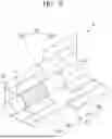
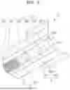
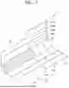

Sources:
- United States Patent and Trademark Office - verify current appl. status at the USPTO↗
Similar patent applications:
- » 20240099364
CELLULOSE ACETATE TOW, FILTER INCLUDING THE SAME, AND AEROSOL GENERATING ARTICLE INCLUDING THE FILTER - » 20240306697
TOBACCO MATERIAL, METHOD OF MANUFACTURING THE TOBACCO MATERIAL, FILTER INCLUDING THE TOBACCO MATERIAL, AND AEROSOL GENERATING ARTICLE INCLUDING THE FILTER - » 20260150880
FILTER WRAPPER FOR AEROSOL GENERATING ARTICLES AND FILTERS FOR AEROSOL GENERATING ARTICLES INCLUDING THE SAME - » 20230118486
AEROSOL GENERATING ARTICLE, THREAD FILTER, AND COOLING ARTICLE INCLUDING THREAD FILTER - » 20250098733
FLAVORED SHEET, FILTER, AND WRAPPER INCLUDING COOLING BLOCK, AND AEROSOL GENERATING ARTICLE INCLUDING THE SAME
Recent applications in this class:
- » 20240365854 2024-11-07
COOLING FILTER AND SMOKING ARTICLE INCLUDING THE SAME - » 20230172262 2023-06-08
FILTER FOR THE SORPTION OF COMPONENTS OF TOBACCO SMOKE WHICH ARE HARMFUL TO HEALTH - » 20210321667 2021-10-21
FILTER FOR SMOKING ARTICLE - » 20190191760 2019-06-27
Smoking article - » 20170325498 2017-11-16
System, apparatus and methods for a particulate filtration - » 20160073687 2016-03-17
Smoking article - » 20150305401 2015-10-29
Smoke filters for reducing components in a smoke stream - » 20140261502 2014-09-18
Smoke filters for reducing components in a smoke stream - » 20130032160 2013-02-07
Porous catalytic matrices for elimination of toxicants found in tobacco combustion products - » 20120160255 2012-06-28
Nanostructural filter for removing toxic compounds
Recent applications for this Assignee:
- » 20260150910 2026-06-04
AEROSOL GENERATION DEVICE - » 20260150896 2026-06-04
CARTRIDGE AND AEROSOL-GENERATING APPARATUS COMPRISING SAME - » 20260150880 2026-06-04
FILTER WRAPPER FOR AEROSOL GENERATING ARTICLES AND FILTERS FOR AEROSOL GENERATING ARTICLES INCLUDING THE SAME - » 20260144292 2026-05-28
AEROSOL-GENERATING DEVICE - » 20260137129 2026-05-21
AEROSOL GENERATING DEVICE AND METHOD FOR PERFORMING AUTHENTICATION OF DETACHABLE BATTERY IN AEROSOL GENERATING DEVICE - » 20260137112 2026-05-21
METHOD OF MANUFACTURING TOBACCO GRANULES - » 20260130439 2026-05-14
AEROSOL GENERATING DEVICE - » 20260130438 2026-05-14
AEROSOL GENERATING DEVICE - » 20260130437 2026-05-14
AEROSOL GENERATING DEVICE AND METHOD OF CONTROLLING THE SAME - » 20260130436 2026-05-14
AEROSOL GENERATION DEVICE AND OPERATION METHOD THEREFOR