CARTRIDGE AND AEROSOL-GENERATING APPARATUS COMPRISING SAME
US20260150896A1
2026-06-04
19/125,398
2024-08-05
Smart Summary: An aerosol-generating device has two main parts: a first container that holds a special material and a second container that makes aerosols from that material. The first container has an opening at the bottom, which is covered by a sealing member. This sealing member is held in place by small protrusions inside the first container. When the sealing member is removed, the aerosol-generating material can flow into the second container to create aerosols. This design helps to keep the materials separate until they are ready to be used. 🚀 TL;DR
Abstract:
An aerosol generating device according to an embodiment includes a first container storing an aerosol generating material and having an opening in a lower portion thereof, a second container connected to the lower portion of the first container and generating aerosols by receiving the aerosol generating material from the first container, and a sealing member arranged between the first container and the second container and covering the opening, wherein the first container further includes protrusions protruding from a lower inner side of a side wall and supporting the sealing member from above.
Inventors:
- Tae Hun KIM 18 🇰🇷 Gyeonggi-do, South Korea
- Hyung-Jin JUNG 60 🇰🇷 Seoul, South Korea
- Hun-Il LIM 75 🇰🇷 Seoul, South Korea
- Ju Eon PARK 14 🇰🇷 Gyeonggi-do, South Korea
- Youn Ji SHIN 22 🇰🇷 Seoul, South Korea
Assignee:
- KT&G CORPORATION 1,095 🇰🇷 Daejeon, South Korea
Applicant:
Interested in similar patents?
Get notified when new applications in this technology area are published.
Classification:
A24F40/42 » CPC main
Electrically operated smoking devices; Component parts thereof; Manufacture thereof; Maintenance or testing thereof; Charging means specially adapted therefor; Constructional details, e.g. connection of cartridges and battery parts Cartridges or containers for inhalable precursors
A24F40/46 » CPC further
Electrically operated smoking devices; Component parts thereof; Manufacture thereof; Maintenance or testing thereof; Charging means specially adapted therefor; Constructional details, e.g. connection of cartridges and battery parts Shape or structure of electric heating means
A24F40/57 » CPC further
Electrically operated smoking devices; Component parts thereof; Manufacture thereof; Maintenance or testing thereof; Charging means specially adapted therefor; Control or monitoring Temperature control
Description
TECHNICAL FIELD
One or more embodiments of the present disclosure relate to a cartridge and an aerosol generating apparatus including the same, and in particular, a cartridge having an improved structure so as to have an increased accommodation capacity of an aerosol generating material and an aerosol generating device including the same.
BACKGROUND ART
Recently, there has been increasing demand for alternative ways of overcoming the disadvantages of common cigarettes. For example, demand for a system for generating aerosols by heating a cigarette or an aerosol generating material by an aerosol generating device, not a method of combusting cigarette to generate aerosol, is increasing. Accordingly, research onto a heating-type aerosol generating device has been actively conducted.
A cartridge accommodating an aerosol generating material is installed in an aerosol generating device and may be used as a replaceable type. When the aerosol generating material accommodated in the cartridge is all consumed, a user may replace the cartridge with a new one to use the aerosol generating device. A cycle for the user to replace the cartridge is related to a capacity of the cartridge for accommodating the aerosol generating material.
DISCLOSURE OF INVENTION
Technical Problem
One or more embodiments provide a user with a cartridge configured to support a sealing member covering an opening of a first container from the above, through a protrusion structure.
One or more embodiments provide a user with an aerosol generating device providing a sufficient capacity of an aerosol generating material while providing stabilized sealing at an edge portion of the opening in the first container.
The problem to be solved by embodiments of the present disclosure is not limited to the problems described above, but includes problems that may be easily understood by those skilled in the art to which the present disclosure belongs from the present specification and attached drawings.
Solution to Problem
According to an embodiment, a cartridge includes a first container storing an aerosol generating material and having an opening in a lower portion thereof, a second container connected to the lower portion of the first container and generating aerosols by receiving the aerosol generating material from the first container, and a sealing member arranged between the first container and the second container and covering the opening, wherein the first container further includes protrusions protruding from a lower inner side of a side wall and supporting the sealing member from above.
According to an embodiment, an aerosol generating device includes a main body coupled to the cartridge so that aerosols generated by the cartridge flow therein and including an accommodating space accommodating an aerosol generating article, and a heater configured to heat the aerosol generating article accommodated in the main body.
Advantageous Effects of Invention
According to one or more embodiments, a cartridge having an improved structure and an increased capacity of an aerosol generating material, and an aerosol generating device including the cartridge may be provided to a user.
The effects according to embodiments of the present disclosure are not limited to the effects described above, and the effects not mentioned herein may be clearly understood by those who skilled in the art to which the embodiments belong from the specification and the accompanying drawings.
BRIEF DESCRIPTION OF DRAWINGS
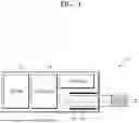
FIG. 1 is a diagram showing an example of an aerosol generating device including a cartridge according to an embodiment.
FIG. 2 is an exploded side view schematically showing an exterior of an aerosol generating device according to an embodiment.
FIG. 3 is a perspective view of a cartridge according to an embodiment.
FIG. 4 is an exploded perspective view of a cartridge according to an embodiment.
FIG. 5 is a side cross-sectional view of the cartridge according to an embodiment, taken along line A-A of FIG. 3.
FIG. 6 is a perspective cross-sectional view of the cartridge according to an embodiment, taken along line B-B of FIG. 3 and seen from a lower direction.
FIG. 7A is a perspective cross-sectional view of the cartridge according to an embodiment, taken along line C-C of FIG. 3 and seen from a +x-axis direction.
FIG. 7B is a perspective cross-sectional view of the cartridge according to an embodiment, taken along line C-C of FIG. 3 and seen from a −x-axis direction.
FIG. 8 is a cross-sectional view of the cartridge according to an embodiment, taken along line B-B of FIG. 3 and seen from an upper direction.
FIGS. 9A to 9C are conceptual diagrams schematically illustrating a contour of a side wall according to another embodiment.
FIG. 10 is a block diagram of an aerosol generating device 900 according to another embodiment.
BEST MODE FOR CARRYING OUT THE INVENTION
Mode for the Invention
All terms including descriptive or technical terms which are used herein should be construed as having meanings that are obvious to one of ordinary skill in the art. However, the terms may have different meanings according to an intention of one of ordinary skill in the art, precedent cases, or the appearance of new technologies. Also, some terms may be arbitrarily selected by the applicant. In this case, the meaning of the selected terms will be described in the detailed description. Thus, the terms used herein have to be defined based on the meaning of the terms together with the description throughout the specification.
It will be further understood that the terms “comprises” and/or “comprising,” when used in this specification, specify the presence of stated components, but do not preclude the presence or addition of one or more components. In addition, the terms such as “ . . . unit”, “module”, etc. provided herein indicates a unit performing at least one function or operation, and may be realized by hardware, software, or a combination of hardware and software.
As used herein, expressions such as “at least one of” when preceding a list of elements, modify the entire list of elements and do not modify the individual elements of the list. For example, the expression, “at least one of a, b, and c,” should be understood as including only a, only b, only c, both a and b, both a and c, both b and c, or all of a, b, and c.
In an embodiment, an aerosol generating device may be a device that generates aerosols by electrically heating a cigarette accommodated in an interior space thereof.
The aerosol generating device may include a heater. In an embodiment, the heater may be an electro-resistive heater. For example, the heater may include an electrically conductive track, and the heater may be heated when currents flow through the electrically conductive track.
The heater may include a tube-shaped heating element, a plate-shaped heating element, a needle-shaped heating element, or a rod-shaped heating element, and may heat the inside or outside of a cigarette according to the shape of a heating element.
A cigarette may include a tobacco rod and a filter rod. The tobacco rod may be formed of sheets, strands, and tiny bits cut from a tobacco sheet. Also, the tobacco rod may be surrounded by a heat conductive material. For example, the heat conductive material may be, but is not limited to, a metal foil such as aluminum foil.
The filter rod may include a cellulose acetate filter. The filter rod may include at least one segment. For example, the filter rod may include a first segment configured to cool aerosols, and a second segment configured to filter a certain component in aerosols.
In another embodiment, the aerosol generating device may be a device that generates aerosols by using a cartridge containing an aerosol generating material.
The aerosol generating device may include a cartridge that contains an aerosol generating material, and a main body that supports the cartridge. The cartridge may be detachably coupled to the main body, but is not limited thereto. The cartridge may be integrally formed or assembled with the main body, and may also be fixed to the main body so as not to be detached from the main body by a user. The cartridge may be mounted on the main body while accommodating an aerosol generating material therein. However, the present disclosure is not limited thereto, and an aerosol generating material may also be injected into the cartridge while the cartridge is coupled to the main body.
The cartridge may contain an aerosol generating material in any one of various states, such as a liquid state, a solid state, a gaseous state, a gel state, etc. The aerosol generating material may include a liquid composition. For example, the liquid composition may be a liquid including a tobacco-containing material including a volatile tobacco flavor component, or a liquid including a non-tobacco material.
The cartridge may be operated by an electrical signal or a wireless signal transmitted from the main body to perform a function of generating aerosols by converting the phase of an aerosol generating material inside the cartridge into a gaseous phase. The aerosols may refer to a gas in which vaporized particles generated from an aerosol generating material are mixed with air.
In another embodiment, the aerosol generating device may generate aerosols by heating a liquid composition, and generated aerosols may be delivered to a user through a cigarette. That is, the aerosols generated from the liquid composition may move along an airflow passage of the aerosol generating device, and the airflow passage may be configured to allow aerosols to be delivered to a user by passing through a cigarette.
In another embodiment, the aerosol generating device may be a device that generates aerosols from an aerosol generating material by using an ultrasonic vibration method. At this time, the ultrasonic vibration method may mean a method of generating aerosols by converting an aerosol generating material into aerosols with ultrasonic vibration generated by a vibrator.
The aerosol generating device may include a vibrator, and generate a short-period vibration through the vibrator to convert an aerosol generating material into aerosols. The vibration generated by the vibrator may be ultrasonic vibration, and the frequency band of the ultrasonic vibration may be in a frequency band of about 100 kHz to about 3.5 MHz, but is not limited thereto.
The aerosol generating device may further include a wick that absorbs an aerosol generating material. For example, the wick may be arranged to surround at least one area of the vibrator, or may be arranged to contact at least one area of the vibrator.
As a voltage (for example, an alternating voltage) is applied to the vibrator, heat and/or ultrasonic vibrations may be generated from the vibrator, and the heat and/or ultrasonic vibrations generated from the vibrator may be transmitted to the aerosol generating material absorbed in the wick. The aerosol generating material absorbed in the wick may be converted into a gaseous phase by heat and/or ultrasonic vibrations transmitted from the vibrator, and as a result, aerosols may be generated.
For example, the viscosity of the aerosol generating material absorbed in the wick may be lowered by the heat generated by the vibrator, and as the aerosol generating material having a lowered viscosity is granulated by the ultrasonic vibrations generated from the vibrator, aerosols may be generated, but is not limited thereto.
In another embodiment, the aerosol generating device is a device that generates aerosols by heating an aerosol generating article accommodated in the aerosol generating device in an induction heating method.
The aerosol generating device may include a susceptor and a coil. In an embodiment, the coil may apply a magnetic field to the susceptor. As power is supplied to the coil from the aerosol generating device, a magnetic field may be formed inside the coil. In an embodiment, the susceptor may be a magnetic body that generates heat by an external magnetic field. As the susceptor is positioned inside the coil and a magnetic field is applied to the susceptor, the susceptor generates heat to heat an aerosol generating article. In addition, optionally, the susceptor may be positioned within the aerosol generating article.
In another embodiment, the aerosol generating device may further include a cradle.
The aerosol generating device may configure a system together with a separate cradle. For example, the cradle may charge a battery of the aerosol generating device. Alternatively, the heater may be heated when the cradle and the aerosol generating device are coupled to each other.
Hereinafter, the present disclosure will now be described more fully with reference to the accompanying drawings, in which exemplary embodiments of the present disclosure are shown such that one of ordinary skill in the art may easily work the present disclosure. The present disclosure may be implemented in a form that may be implemented in the aerosol generating devices of the various embodiments described above or may be implemented in various different forms, and is not limited to the embodiments described herein.
Hereinafter, embodiments of the present disclosure will be described in detail with reference to the drawings.
FIG. 1 is a diagram showing an example of an aerosol generating device including a cartridge according to an embodiment.
Referring to FIG. 1, an aerosol generating device 10 may include a battery 13, a controller 14, a heater 121, and a cartridge 1. The aerosol generating device 10 of FIG. 1 may include a housing including an accommodation space 12 in which an aerosol generating article 11 is accommodated. The aerosol generating article 11 may be inserted into the aerosol generating device 10, and accordingly, the aerosol generating article 11 may be accommodated in the accommodation space 12 of the housing. Also, it is shown that the heater 121 is included in the aerosol generating device 10, but as necessary, the heater 121 may be omitted.
FIG. 1 shows components of the aerosol generating device 10, related with the embodiment. Therefore, universal components other than the components shown in FIG. 1 may be further included in the aerosol generating device 10.
FIG. 1 shows that the cartridge 1 and the heater 121 are arranged in parallel. However, an internal structure of the aerosol generating device 10 is not limited to the examples shown in FIG. 1. In other words, according to the design of the aerosol generating device 10, arrangements of the battery 13, the controller 14, the heater 121, and the cartridge 1 may be changed.
The heater 121 may heat the aerosol generating article 11. When the aerosol generating article 11 is inserted into the aerosol generating device 10, the aerosol generating device 10 may operate the heater 121 and/or the cartridge 1 to generate aerosols. The aerosols generated by the heater 121 and/or cartridge 1 may pass through the aerosol generating article 11 and may be transferred to a user.
The battery 13 supplies power used to operate the aerosol generating device 10. For example, the battery 13 may supply the power so that the heater 121 or the aerosol generating article 11 may be heated, and may supply the power that is necessary for the controller 14 to operate. In addition, the battery 13 may supply power for operating a display, a sensor, a motor, and the like installed in the aerosol generating device 10.
The controller 14 may control overall operations of the aerosol generating device 10. In detail, the controller 14 may control operations of components included in the aerosol generating device 10, other than the battery 13, the heater 121, and the cartridge 1. Also, the controller 14 may check the status of each component in the aerosol generating device 10 to determine whether the aerosol generating device 10 is in an operable state.
The controller 14 includes at least one processor. The processor may be implemented as an array of a plurality of logic gates, or as a combination of a universal microprocessor and a memory storing programs that may be executed in the microprocessor. It will be understood by one of ordinary skill in the art that the present disclosure may be implemented in other forms of hardware.
The heater 121 may be heated by the power supplied from the battery 13. For example, when the aerosol generating article 11 is inserted into the aerosol generating device 10, the heater 121 may be located outside the aerosol generating article 11. Therefore, the heater 121 that is heated may raise the temperature of the aerosol generating article 11.
The heater 121 may be an electrically resistant heater 121. For example, the heater 121 may include an electrically conductive track, and when the electric current flows on the electrically conductive track, the heater 121 may be heated. However, the heater 121 is not limited to the above example, and any type of heater may be used provided that the heater is heated to a desired temperature. Here, the desired temperature may be set in advance on the aerosol generating device 10, or may be set by the user.
In addition, in another example, the heater 121 may be an induction heating-type heater 121. In detail, the heater 121 may include an electrically conductive coil for heating the aerosol generating article 11 in an induction heating type, and the aerosol generating article 11 may include a susceptor that may be heated by the induction heating-type heater 121.
The aerosol generating article 11 may be a cigarette or other heatable materials. The aerosol generating article 11 may include tobacco leaves. However, the above description is an example of the aerosol generating article 11, and kinds of the aerosol generating article 11 are not limited thereto.
In FIG. 1, the heater 121 is arranged outside the aerosol generating article 11, but is not limited thereto. For example, the heater 121 may include a tube-shaped heating element 52, a plate-shaped heating element 52, a needle-shaped heating element 52, or a rod-shaped heating element 52, and inside or outside of the aerosol generating article 11 may be heated according to the shape of the heating element 52.
Also, there may be a plurality of heaters 121 in the aerosol generating device 10. Here, the plurality of heaters 121 may be arranged to be inserted into the aerosol generating article 11, or may be arranged on the outside of the aerosol generating article 11. Also, some of the plurality of heaters 121 may be arranged to be inserted into the aerosol generating article 11, and remaining heaters may be arranged on the outside of the aerosol generating article 11. Also, the shape of the heater 121 is not limited to the example shown in FIG. 1, and may be manufactured to have various shapes.
The cartridge 1 may generate aerosols by heating a liquid composition, and the generated aerosols may be transferred to the user after passing through the cigarette. In other words, the aerosols generated by the cartridge 1 may be moved along an air flow passage of the aerosol generating device 10, and the air flow passage may be configured so that the aerosols generated by the cartridge 1 may be transferred to the user after passing through the cigarette.
The cartridge 1 may accommodate the aerosol generating material. The aerosol generating material may be distinguished from the aerosol generating article 11. The aerosol generating material may be of a liquid composition type. The aerosol generating material may be a component of the cartridge 1, but is not limited thereto. For example, the aerosol generating material may be arranged on the outside of the cartridge 1. The aerosol generating material may be a component of the aerosol generating device 10.
For example, the aerosol generating material may be a liquid including a tobacco-containing material including a volatile tobacco flavor component, or a liquid including a non-tobacco material.
A liquid delivery unit may deliver the aerosol generating material of the liquid storage to the heating element 52. For example, the liquid delivery unit may be a wick 51 such as cotton fiber, ceramic fiber, glass fiber, or porous ceramic, but is not limited thereto.
The heating element 52 may be an element for heating the aerosol generating material delivered by the liquid delivery unit. For example, the heating element 52 may include a metal heating wire, a metal hot plate, a ceramic heater 121, etc., but is not limited thereto. In addition, the heating element 52 may include a conductive filament such as nichrome wire and may be wound around the liquid delivery element. The heating element 52 may be heated by a current supply and may transfer the heat to the aerosol generating material coming into contact with the heating element 52 to heat the aerosol generating material. As a result, the aerosols may be generated from the aerosol generating material.
FIG. 2 is an exploded side view schematically showing the exterior of an aerosol generating device according to an embodiment.
Referring to FIG. 2, the aerosol generating device 10 according to an embodiment may include a cover 15, a main body 16, a button 17, and the cartridge 1. Here, the aerosol generating device 10 and the cartridge 1 may be the same as the aerosol generating device 10 and the cartridge 1 described above with reference to FIG. 1.
The cover 15 is coupled to one end portion of the main body 16 so as to form an exterior of the aerosol generating device 10 along with the main body 16 and the cover 15. An insertion space into which the aerosol generating article 11 may be inserted may be formed in the upper surface of the cover 15 coupled to the main body 16.
The main body 16 may form a portion of the exterior of the aerosol generating device 10, and accommodate and protect the components of the aerosol generating device 10. For example, the battery 13, the controller 14, and/or the heater 121 may be accommodated in the main body 16, but are not limited thereto.
The main body 16 and the cover 15 may be formed of a plastic material that rarely transfers the heat, or a metal material coated with a heat blocking material. The main body 16 and the cover 15 may be manufactured by, for example, an injection molding method, a 3D printing method, or in a manner of assembling small-sized components manufactured through injection molding.
The components of the aerosol generating device 10 are not limited to the above-described embodiment, and the aerosol generating device 10 according to another embodiment may not include the cover 15.
The cover 15 may be released from the main body 16, and separated from the main body 16. For example, the cover 15 may be separated from the main body 16 in a z-axis direction. When the cover 15 separates from the main body 16, an upper portion of the main body 16, the button 17, and the cartridge 1 may be exposed to outside.
The button 17 may be arranged so that at least a portion thereof is exposed out of the main body 16, and according to a user's input, the button 17 may release a fastening relation between the main body 16 and the cartridge 1. For example, when the user's input is applied to the button 17, the cartridge 1 may be detached from the main body 16.
The cartridge 1 stores the aerosol generating material and may be detachably coupled to one end portion of the main body 16.
According to an embodiment, the cartridge 1 may be coupled to the main body 16 including the controller 14 and/or the battery 13, and may be applied as a component of the aerosol generating device 10. For example, the heating element 52 (not shown) included in the cartridge 1 may be electrically connected to the main body 16 to receive the power supply from the battery 13, and the power supply may be controlled by the controller 14.
That is, in the aerosol generating device 10 including the cartridge 1, the power is supplied to the heating element 52 and controlled, and thus, the liquid or gel-phase aerosol generating material stored in the cartridge 1 may generate aerosols. The aerosols generated from the cartridge 1 may flow into the main body 16.
The aerosol generating device 10 including the cartridge 1 may heat the aerosol generating material stored in the cartridge 1 to generate aerosols, and moreover, may heat the aerosol generating article 11 inserted therein to generate aerosols. Accordingly, the aerosol generating device 10 of a hybrid type may be implemented.
FIG. 2 depicts the behavior of the cartridge 1 approaching from the side of the main body 16 and being coupled to the main body 16, but the coupling manner between the cartridge 1 and the main body 16 is not limited thereto. For example, the cartridge 1 may be coupled to the main body 16 after approaching the main body 16 in a −z direction from a position spaced apart from the main body 16 in a z-direction, like the cover 15.
According to an embodiment, the cartridge 1 may be inserted into and detached from the aerosol generating device 10. When the aerosol generating material stored in the cartridge 1 is all consumed up, the aerosol generating material may be recharged, or the cartridge 1 may be replaced with a new one storing the aerosol generating material.
Referring back to FIGS. 1 and 2, the controller 14 according to the embodiment may receive information as to a remaining amount of the aerosol generating material. The cartridge 1 may transmit to the controller 14 information about the remaining amount of the aerosol generating material. The aerosol generating device 10 may control whether to heat the aerosol generating article 11 by controlling the heater 121 according to the remaining amount of the aerosol generating material 2. The controller 14 may control whether to heat the aerosol generating article 11 by controlling the heater 121 according to the remaining amount of the aerosol generating material. For example, the controller 14 may not heat the aerosol generating article 11 when the remaining amount of the aerosol generating is less than or equal to a certain amount.
In addition, a consuming pattern of the aerosol generating article 11 may be related to a distribution structure of the aerosol generating article 11 according to certain standards. The aerosol generating article 11 may be distributed in units of certain numbers. The aerosol generating article 11 may be distributed in certain bundle units. For example, the aerosol generating article 11 may be distributed in units of 20. The distribution of the aerosol generating article 11 may denote that the user purchases the aerosol generating article 11 from a retail store. For example, the user may generally purchase the aerosol generating articles 11 in units of 20. However, the general distribution structure and purchasing units of the aerosol generating article 11 are not limited to the above example. In addition, the aerosol generating material may be supplied to the user through a distribution structure similar to that of the aerosol generating article 11.
The amount of aerosol generating material 2 that the cartridge 1 according to the embodiment is capable of accommodating may be related to a user's pattern of consuming the aerosol generating article 11. When the amount of the aerosol generating material that the cartridge 1 is capable of accommodating is adjusted according to the consuming pattern of the aerosol generating article 11, the convenience in use of the aerosol generating device 10 may be improved. When a size of a space 61 in the cartridge 1, which may accommodate the aerosol generating material, is designed to be suitable for the consuming pattern of the aerosol generating article 11, the convenience in use of the aerosol generating device 10 may be improved.
The aerosol generating device 10 according to an embodiment may generate aerosols by simultaneously consuming the aerosol generating article 11 and the aerosol generating material 2. The aerosol generating device 10 consuming the aerosol generating article 11 may denote that the heater 121 heats the aerosol generating article 11. While the aerosol generating device 10 generates aerosols by consuming one unit of aerosol generating article 11, the cartridge 1 may generate the aerosols by consuming a certain amount of aerosol generating material.
A standard about the amount of aerosol generating material consumed in the cartridge 1 while the aerosol generating device 10 consumes one unit of aerosol generating article 11 may be set in advance.
A certain standard about the amount of aerosol generating material consumed in the cartridge 1 may be a standardized value after analyzing the user's consumption pattern with respect to the aerosol generating device 10. For example, while the aerosol generating device consumes one aerosol generating article 11, the aerosol generating material 2 consumed by the cartridge 1 may be standardized as about 0.06 ml. However, the quantitative relationship between the aerosol generating article 11 and the aerosol generating material in the aerosol generating device 10 is not limited to the above description.
The amount of aerosol generating material 2 that may be accommodated by the cartridge 1 according to the embodiment may be related to the amount of the aerosol generating material consumed by the cartridge 1 when the aerosol generating device 10 consumes a specific distribution unit or transaction unit of the aerosol generating material.
The aerosol generating article 11 may be distributed in units of certain numbers. The aerosol generating article 11 may be distributed in certain bundle units. For example, the aerosol generating article 11 may be distributed in units of 20. The distribution of the aerosol generating article 11 may denote that the user purchases the aerosol generating article 11 from a retail store. For example, the user may generally purchase the aerosol generating articles 11 in units of 20. However, the distribution unit or transaction unit of the aerosol generating material 2 is not limited to the above description.
The amount of the aerosol generating material 2 that may be accommodated by the cartridge 1 according to the embodiment may be in proportional to the number of aerosol generating articles 11 that may be heated without replacing the cartridge 1. The number of aerosol generating articles 11 that may be heated without replacing the cartridge 1 may denote the number of aerosol generating articles 11 that may be heated by using one cartridge 1.
The amount of aerosol generating material that may be accommodated by one cartridge 1 may be integer times of the amount of aerosol generating material consumed by the cartridge 1 while the aerosol generating device 10 consumes twenty aerosol generating articles 11.
For example, when one cartridge 1 consumes the aerosol generating material of about 0.06 ml while the aerosol generating device 10 consumes one aerosol generating article 11, the cartridge 1 may consume the aerosol generating material of about 1.2 ml while the aerosol generating device 10 consumes twenty aerosol generating articles 11.
In another example, when the cartridge 1 consumes the aerosol generating material 2 of about 0.06 ml while the aerosol generating device 10 consumes one aerosol generating article 11, the cartridge 1 may consume the aerosol generating material of about 2.4 ml while the aerosol generating device 10 consumes forty aerosol generating articles 11. However, the quantitative relationship between the consumptions of the aerosol generating article 11 and the aerosol generating material in the aerosol generating device 10 is not limited to the above description.
When the amount of the aerosol generating material that may be accommodated by the cartridge 1 is integer times of the transaction unit of the aerosol generating articles 11, the replacement cycle of the cartridge 1 may coincide with the transaction cycle of the aerosol generating material. When the replacement cycle of the cartridge 1 of the user coincides with the transaction cycle of the aerosol generating material, the convenience in use of the aerosol generating device 10 may be improved. However, the transaction unit of the aerosol generating article 11 and the amount of the aerosol generating material 2 accommodated by the cartridge 1 are not limited to the above description.
The amount of the aerosol generating material accommodated in the cartridge 1 may be set to be an amount obtained by adding 10% more to the standard consumption amount of the aerosol generating material considering an error caused according to the personal usage pattern of the user. For example, the cartridge 1 may accommodate the aerosol generating material of about 1.32 ml. For example, the cartridge 1 may accommodate the aerosol generating material of about 2.64 ml. For example, the cartridge 1 may accommodate the aerosol generating material of 1.5 ml to 4 ml. For example, the cartridge 1 may accommodate the aerosol generating material of 2.4 ml to 2.8 ml. For example, the aerosol generating device 10 may heat the aerosol generating articles 11 by an integer multiple of 22 without replacing the cartridge 1. For example, the aerosol generating device 10 may heat the aerosol generating articles 11 by an integer multiple of 22 without replacing the cartridge 1. For example, the aerosol generating device 10 may heat 42 to 46 aerosol generating articles 11 without replacing the cartridge 1.
The amount of the aerosol generating material accommodated by the cartridge 1 may be set to be an amount obtained by adding 5% or 15% more to the standard consumption amount of the aerosol generating material considering an error caused according to the personal usage pattern of the user. For example, the aerosol generating device 10 may heat the aerosol generating articles 11 by an integer multiple of 21 without replacing the cartridge 1. For example, the aerosol generating device 10 may heat the aerosol generating articles 11 by an integer multiple of 23 without replacing the cartridge 1.
FIG. 3 is a perspective view of a cartridge according to an embodiment. FIG. 4 is an exploded perspective view of a cartridge according to an embodiment.
FIG. 5 is a side cross-sectional view of the cartridge according to an embodiment, taken along line A-A of FIG. 3. FIG. 6 is a perspective cross-sectional view of the cartridge according to an embodiment, taken along line B-B of FIG. 3 and seen from a lower direction.
Referring to FIGS. 3 and 4, the cartridge 1 according to an embodiment may include a first container 3, a second container 6, and the heating element 52.
The first container 3 may store the aerosol generating material and include an opening 30 in the lower portion thereof. The opening 30 of the first container 3 may be a space 61 defined by lower end portions of inner walls of the first container 3.
The second container 6 may accommodate the heating element 52. The second container 6 may be connected to the lower portion of the first container 3. The second container 6 may extend along a direction in which the first container 3 extends.
The heating element 52 may heat the aerosol generating material. The heating element 52 may generate aerosols by heating the aerosol generating material. The heating element 52 may heat the aerosol generating material transferred to the second container 6 through the opening 30 in the lower portion of the first container 3, so as to generate aerosols. However, the aerosol generating material that may be heated by the heating element 52 is not limited to that transferred to the second container 6 from the first container 3.
The cartridge 1 according to the embodiment may include a frame 5 and a wick 51. The frame 5 may be inserted into the space 61 in the second container 6 to be coupled to the second container 6. The wick 51 may absorb the aerosol generating material. The wick 51 may fix the position of the aerosol generating material so that the heating element 52 may sufficiently heat the aerosol generating material. The wick 51 may be accommodated in a wick coupling recess 53 included in the frame 5.
The aerosol generating material that is absorbed by the wick 51 and heated by the heating element may become the aerosols and may be discharged through a chamber discharge port 55 of the frame 5. The chamber discharge port 55 may be connected to a cartridge discharge port 62 of the second container 6. The cartridge discharge port 62 may discharge the aerosols to the outside of the cartridge 1.
The first container 3 according to the embodiment may include an upper cover 34 on the upper portion thereof. The upper cover 34 may be connected to a side wall 33. The upper cover 34 may be attached to the side wall 33 via a UV sealing or an ultrasonic process. However, the upper cover 34 may be integrally formed with the side wall 33.
The upper cover 34 may include an inflow passage 32 through which air outside the cartridge 1 flows in. The inflow passage 32 may transfer the air on the outside of the cartridge 1 into the frame 5 through a cartridge flow path 54 of the frame 5.
The cartridge 1 according to the embodiment may include a sealing member 4. The sealing member 4 may prevent leakage of the aerosol generating material. The sealing member 4 may be coupled to at least a portion of the first container 3 so that the aerosol generating material stored in the first container 3 may be prevented from leaking out of the cartridge 1.
The sealing member 4 may include an inflow hole 41 and a connection hole 42. A plurality of inflow holes 41 may be formed in the position corresponding to the end portions of the wick 51. The inflow hole 41 may transfer the aerosol generating material in the first container 3 to the second container 6. The connection hole 42 may transfer the external air flowing in through the inflow passage 32 to the second container 6.
The sealing member 4 may be arranged between the first container 3 and the second container 6. The sealing member 4 may cover (15) the opening 30 of the first container 3. The sealing member 4 may prevent leakage of the aerosol generating material 2 to the outside of the first container 3. The leakage of the aerosol generating material to the outside of the first container 3 may denote that the aerosol generating material in the first container 3 is moved to the space 61 other than the inflow hole 41 of the sealing member 4 or to the outside of the cartridge 1. The sealing member 4 may cover (15) an edge portion of the opening 30 of the first container 3.
The sealing member 4 may be formed of a material that may be closely coupled to a portion of the first container 3. The sealing member 4 may include an elastic material. For example, the sealing member 4 may be formed of an elastic material such as rubber or silicone, but is not limited thereto.
The sealing member 4 is coupled closely to at least a portion of the opening 30 through which the space 61 in the first container 3 may be exposed, to prevent the leakage of the aerosol generating material. Here, the close coupling may denote that the sealing member 4 is firmly coupled to the first container 3 so that a gap through which the aerosol generating material leaks may not be formed between the first container 3 and another component.
The sealing member 4 may be coupled to coupling portions of the first container 3 and the second container 6. When the sealing member 4 is not appropriately fixed to the coupling portions of the first container 3 and the second container 6, the aerosol generating material may leak from the first container 3. A degree of freedom of the flow of the sealing member 4 may be appropriately restricted so that the sealing member 4 may be appropriately fixed. The degree of freedom of flow of the sealing member 4 may denote ‘degree and/or amount of deformation’ when the sealing member 4 is elastically pressed between the first container 3 and the second container 6 in order for the sealing member 4 to sufficiently seal the space between the first container 3 and the second container 6. The degree of freedom of flow of the sealing member 4 may denote ‘degree and/or amount of deformation’ of the sealing member 4 that is elastically pressed and deformed in a direction of gravity application. The degree of freedom of flow of the sealing member 4 may denote ‘degree and/or amount of deformation’ of the sealing member 4 of which at least a portion is elastically pressed and deformed in a direction opposite to the force. The direction opposite to the force may be caused due to a virtual inertial force, but is not limited thereto.
The sealing member 4 may be fixed between the frame 5 and the first container 3. The sealing member 4 may be supported by the frame 5 from the below. A contact area between the sealing member 4 and the frame 5 may be greater than that between the sealing member 4 and the first container 3. A degree of freedom in flow of the sealing member 4 in the lower direction may not be large. When there is no configuration supporting the sealing member 4 from above, the degree of freedom in flow of the sealing member 4 in the upper direction may be greater than that in the lower direction. When the sealing member 4 moves upward, the sealing member 4 may not cover (15) the edge side of the opening 30 in the first container 3. When the edge of the opening 30 in the first container 3 is not covered (15) by the sealing member 4, the aerosol generating material may leak out of the cartridge 1.
Referring to FIGS. 5 and 6, the first container 3 according to the embodiment may include protrusions 31. The protrusion 31 may protrude from the lower inner side of the side wall 33 of the first container 3. The protrusion 31 may support the sealing member 4 from the above. An end portion of the protrusion 31 may come into contact with the upper surface of the sealing member 4.
The protrusion 31 may restrict the degree of freedom in flow of the sealing member 4 in the upper direction. The protrusion 31 may prevent at least a portion of the sealing member 4 from being deformed in the upper direction. The protrusion 31 may assist the sealing member 4 to be maintained at an appropriate position between the first container 3 and the second container 6.
Also, the protrusion 31 may maintain a distance between the sealing member 4 and the first container 3. The protrusion 31 may assist the sealing member 4 to cover (15) the opening 30 of the first container 3. The protrusion 31 may assist the sealing member 4 to prevent the leakage of the aerosol generating material accommodated in the first container 3 to the outside of the cartridge 1. There may be a plurality of protrusions 31. The protrusions 31 may be arranged along the boundary of the sealing member 4. However, functions and roles of the protrusions 31 are not limited to the above description.
FIG. 7A is a perspective cross-sectional view of the cartridge according to an embodiment, taken along line C-C of FIG. 3 and seen from a +x direction. FIG. 7B is a perspective cross-sectional view of the cartridge according to an embodiment, taken along line C-C of FIG. 3 and seen from a −x direction.
Referring to FIGS. 7A and 7B, components of the cartridge 1 according to the embodiment may have certain heights in a +z-direction.
A height h1 of the first container 3 may be a distance from a coupling point between the first container 3 and the second container 6 to the upper cover 34 of the first container 3.
A height h2 of the second container 6 may be a distance from the coupling point between the first container 3 and the second container 6 to the lower end of the second container 6.
A height h3 of the protrusion 31 may denote a length of the protrusion 31 that protrudes from the inner side surface of the first container 3 in a direction parallel to the z-axis direction. The height h3 of the protrusion 31 may denote a length of the protrusion 31 measured from the inner side surface of the first container 3 in a direction parallel to the z-axis direction.
When the space 61 occupied by the protrusion 31 according to the embodiment in the first container 3 is not large, the amount of aerosol generating material that may be accommodated in the first container 3 may increase.
The height h3 of the protrusion 31 in the upper direction may be 0.5% to 20% of the height h1 of the first container 3 in the upper direction. The height h3 of the protrusion 31 in the upper direction may be 0.7% to 15% of the height h1 of the first container 3 in the upper direction. The height h3 of the protrusion 31 in the upper direction may be 1% to 10% of the height h1 of the first container 3 in the upper direction. When the height h3 of the protrusion 31 in the upper direction is relatively less than the height h1 of the first container 3 in the upper direction, the amount of aerosol generating material that may be accommodated in the first container 3 may increase. However, a ratio between the heights of the protrusion 31 and the first container 3 is not limited to the above description.
The ‘upper direction’ may denote a direction in which the cartridge 1 lengthily extends, that is, z-axis direction.
The second container 6 according to the embodiment may include a plurality of other components than the aerosol generating material. The ratio of a volume occupied by the aerosol generating material with respect to a total volume in the cartridge 1 may be the largest.
When a volume ratio of the first container 3 is greater than a volume ratio of the second container 6, the amount of the aerosol generating material that may be accommodated by the cartridge 1 may increase. The height h2 of the second container 6 in the upper direction may be 20% to 40% of the height h1 of the first container 3 in the upper direction. The height h2 of the second container 6 in the upper direction may be 15% to 35% of the height h1 of the first container 3 in the upper direction. The height h2 of the second container 6 in the upper direction may be 10% to 30% of the height h1 of the first container 3 in the upper direction. When the height h1 of the first container 3 is relatively greater as compared with the height h2 of the second container 6, the amount of the aerosol generating material that may be accommodated by the cartridge 1 may be increased.
FIG. 8 is a cross-sectional view of the cartridge according to an embodiment, taken along line B-B of FIG. 3 and seen from the upper direction.
Referring to FIGS. 3 and 8, the first container 3 according to the embodiment may have a transverse width w1 and a longitudinal width w2. The transverse width w1 may be a maximum distance formed by an outer surface of the side wall 33 in a y-axis direction. The longitudinal width w2 may be a maximum distance formed by the outer surface of the side wall 33 in the x-axis direction.
An area formed by the inner surface of the side wall 33 of the first container 3 according to the embodiment may be defined as an area of a closed loop formed by the inner surface of the side wall 33 of the first container 3 in the cross-section of the first container 3 taken along a plane parallel to the z-axis. As the area formed by the inner surface of the side wall 33 of the first container 3 increases, the amount of the aerosol generating material that may be accommodated in the first container 3 may be increased. In the cross-section of the first container 3 taken along a direction perpendicular to the height direction, the area of the inside of the side wall 33 may be 68 mm2 to 80 mm2. However, the area in the side wall 33 is not limited to the above description.
The side wall 33 of the first container 3 may have a certain thickness w3. When an outer surface of the side wall 33 of the first container 3 has a consistent area, the area formed by the inner surface of the side wall 33 of the first container 3 may be increased as the thickness w3 of the side wall 33 is reduced. As the thickness w3 of the side wall 33 is reduced, the amount of the aerosol generating material that may be accommodated in the first container 3 may be increased. As the thickness w3 of the side wall 33 is reduced as compared with the transverse width w1 and the longitudinal width w2, the amount of the aerosol generating material that may be accommodated in the first container 3 may be increased. The thickness w3 of the side wall 33 may be 2% to 7% of the transverse width w1. The thickness w3 of the side wall 33 may be 3% to 10% of the longitudinal width w2. However, the thickness w3 of the side wall 33 is not limited to the above description.
FIGS. 9A to 9C are conceptual diagrams schematically illustrating a contour of a side wall according to another embodiment.
Referring to FIGS. 3, 8, and 9A to 9C, the side wall 33 included in the first container 1 may have external contours 330a, 330b, and 330c. The external contours 330a, 330b, and 330c may respectively include straight line portions 331a, 331b, and 331c and curved portions 332a, 332b, and 332c. The side wall 33 of the first container 3 may have the external contours 330a, 330b, and 330c respectively including the straight line portions 331a, 331b, and 331c and the curved portions 332a, 332b, and 332c in the direction perpendicular to the height direction. The height direction may denote a direction in which the first container extends, that is, the z-axis direction.
Opposite ends of each of the straight line portions 331a, 331b, and 331c according to the embodiment may be connected to opposite ends of each of the curved portions 332a, 332b, and 332c.
When the first container 3 is taken into a cross-section perpendicular to the height direction, the shape formed by the external contour 330a may be a substantially semicircular shape. The curved portion 332a may have an arc shape having a 90-degree central angle. Here, when a curved degree of at least a portion of the curved portion 332a increases, the external contour 330a may be deformed in an expanding direction.
Referring to FIG. 9B, when the external contour 330b of the curved portion 332b according to the embodiment expands, the area inside the side wall 33 may increase. When the area inside the side wall 33 increases, the amount of the aerosol generating material that may be accommodated in the first container 3 may be increased. When the curved portion 332b is deformed to be convex based on the straight line portion, the amount of the aerosol generating material that may be accommodated in the first container 3 may be increased. When the curved portion 332b is deformed, a distance from the straight line portion 331b and an upper end of the curved portion 332b may not be changed, but is not limited thereto.
The cartridge 1 according to the embodiment may maintain a certain curve on the curved portion 332 in order to secure the user's convenience in use. When the curved portion 332 has a certain curve shape, the cartridge may not slip from the hand of the user. The external contour 330 of the cartridge 1 may have a shape between a semicircle and a rectangle, so as to maintain the balance between the user's convenience in use and the capacity of the aerosol generating material. The curved portion 332b may be formed to have a plurality of radii of curvature. The capacity of the aerosol generating material may denote a total amount of the aerosol generating material that may be accommodated by the cartridge 1.
Referring to FIG. 9C, the curved portion 332c of the external contour 330c may have a trapezoidal shape having a cross-section of which apexes are curved. The curved portion 332c may have a rectangular shape having an upper side of which the apexes are round. When the curved portion 332c is formed close to the rectangular shape while maintaining a minimum curved degree, the balance between the user's convenience in use and the capacity of the aerosol generating material may be appropriately maintained.
FIG. 10 is a block diagram of an aerosol generating device 900 according to another embodiment.
The aerosol generating device 900 may include a controller 910, a sensing unit 980, an output unit 930, a battery 940, a heater 950, a user input unit 960, a memory 970, and a communication unit 980. However, an internal structure of the aerosol generating device 900 is not limited to the examples shown in FIG. 10. That is, according to the design of the aerosol generating device 900, it will be understood by one of ordinary skill in the art that some of the components shown in FIG. 10 may be omitted or new components may be added.
The sensing unit 980 may sense a state of the aerosol generating device 900 and a state around the aerosol generating device 900, and transmit sensed information to the controller 910. Based on the sensed information, the controller 910 may control the aerosol generating device 900 to perform various functions, such as controlling an operation of the heater 950, limiting smoking, determining whether an aerosol generating article (e.g., a cigarette, a cartridge, etc.) is inserted, displaying a notification, etc.
The sensing unit 980 may include at least one of a temperature sensor 922, an insertion detection sensor 924, and a puff sensor 926, but is not limited thereto.
The temperature sensor 922 may detect a temperature at which the heater 950 (or an aerosol generating material) is heated. The aerosol generating device 900 may include a separate temperature sensor for detecting the temperature of the heater 950, or the heater 950 may serve as a temperature sensor. Alternatively, the temperature sensor 922 may also be arranged around the battery 940 to monitor the temperature of the battery 940.
The insertion detection sensor 924 may detect insertion and/or removal of an aerosol generating article. For example, the insertion detection sensor 924 may include at least one of a film sensor, a pressure sensor, an optical sensor, a resistive sensor, a capacitive sensor, an inductive sensor, and an infrared sensor, and may detect a signal change according to the insertion and/or removal of an aerosol generating article.
The puff sensor 926 may detect a user's puff on the basis of various physical changes in an airflow passage or an airflow channel. For example, the puff sensor 926 may detect a user's puff on the basis of any one of a temperature change, a flow change, a voltage change, and a pressure change.
The sensing unit 980 may further include, in addition to the above sensors 922 to 926, at least one of a temperature/humidity sensor, a barometric pressure sensor, a magnetic sensor, an acceleration sensor, a gyroscope sensor, a location sensor (e.g., a global positioning system (GPS)), a proximity sensor, and a red-green-blue (RGB) sensor (illuminance sensor). Because a function of each of sensors may be intuitively inferred by one of ordinary skill in the art from the name of the sensor, a detailed description thereof may be omitted.
The output unit 930 may output information on a state of the aerosol generating device 900 and provide the information to a user. The output unit 930 may include at least one of a display unit 932, a haptic unit 934, and a sound output unit 936, but is not limited thereto. When the display unit 932 d and a touch pad form a layered structure to form a touch screen, the display unit 932 may also be used as an input device in addition to an output device.
The display unit 932 may visually provide information about the aerosol generating device 900 to the user. For example, the information about the aerosol generating device 900 may mean various pieces of information, such as a charging/discharging state of the battery 940 of the aerosol generating device 900, a preheating state of the heater 950, an insertion/removal state of an aerosol generating article, or a state in which the use of the aerosol generating device 900 is restricted (e.g., sensing of an abnormal object), etc., and the display unit 932 may output the information to the outside. The display unit 932 may be, for example, a liquid crystal display panel (LCD), an organic light-emitting diode (OLED) display panel, etc. In addition, the display unit 932 may be in the form of a light-emitting diode (LED) light-emitting device.
The haptic unit 934 may tactilely provide information about the aerosol generating device 900 to the user by converting an electrical signal into a mechanical stimulus or an electrical stimulus. For example, the haptic unit 934 may include a motor, a piezoelectric element, or an electrical stimulation device.
The sound output unit 936 may audibly provide information about the aerosol generating device 900 to the user. For example, the sound output unit 936 may convert an electrical signal into a sound signal and output the same to the outside.
The battery 940 may supply power used to operate the aerosol generating device 900. The battery 940 may supply power such that the heater 950 may be heated. In addition, the battery 940 may supply power required for operations of other components (e.g., the sensing unit 980, the output unit 930, the user input unit 960, the memory 970, and the communication unit 980) in the aerosol generating device 900. The battery 940 may be a rechargeable battery or a disposable battery. For example, the battery 940 may be a lithium polymer (LiPoly) battery, but is not limited thereto.
The heater 950 may receive power from the battery 940 to heat an aerosol generating material. Although not illustrated in FIG. 10, the aerosol generating device 900 may further include a power conversion circuit (e.g., a direct current (DC)/DC converter) that converts power of the battery 940 and supplies the same to the heater 950. In addition, when the aerosol generating device 900 generates aerosols in an induction heating method, the aerosol generating device 900 may further include a DC/alternating current (AC) converter that converts DC power of the battery 940 into AC power.
The controller 910, the sensing unit 980, the output unit 930, the user input unit 960, the memory 970, and the communication unit 980 may each receive power from the battery 940 to perform a function. Although not illustrated in FIG. 10, the aerosol generating device 900 may further include a power conversion circuit that converts power of the battery 940 to supply the power to respective components, for example, a low dropout (LDO) circuit, or a voltage regulator circuit.
In an embodiment, the heater 950 may be formed of any suitable electrically resistive material. For example, the suitable electrically resistive material may be a metal or a metal alloy including titanium, zirconium, tantalum, platinum, nickel, cobalt, chromium, hafnium, niobium, molybdenum, tungsten, tin, gallium, manganese, iron, copper, stainless steel, nichrome, etc., but is not limited thereto. In addition, the heater 950 may be implemented by a metal wire, a metal plate on which an electrically conductive track is arranged, a ceramic heating element, etc., but is not limited thereto.
In another embodiment, the heater 950 may be a heater of an induction heating type. For example, the heater 950 may include a susceptor that heats an aerosol generating material by generating heat through a magnetic field applied by a coil.
The user input unit 960 may receive information input from the user or may output information to the user. For example, the user input unit 960 may include a key pad, a dome switch, a touch pad (a contact capacitive method, a pressure resistance film method, an infrared sensing method, a surface ultrasonic conduction method, an integral tension measurement method, a piezo effect method, etc.), a jog wheel, a jog switch, etc., but is not limited thereto. In addition, although not illustrated in FIG. 10, the aerosol generating device 900 may further include a connection interface, such as a universal serial bus (USB) interface, and may be connected to other external devices through the connection interface, such as the USB interface, to transmit and receive information, or to charge the battery 940.
The memory 970 is a hardware component that stores various types of data processed in the aerosol generating device 900, and may store data processed and data to be processed by the controller 910. The memory 970 may include at least one type of storage medium from among a flash memory type, a hard disk type, a multimedia card micro type memory, a card-type memory (for example, secure digital (SD) or extreme digital (XD) memory, etc.), random access memory (RAM), static random access memory (SRAM), read-only memory (ROM), electrically erasable programmable read-only memory (EEPROM), programmable read-only memory (PROM), a magnetic memory, a magnetic disk, and an optical disk. The memory 970 may store an operation time of the aerosol generating device 900, the maximum number of puffs, the current number of puffs, at least one temperature profile, data on a user's smoking pattern, etc.
The communication unit 980 may include at least one component for communication with another electronic device. For example, the communication unit 980 may include a short-range wireless communication unit 1082 and a wireless communication unit 1084.
The short-range wireless communicator 982 may include, but is not limited to, a Bluetooth communicator, a Bluetooth low energy (BLE) communicator, a near field communication unit, a WLAN (Wi-Fi) communicator, a ZigBee communicator, an infrared-ray data association (IrDA) communicator, a Wi-Fi direct (WFD) communicator, an ultra wideband (UWB) communicator, an Ant+ communicator, etc.
The wireless communication unit 1084 may include a cellular network communication unit, an Internet communication unit, a computer network (e.g., local area network (LAN) or wide area network (WAN)) communication unit, etc., but is not limited thereto. The wireless communication unit 1084 may also identify and authenticate the aerosol generating device 900 within a communication network by using subscriber information (e.g., International Mobile Subscriber Identifier (IMSI)).
The controller 910 may control the overall operation of the aerosol generating device 900. In an embodiment, the controller 910 may include at least one processor. The processor may be implemented as an array of a plurality of logic gates, or as a combination of a universal microprocessor and a memory storing programs that may be executed in the microprocessor. It will be understood by one of ordinary skill in the art that the present disclosure may be implemented in other forms of hardware.
The controller 910 may control the temperature of the heater 950 by controlling supply of power of the battery 940 to the heater 950. For example, the controller 910 may control power supply by controlling switching of a switching element between the battery 940 and the heater 950. In another example, a direct heating circuit may also control power supply to the heater 950 according to a control command of the controller 910.
The controller 910 may analyze a result sensed by the sensing unit 980 and control subsequent processes to be performed. For example, the controller 910 may control power supplied to the heater 950 to start or end an operation of the heater 950 on the basis of a result sensed by the sensing unit 980. As another example, the controller 910 may control, based on a result sensed by the sensing unit 980, an amount of power supplied to the heater 950 and the time the power is supplied, such that the heater 950 may be heated to a certain temperature or maintained at an appropriate temperature.
The controller 910 may control the output unit 930 on the basis of a result sensed by the sensing unit 980. For example, when the number of puffs counted through the puff sensor 926 reaches a preset number, the controller 910 may notify the user that the aerosol generating device 900 will soon be terminated through at least one of the display unit 932, the haptic unit 934, and the sound output unit 936.
An embodiment of the disclosure may be embodied in a storage medium including instruction codes executable by a computer or processor such as a program module executed by the computer. The computer-readable storage medium may be any available medium that may be accessed by a computer, and includes volatile and non-volatile media and removable and non-removable media. Also, the computer-readable storage medium may include both a computer storage medium and a communication medium. The computer storage medium may include volatile and non-volatile media and removable and non-removable media that are implemented using any method or technology for storing information, such as computer-readable instructions, a data structure, a program module, or other types of data. The communication medium typically includes computer-readable instructions, a data structure, a program module, or other data of modulated data signal such as a program module, or other transmission mechanisms, and includes an arbitrary information transfer medium.
The descriptions about above embodiments are examples, and it will be understood by those of ordinary skill in the art that various changes in form and details may be made therein. Also, it has to be understood that the present disclosure includes all modifications, equivalents and substitutions within the spirit and scope of the disclosure as defined by the appended claims.
Claims
1. A cartridge comprising:
a first container storing an aerosol generating material and having an opening in a lower portion thereof;
a second container connected to the lower portion of the first container and generating aerosols by receiving the aerosol generating material from the first container; and
a sealing member arranged between the first container and the second container and covering the opening,
wherein the first container further includes protrusions protruding from a lower inner side of a side wall and supporting the sealing member from above.
2. The cartridge of claim 1, wherein
a height of each of the protrusions in an upper direction is 1% to 10% of a height of the first container in the upper direction.
3. The cartridge of claim 1, wherein
the sealing member includes an elastic material and is configured to prevent leakage of the aerosol generating material from an edge direction of the opening, and
a plurality of the protrusions are arranged so as to prevent a portion of the sealing member from being deformed in an upper direction of the opening.
4. The cartridge of claim 1, wherein
an area inside the side wall in a cross-section of the first container taken along a direction perpendicular to an upper direction is 68 mm2 to 80 mm2.
5. The cartridge of claim 1, wherein
a height of the second container in an upper direction is 10% to 30% of a height of the first container in the upper direction.
6. The cartridge of claim 1, wherein
a thickness of the side wall of the first container is 2% to 7% of a transverse width of the first container.
7. The cartridge of claim 1, wherein
a thickness of the side wall of the first container is 3% to 10% of a longitudinal width of the first container.
8. The cartridge of claim 1, wherein
the first container accommodates the aerosol generating material of 1.5 ml to 4 ml.
9. The cartridge of claim 1, wherein
the side wall of the first container has an external contour including a straight line portion and a curved portion in a direction perpendicular to an upper direction.
10. The cartridge of claim 9, wherein
the curved portion has an arc shape having a 90-degree central angle.
11. The cartridge of claim 9, wherein
the curved portion is formed to have a plurality of radii of curvature.
12. The cartridge of claim 9, wherein
the curved portion has a trapezoidal shape of which shorter sides have round apexes.
13. An aerosol generating device comprising:
the cartridge of claim 1;
a main body coupled to the cartridge so that aerosols generated by the cartridge flow therein and including an accommodating space accommodating an aerosol generating article; and
a heater configured to heat the aerosol generating article accommodated in the main body.
14. The aerosol generating device of claim 13, wherein
the aerosol generating device controls the heater according to a remaining amount of the aerosol generating material and
is capable of heating N aerosol generating articles without replacing the cartridge, and
N is expressed by equation 1 below,
21 · k ≤ N ≤ 23 · k [ Equation 1 ]
wherein k is 2 or greater integer in equation 1.
15. The aerosol generating device of claim 13, wherein
the aerosol generating device controls the heater according to a remaining amount of the aerosol generating material and
is capable of heating 42 to 46 aerosol generating articles without replacing the cartridge.
Images & Drawings included:


Sources:
- United States Patent and Trademark Office - verify current appl. status at the USPTO↗
Recent applications in this class:
- » 20260150898 2026-06-04
AEROSOL DELIVERY DEVICE - » 20260150897 2026-06-04
Consumable Cartridge and Cartridge Support for an Aerosol Generation Device - » 20260144296 2026-05-28
ATOMIZER CARTRIDGE WITH INTEGRALLY FORMED INTERNAL FLUID RESERVOIR AND MOUTHPIECE PORTION - » 20260144295 2026-05-28
AEROSOL-GENERATING DEVICE AND CARTRIDGE WITH MOVABLE SEAL - » 20260137123 2026-05-21
CAPSULES INCLUDING INTERNAL FILTERS, HEAT-NOT-BURN (HNB) AEROSOL-GENERATING DEVICES, AND METHODS OF GENERATING AN AEROSOL - » 20260130425 2026-05-14
AEROSOL DELIVERY DEVICE - » 20260130424 2026-05-14
AEROSOL-GENERATING DEVICE - » 20260123678 2026-05-07
AEROSOL-GENERATING DEVICE - » 20260123677 2026-05-07
ELECTRONIC CIGARETTE DEVICE - » 20260114507 2026-04-30
ELECTRONIC ATOMIZATION DEVICE
Recent applications for this Assignee:
- » 20260150910 2026-06-04
AEROSOL GENERATION DEVICE - » 20260150893 2026-06-04
FILTER AND AEROSOL GENERATING ARTICLE INCLUDING THE FILTER - » 20260150880 2026-06-04
FILTER WRAPPER FOR AEROSOL GENERATING ARTICLES AND FILTERS FOR AEROSOL GENERATING ARTICLES INCLUDING THE SAME - » 20260144292 2026-05-28
AEROSOL-GENERATING DEVICE - » 20260137129 2026-05-21
AEROSOL GENERATING DEVICE AND METHOD FOR PERFORMING AUTHENTICATION OF DETACHABLE BATTERY IN AEROSOL GENERATING DEVICE - » 20260137112 2026-05-21
METHOD OF MANUFACTURING TOBACCO GRANULES - » 20260130439 2026-05-14
AEROSOL GENERATING DEVICE - » 20260130438 2026-05-14
AEROSOL GENERATING DEVICE - » 20260130437 2026-05-14
AEROSOL GENERATING DEVICE AND METHOD OF CONTROLLING THE SAME - » 20260130436 2026-05-14
AEROSOL GENERATION DEVICE AND OPERATION METHOD THEREFOR