COOKING APPARATUS
US20260153243A1
2026-06-04
19/456,942
2026-01-22
Smart Summary: A cooking apparatus has a cooktop with an opening for air to come in. It includes a hood that helps direct the air. There is a cover that can move between two positions: one that covers the opening and another that opens it up. A special device helps move the cover and ensures it stays flat and doesn't stick up when it's open. This design makes cooking easier and more efficient. 🚀 TL;DR
Abstract:
A cooking apparatus comprises: a cooktop comprising: an inlet; a hood configured to guide air introduced through the inlet; a cover movable between a first position covering the inlet and a second position opening the inlet; and a driving device configured to move the cover and configured to guide the cover to prevent the cover from protruding upward above a plate while the cover is in the second position.
Inventors:
- Sangjun Park 42 🇰🇷 Suwon-si, South Korea
- Semin LEE 5 🇰🇷 Suwon-si, South Korea
- Eonjoong KIM 8 🇰🇷 Suwon-si, South Korea
- Sanggyun YE 9 🇰🇷 Suwon-si, South Korea
- Duckjin SUNG 8 🇰🇷 Suwon-si, South Korea
- Yujeub HA 5 🇰🇷 Suwon-si, South Korea
Assignee:
- SAMSUNG ELECTRONICS CO., LTD. 95,787 🇰🇷 Suwon-si, South Korea
Applicant:
Interested in similar patents?
Get notified when new applications in this technology area are published.
Classification:
F24C15/2042 » CPC main
Details; Removing cooking fumes Devices for removing cooking fumes structurally associated with a cooking range e.g. downdraft
F24C15/20 IPC
Details Removing cooking fumes
Description
CROSS-REFERENCE TO RELATED APPLICATION
This application is a continuation application, under 35 U.S.C. § 111(a), of international application No. PCT/KR2024/015196, filed Oct. 7, 2024, which claims priority under 35 U. S. C. § 119 to Korean Patent Application No. 10-2023-0183715, filed Dec. 15, 2023, the disclosures of which are incorporated herein by reference in their entireties.
TECHNICAL FIELD
The present disclosure relates to a cooking apparatus including an improved structure.
BACKGROUND ART
A cooking apparatus is a device for heating and cooking a cooking object, such as food, and refers to a device that provides various functions related to cooking, such as heating, defrosting, drying, and sterilizing the cooking object. The cooking apparatus may include a cooktop that heats a cooking vessel containing food using electricity or gas.
A gas cooktop, which corresponds to a cooktop using gas and is a gas stove, is a device that turns a lever to ignite gas in a small generator and burns the gas to cook food with the heat.
An electric cooktop, which corresponds to a cooktop using electricity and is an induction cooktop, is a device that uses electricity to generate an electromagnetic field in an internal coil, generates heat by inducing an eddy current in a cooking vessel according to the law of electromagnetic induction, and cooks food with the heat.
As for the cooktop, contaminants such as oil mist, unburned gas, and odor may be generated during cooking food. A hood may be configured to exhaust air containing the contaminants to the outside.
DISCLOSURE
Technical Problem
The present disclosure is directed to providing a cooking apparatus having improved usability.
The present disclosure is directed to providing a cooking apparatus having improved aesthetics.
The present disclosure is directed to providing a cooking apparatus capable of preventing damage to a cover.
The technical object intended to be achieved by the present document is not limited to the above-mentioned technical objects, and other technical objects not mentioned will be clearly understood by one of ordinary skill in the technical art to which the disclosure belongs from the following description.
Technical Solution
One aspect of the present disclosure provides a cooking apparatus including a cooktop including a plate, on which a cooking vessel is placed, and an inlet formed in the plate; a hood disposed under the plate to guide air introduced through the inlet; a cover movable between a first position covering the inlet and a second position opening the inlet; and a driving device configured to move the cover. The driving device is configured to guide the cover to prevent the cover from protruding upward above the plate while the cover is in the second position.
Another aspect of the present disclosure provides a cooking apparatus including a plate, on which a cooking vessel is placed; an inlet formed in the plate; a hood configured to discharge air introduced through the inlet and including a chamber housing disposed under the plate and a fan disposed inside the chamber housing to force the air to flow; a cover configured to cover or open the inlet and including a first cover panel and a second cover panel; a first guide link configured to rotate the first cover panel to a first direction with respect to a first rotation axis; and a second guide link configured to rotate the second cover panel to a second direction, which is opposite to the first direction, with respect to a second rotation axis.
DESCRIPTION OF DRAWINGS
FIG. 1 is a perspective view of a cooking apparatus according to one embodiment.
FIG. 2 is a bottom perspective view of the cooking apparatus according to one embodiment.
FIG. 3 illustrates a state in which a plate is removed from the cooking apparatus according to one embodiment.
FIG. 4 is a schematic exploded view of the cooking apparatus according to one embodiment.
FIG. 5 illustrates a portion of an interior of the cooking apparatus according to one embodiment.
FIG. 6 illustrates a portion of the interior of the cooking apparatus according to one embodiment.
FIG. 7 is a schematic cross-sectional view of the cooking apparatus according to one embodiment.
FIG. 8 is a schematic exploded view of some components of the cooking apparatus according to one embodiment.
FIG. 9 illustrates some components of the cooking apparatus shown in FIG. 8 when viewed from another direction.
FIG. 10 illustrates an example of a state in which the cover is in a first position P1.
FIG. 11 is a front view of FIG. 10.
FIG. 12 illustrates an example of a state in which the cover is in a second position P2.
FIG. 13 is a front view of FIG. 12.
FIG. 14 illustrates an example of a state in which the cover is in a third position P3.
FIG. 15 is a front view of FIG. 14.
FIG. 16 illustrates an enlarged view of a portion of the cover in the first position P1.
FIG. 17 illustrates an enlarged view of a portion of the cover in the second position P2.
FIG. 18 is a view for describing a relational expression that prevents collision between a first cover panel and a second cover panel.
FIG. 19 is a view for describing a relational expression that prevents the cover from protruding upward from a cooktop.
FIG. 20 is a perspective view of some components of a cooking apparatus according to one embodiment.
FIG. 21 is a schematic exploded view of some components of the cooking apparatus shown in FIG. 20.
FIG. 22 is a front view of some components of the cooking apparatus shown in FIG. 20.
FIG. 23 is a perspective view of some components of a cooking apparatus according to one embodiment.
FIG. 24 is a schematic exploded view of some components of the cooking apparatus shown in FIG. 23.
FIG. 25 is a front view of some components of the cooking apparatus shown in FIG. 23.
FIG. 26 is a perspective view of some components of a cooking apparatus according to one embodiment.
FIG. 27 is a schematic exploded view of some components of the cooking apparatus shown in FIG. 26.
FIG. 28 is a front view of some components of the cooking apparatus shown in FIG. 26.
FIG. 29 is a perspective view of some components of a cooking apparatus according to one embodiment.
FIG. 30 is a schematic exploded view of some components of the cooking apparatus shown in FIG. 29.
FIG. 31 is a front view of some components of the cooking apparatus shown in FIG. 29.
FIG. 32 is a perspective view of some components of a cooking apparatus according to one embodiment.
FIG. 33 is a schematic exploded view of some components of the cooking apparatus shown in FIG. 32.
FIG. 34 is a front view of some components of the cooking apparatus shown in FIG. 32.
FIG. 35 is a perspective view of some components of a cooking apparatus according to one embodiment.
FIG. 36 is a schematic exploded view of some components of the cooking apparatus shown in FIG. 35.
FIG. 37 is a front view of some components of the cooking apparatus shown in FIG. 35.
FIG. 38 is a perspective view of some components of a cooking apparatus according to one embodiment.
FIG. 39 is a schematic exploded view of some components of the cooking apparatus shown in FIG. 38.
FIG. 40 is a front view of some components of the cooking apparatus shown in FIG. 38.
MODES OF THE INVENTION
The various embodiments and the terms used therein are not intended to limit the technology disclosed herein to specific forms, and the disclosure should be understood to include various modifications, equivalents, and/or alternatives to the corresponding embodiments.
In describing the drawings, similar reference numerals may be used to designate similar constituent elements.
A singular expression may include a plural expression unless otherwise indicated herein or clearly contradicted by context.
The expressions “A or B,” “at least one of A or/and B,” or “one or more of A or/and B,” A, B or C,” “at least one of A, B or/and C,” or “one or more of A, B or/and C,” and the like used herein may include any and all combinations of one or more of the associated listed items.
The term of “and/or” includes a plurality of combinations of relevant items or any one item among a plurality of relevant items.
Terms such as “unit”, “module”, and “member” may be embodied as hardware or software. According to embodiments, a plurality of “unit”, “module”, and “member” may be implemented as a single component or a single “unit”, “module”, and “member” may include a plurality of components.
Herein, the expressions “a first”, “a second”, “the first”, “the second”, etc., may simply be used to distinguish an element from other elements, but is not limited to another aspect (importance or order) of elements.
When an element (e.g., a first element) is referred to as being “(functionally or communicatively) coupled,” or “connected” to another element (e.g., a second element), the first element may be connected to the second element, directly (e.g., wired), wirelessly, or through a third element.
In this disclosure, the terms “including”, “having”, and the like are used to specify features, numbers, steps, operations, elements, components, or combinations thereof, but do not preclude the presence or addition of one or more of the features, elements, steps, operations, elements, components, or combinations thereof.
When an element is said to be “connected”, “coupled”, “supported” or “contacted” with another element, this includes not only when elements are directly connected, coupled, supported or contacted, but also when elements are indirectly connected, coupled, supported or contacted through a third element.
Throughout the description, when an element is “on” another element, this includes not only when the element is in contact with the other element, but also when there is another element between the two elements.
The terms “front”, “rear”, “left”, “right”, “upper”, “lower”, etc. used in the following description are defined based on the drawings, but each component is defined by the above terms. The shape and position are not limited thereto. For example, the front side may be defined as the +X side, and the rear side may be defined as the −X side. For example, based on the drawing, the right side may be defined as the +Y side, and the left side may be defined as the −Y side. For example, based on the drawing, the upper side may be defined as the +Z side, and the lower side may be defined as the −Z side
Hereinafter exemplary embodiments of the present disclosure will be described in detail with reference to the accompanying drawings.
FIG. 1 is a perspective view of a cooking apparatus according to one embodiment. FIG. 2 is a bottom perspective view of the cooking apparatus according to one embodiment. FIG. 3 illustrates a state in which a plate is removed from the cooking apparatus according to one embodiment. FIG. 4 is a schematic exploded view of the cooking apparatus according to one embodiment.
The cooking apparatus 1 may include a cooktop 10. The cooktop 10 may be configured to cook food. The cooktop 10 may be configured to heat food.
The cooktop 10 may include a plate 11 on which a cooking vessel is disposed. For example, the plate 11 may have an approximately flat shape. For example, the plate 11 may include tempered glass such as ceramic glass.
The cooktop 10 may include an inlet 12. The inlet 12 may be formed in the plate 11. The inlet 12 may be provided to penetrate the plate 11. For example, the inlet 12 may be formed approximately at a center of the plate 11. The inlet 12 may draw in air around the cooktop 10. The inlet 12 may draw in air containing contaminants generated during a cooking process. Contaminants may include harmful gases, combustion gases, fine dust, oil mist, heat, and/or odor, which are generated during the cooking.
The cooktop 10 may include a user interface 14 provided on the plate 11. The user interface 14 may be configured to receive commands from a user. The user interface 14 may be provided to display various information about the cooking apparatus 1. The user interface 14 may be provided as an area through which at least a portion of a display assembly 15, which will be described later, is transmitted and displayed to a user.
The cooktop 10 may include a case 13. The case 13 may be disposed under the plate 11. The case 13 may be coupled to a lower portion of the plate 11.
The case 13 may have a shape with a substantially open top. For example, the case 13 may include a bottom portion 13a and a side portion 13b extending upward from the bottom portion 13a.
The case 13 may be provided to accommodate various components forming the cooktop 10. The case 13 may accommodate electronic components. The case 13 may accommodate the display assembly 15, which will be described later. The case 13 may accommodate a heating portion 16, which will be described later. The case 13 may accommodate a printed board assembly 17, which will be described later. The case 13 may include a fan 18, which will be described later.
The cooktop 10 may include the display assembly 15. The display assembly 15 may be provided to implement the user interface 14. The display assembly 15 may be configured to correspond to the user interface 14. For example, the display assembly 15 may be provided as a printed board assembly (PBA) including a display panel, a switching element, an integrated circuit element, etc., and a printed circuit board (PCB) on which the display panel, the switching element, the integrated circuit element, etc. are installed.
The cooktop 10 may include the heating portion 16. The heating portion 16 may be configured to heat the plate 11. For example, the heating portion 16 may include a coil 16a. A current in which a magnitude changes with time may be applied to the coil 16a. As a current is applied to the coil 16a, a magnetic field may be formed around the coil 16a. As the current applied to the coil changes, the magnetic field formed around the coil 16a may also change. An eddy current may flow due to a change in the magnetic field on a surface of the cooking vessel in contact with the plate 11, thereby heating the cooking vessel.
In the drawing, it is illustrated that the cooktop 10 is an induction cooktop, but the present disclosure is not limited thereto. The type of cooktop 10 is not limited as long as the cooktop 10 is configured to heat a cooking vessel. For example, the cooktop 10 may be equipped with a gas stove, a highlight, a hybrid, or an oven.
The cooktop 10 may include a printed board assembly (PBA) 17. The PBA 17 may be configured to supply a driving current to the heating portion 16. The PBA 17 may be provided to implement a circuit for operating the heating portion 16. The PBA 17 may include various elements and/or circuits for supplying a driving current to the heating portion 16.
The cooktop 10 may include the fan 18. The fan 18 may be configured to dissipate heat inside the case 10. The fan 18 may blow outside air to lower a temperature of the PBA 17 and/or the display assembly 15. The fan 18 may draw in outside air. The fan 18 may discharge air flowing inside the case 13. Outside air introduced into the case 13 through the fan 18 may be discharged to the outside of the case 13 after cooling the inside of the case 13.
For example, an inlet hole 19a and an outlet hole 19b may be formed in the case 13. For example, the inlet hole 19a may be formed in the bottom portion 13a of the case 13. For example, the outlet hole 19b may be formed in the side portion 13b of the case 13. Outside air may flow into the case 13 through the inlet hole 19a and then flow out of the case 13 through the outlet hole 19b due to the blowing force of the fan 18. In the drawing, it is illustrated that a plurality of inlet holes 19a and a plurality of outlet holes 19b is formed, but the present disclosure is not limited thereto. There is no limit to the number of inlet holes 19a and outlet holes 19b.
The cooking apparatus 1 may include a hood 20. The hood 20 may be provided to allow air introduced through the inlet 12 to flow. The hood 20 may be provided to guide air introduced through the inlet 12. The hood 20 may be provided to discharge or circulate air introduced through the inlet 12. The hood 20 may discharge air introduced through the inlet 12 to the outside of the space (e.g., indoor) in which the cooking apparatus 1 is installed. The hood 20 may circulate air introduced through the inlet 12 back to the space (e.g., indoor) in which the cooking apparatus 1 is installed. In summary, the hood 20 may guide the air introduced through the inlet 12 to the outdoors or indoors. As will be described later, at least one filter 61 and/or 71 may be provided inside the hood 20, and the air introduced through the hood 20 may be filtered by passing through the at least one filter 61 and/or 71. Air passing through the at least one filter 61 and/or 71 may be discharged to the outdoor space or may be introduced into the indoor space by the hood 20.
The hood 20 may be disposed under the plate 11. The hood 20 may be disposed under at least a portion of the cooktop 10. The hood 20 may be disposed under the bottom portion 13a of the case 13. However, the present disclosure is not limited thereto, and the cooktop 10 and the hood 20 may be formed integrally.
As the hood 20 is disposed under the cooktop 10, it is possible to secure an upper portion of a space in which the cooking apparatus 1 is installed. Because an upper portion of the cooking apparatus 1 is provided as an empty space, it is possible to secure a cooking space, and cooking environment may be improved.
The hood 20 may include a chamber housing 30. The chamber housing 30 may be disposed under the plate 11. The chamber housing 30 may be removably coupled to at least a portion of a lower portion of the cooktop 10. For example, the chamber housing 30 may be removably coupled to the bottom portion 13a of the case 13.
The chamber housing 30 may be provided to accommodate air introduced through the inlet 12. The chamber housing 30 may be provided to form a chamber 31 through which air flows. The chamber 31 may include a flow path for guiding air into a space provided inside the chamber housing 30. As will be described later, air introduced through the inlet 12 may be guided by a frame 210 and flow into the chamber housing 30.
Various components may be disposed in the chamber 31. For example, the at least one filter 61 and/or 71 may be disposed in the chamber 31. For example, a fan device 50, which will be described later, may be disposed in the chamber 31. For example, a tray 80, which will be described later, may be disposed in the chamber 31.
The chamber housing 30 may be provided to connect the cooktop 10 and a duct 40. The chamber housing 30 may guide air, which is drawn through the inlet 12, to the duct 40. For example, the chamber housing 30 may include a chamber outlet 35 (refer to FIG. 4) through which air flows out of the chamber housing 30. The chamber outlet 35 may be connected to the duct 40.
The hood 20 may include the duct 40. The duct 40 may accommodate air discharged from the chamber housing 30. The duct 40 may guide the air, which is discharged from the chamber housing 30, to the outside or to a space in which the cooking apparatus 1 is installed. For example, one end of the duct 40 may communicate with the chamber outlet 35 of the chamber housing 30. For example, the other end of the duct 40 may be connected to the outdoor space or the indoor space. As a result, the duct 40 may discharge air, which is drawn through the inlet 12 and then filtered through the at least one filter 61 and/or 71, to the outdoor space or circulate the air back into the indoor space.
In the drawing, it is illustrated that the chamber housing 30 and the duct 40 are separate structures, but the present disclosure is not limited thereto. According to various factors such as the type of cooktop 10 and installation space, the chamber housing 30 and the duct 40 may be provided as an integrated structure.
The cooking apparatus 1 may include the fan device 50. The fan device 50 may be disposed inside the hood 20. In the drawing, it is illustrated that the fan device 50 is accommodated in the chamber housing 30, but the present disclosure is not limited thereto. For example, the fan device 50 may be accommodated in the duct 40. For example, the fan device 50 may be provided as a component of the hood 20.
The fan device 50 may include a fan 51. The fan 51 may be configured to force air to flow. The fan 51 may generate a suction force. Air may flow into the cooking apparatus 1 through the inlet 12 by the suction force of the fan 51.
The fan device 50 may include a fan motor 53. The fan motor 53 may be configured to drive the fan 51. The fan motor 53 may provide a rotational force to the fan 51.
The fan device 50 may include a fan housing 52. The fan housing 52 may be provided to cover the fan 51 and the fan motor 53. The fan housing 52 may be provided to accommodate the fan 51 and the fan motor 53.
The cooking apparatus 1 may include the at least one filter 61 and/or 71.
The cooking apparatus 1 may include a first filter 61. The cooking apparatus 1 may include a first filter bracket 62 on which the first filter 61 is mounted. The first filter 61 may be provided to filter air drawn through the inlet 12. The first filter 61 and the first filter bracket 62 may be disposed inside the hood 20. For example, the first filter 61 and the first filter bracket 62 may be disposed in the chamber 31. For example, the first filter bracket 62 may be removably coupled to the frame 210.
The cooking apparatus 1 may include a second filter 71. The cooking apparatus 1 may include a second filter bracket 72 on which the second filter 71 is mounted. The second filter 71 may be provided to filter air passing through the first filter 61. The second filter 71 may be disposed downstream of the first filter 61 along the air flow direction. The second filter 71 and the second filter bracket 72 may be disposed inside the hood 20. For example, the second filter 71 and the second filter bracket 72 may be disposed in the chamber 31. For example, the second filter bracket 72 may be removably coupled to the chamber housing 30.
For example, at least one of the first filter 61 or the second filter 71 may be a grease filter for removing oil particles contained in the air. For example, the at least one of the first filter 61 or the second filter 71 may be a deodorizing filter for removing odor particles contained in the air.
Meanwhile, the first filter 61 and the first filter bracket 62 may be referred to as a first filter assembly. For example, the first filter assembly may be provided as a component of the hood 20. The second filter 71 and the second filter bracket 72 may be referred to as a second filter assembly. For example, the second filter assembly may be provided as a component of the hood 20.
The cooking apparatus 1 may include the tray 80. The tray 80 may accommodate foreign substances such as powder, crumbs, and water generated during the cooking. The tray 80 may be disposed below the first filter assembly. The tray 80 may be disposed inside the chamber housing 30. For example, the tray 80 may be seated on an inner bottom surface of the chamber housing 30. For example, the tray 80 may be provided as a component of the hood 20.
For example, the tray 80 may include a handle 81 that can be gripped by a user. For example, a user can withdraw the tray 80 from the chamber housing 30 or insert the tray 80 into the chamber housing 30 while holding the handle 81. For example, the handle 81 may have a shape that protrudes toward the inlet 12.
FIG. 5 illustrates a portion of an interior of the cooking apparatus according to one embodiment. FIG. 6 illustrates a portion of the interior of the cooking apparatus according to one embodiment. FIG. 7 is a schematic cross-sectional view of the cooking apparatus according to one embodiment.
The cooking apparatus 1 may include a cover 100. The cover 100 may be configured to cover or open the inlet 12.
An example of air flow will be described with reference to FIGS. 5 to 7. The cover 100 may open the inlet 12. Air may flow into the cooktop 10 through the inlet 12 opened by the cover 100. Air introduced through the inlet 12 may flow into the hood 20. Air introduced through the inlet 12 may flow into the chamber housing 30. For example, air introduced through the inlet 12 may be guided by the frame 210 and flow into the chamber housing 30. One side of the frame 210 may communicate with the inlet 12, and the other side of the frame 210 may communicate with the chamber housing 30. Air flowing into the chamber housing 30 may pass through the first filter 61. Air passing through the first filter 61 may pass through the second filter 71. Air passing through the second filter 71 may flow to a suction side 50a of the fan device 50. Air introduced into the fan device 50 may flow out through a discharge side 50b of the fan device 50. The discharge side 50b of the fan device 50 may be open toward the chamber outlet 35 of the chamber housing 30. Air discharged from the fan device 50 may flow out of the chamber housing 30 through the chamber outlet 35. Air discharged from the chamber housing 30 may flow into the duct 40 (refer to FIGS. 1 to 3). Air flowing into the duct 40 may be discharged to the outdoor space or circulated to the indoor space.
FIG. 8 is a schematic exploded view of some components of the cooking apparatus according to one embodiment. FIG. 9 illustrates some components of the cooking apparatus shown in FIG. 8 when viewed from another direction. FIG. 10 illustrates an example of a state in which the cover is in a first position P1. FIG. 11 is a front view of FIG. 10. FIG. 12 illustrates an example of a state in which the cover is in a second position P2. FIG. 13 is a front view of FIG. 12. FIG. 14 illustrates an example of a state in which the cover is in a third position P3. FIG. 15 is a front view of FIG. 14.
The cooking apparatus 1 may include the cover 100. The cover 100 may be movable to cover or open the inlet 12. The cover 100 may be rotatable to cover or open the inlet 12. The cover 100 may be movable between a first position P1 (refer to FIGS. 10 and 11) covering the inlet 12 and a second position P2 (refer to FIGS. 12 and 13) opening the inlet 12.
The cover 100 may include at least one cover member 100a and/or 100b. In the drawing, it is illustrated that the cover 100 includes a first cover member 100a and a second cover member 100b, but the present disclosure is not limited thereto. For example, the cover 100 may include a various number of cover members. Hereinafter for convenience of description, an example in which the cover 100 includes the first cover member 100a and the second cover member 100b will be described.
In the drawings, “a” may be used as a reference sign for components of the first cover member 100a and/or components corresponding to the first cover member 100a. In the drawings, “b” may be used as a reference sign for components of the second cover member 100b and/or components corresponding to the second cover member 100b. For example, a first guide link 260a, a first holder 300a, a first spring 270a, an insertion hole 2161a, an insertion hole 2162a, etc. may correspond to the first cover member 100a. For example, a second guide link 260b, a second holder 300b, a second spring 270b, an insertion hole 2161b, an insertion hole 2162b, etc. may correspond to the second cover member 100b.
The first cover member 100a and the second cover member 100b may be provided to be symmetrical. The first cover member 100a and the second cover member 100b may be provided to be symmetrical with respect to a vertical center line V of the inlet 12. The first cover member 100a and the second cover member 100b may have substantially the same shape with respect to the vertical center line V of the inlet 12.
Hereinafter a description of any one of the first cover member 100a and the second cover member 100b may be applied to a description of the other one of the first cover member 100a and the second cover member 100b. Hereinafter a description of the cover 100 may be applied to both the first cover member 100a and the second cover member 100b. Hereinafter a description of the cover 100 may be replaced by a description of each of the cover members 100a and 100b.
The cover 100 may include a cover panel 110. The cover panel 110 may be provided to correspond to the inlet 12. The cover panel 110 may have an extended shape to cover the inlet 12.
The cover 100 may include a first cover panel 110a and a second cover panel 110b. The first cover panel 110a and the second cover panel 110b may be arranged side by side. The first cover panel 110a may be provided as a component of the first cover member 100a. The second cover panel 110b may be provided as a component of the second cover member 100b.
The first cover panel 110a may be provided to be rotatable about a first rotation axis O1. The second cover panel 110b may be provided to be rotatable about a second rotation axis O2. The second rotation axis O2 may be spaced apart from the first rotation axis O1. The second rotation axis O2 may be different from the first rotation axis O1. As will be described later, a first holder 300a may be provided to form the first rotation axis O1 of the first cover panel 110a. As will be described later, a second holder 300b may be provided to form the second rotation axis O2 of the second cover panel 100b.
The first cover panel 110a may have a substantially plate shape. For example, the first cover panel 110a may include a first edge portion 111a adjacent to the second cover panel 110b while the cover 100 is in the first position P1. For example, the first cover panel 110a may include a second edge portion 112a provided on an opposite side to the first edge portion 111a. For example, the first cover panel 110a may include a third edge portion 113a adjacent to a first guide link 260a. For example, the first cover panel 110a may include a fourth edge portion 114a provided on an opposite side of the third edge portion 113a. For example, the first edge portion 111a and the second edge portion 112a may be provided as a long side. For example, the third edge portion 113a and the fourth edge portion 114a may be provided as a short side. However, the present disclosure is not limited to the above-described examples, and the first cover panel 110a may have various shapes to correspond to the inlet 12.
The first cover panel 110a may include a first upper portion 115a exposed to the outside of the cooktop 10 through the inlet 12 while the cover 100 is in the first position P1. For example, the first upper portion 115a may have a flat shape.
The second cover panel 110b may have a substantially plate shape. For example, the second cover panel 110b may include a first edge portion 111b adjacent to the first cover panel 110a while the cover 100 is in the first position P1. For example, the second cover panel 110b may include a second edge portion 112b provided on an opposite side to the first edge portion 111b. For example, the second cover panel 110b may include a third edge portion 113b adjacent to a second guide link 260b. For example, the second cover panel 110b may include a fourth edge portion 114b provided on an opposite side of the third edge portion 113b. For example, the first edge portion 111b and the second edge portion 112b may be provided as a long side. For example, the third edge portion 113b and the fourth edge portion 114b may be provided as a short side. However, the present disclosure is not limited to the above-described examples, and the second cover panel 110b may have various shapes to correspond to the inlet 12.
The second cover panel 110b may include a second upper portion 115b exposed to the outside of the cooktop 10 through the inlet 12 while the cover 100 is in the first position P1. For example, the second upper portion 115b may have a flat shape.
The cover 100 may include a cover extension 120. The cover extension 120 may extend from the cover panel 110. The cover extension 120 may extend from one side of the cover panel 110.
The cover 100 may include a cover extension 120a extending from the third edge portion 113a of the first cover panel 110a. The cover 100 may include a cover extension 120b extending from the third edge portion 113b of the second cover panel 110b. The cover extension 120a may be provided as a component of the first cover member 100a. The cover extension 120b may be provided as a component of the second cover member 100b.
The cover 100 may include a coupling groove 140. The coupling groove 140 may be formed in the cover extension 120. The coupling groove 140 of the cover 100 may be removably coupled to a holder coupling portion 320 of a holder 300. The coupling groove 140 of the cover 100 may have a shape corresponding to the holder coupling portion 320 of the holder 300.
The cover 100 may include a first coupling groove 140a formed in the cover extension 120a. The first coupling groove 140a may be removably coupled to the first holder 300a. The first coupling groove 140a may have a shape corresponding to a holder coupling portion 320 of the first holder 300a. The first coupling groove 140a may be provided as a component of the first cover member 100a.
The cover 100 may include a second coupling groove 140b formed in the cover extension 120b. The second coupling groove 140b may be removably coupled to the second holder 300b. The second coupling groove 140b may have a shape corresponding to a holder coupling portion 320 of the second holder 300b. The second coupling groove 140b may be provided as a component of the second cover member 100b.
The cover 100 may include a cover extension 130. The cover extension 130 may extend from the cover panel 110. The cover extension 130 may extend from the other side of the cover panel 110.
The cover 100 may include a cover extension 130a extending from the fourth edge portion 114a of the first cover panel 110a. The cover extension 130a may be provided as a component of the first cover member 100a.
The cover 100 may include a cover extension 130b extending from the fourth edge portion 114b of the second cover panel 110b. The cover extension 130b may be provided as a component of the second cover member 100b.
The cover 100 may include an insertion protrusion 150. The insertion protrusion 150 may be formed on the cover extension 130. The insertion protrusion 150 may protrude from the cover extension 130. The insertion protrusion 150 may be inserted into an insertion hole 2162 of the frame 210.
The cover 100 may include a first insertion protrusion 150a formed on the cover extension 130a. The first insertion protrusion 150a may be inserted into an insertion hole 2162a of the frame 210. The first insertion protrusion 150a may be provided as a component of the first cover member 100a.
The cover 100 may include a second insertion protrusion 150b formed on the cover extension 130b. The second insertion protrusion 150b may be inserted into an insertion hole 2162b of the frame 210. The second insertion protrusion 150b may be provided as a component of the second cover member 100b.
The cooking apparatus 1 may include a driving device 200. The driving device 200 may be configured to generate a driving force. The driving force generated by the driving device 200 may be transmitted to the cover 100. The driving device 200 may be configured to move the cover 100. The driving device 200 may be configured to rotate the cover 100. Accordingly, the cover 100 may operate to cover the inlet 12 or to open the inlet 12.
At least a portion of the driving device 200 may be disposed inside the cooktop 10, and another portion of the driving device 200 may be disposed inside the hood 20 (refer to FIG. 7). For example, at least a portion of the driving device 200 may be disposed inside the case 13, and another portion of the driving device 200 may be disposed inside the chamber housing 30. However, the present disclosure is not limited thereto, and the driving device 200 may be provided in various positions as long as the driving device 200 is configured to drive the cover 100.
The driving device 200 may include the frame 210. The frame 210 may be provided to guide air, which is introduced through the inlet 12, to the hood 20. The frame 210 may form a flow path 210f for guiding air introduced through the inlet 12 to the hood 20. The flow path 210f may be disposed inside the cooktop 10 (refer to FIG. 7). The flow path 210f may be provided to be partitioned from an internal space 13c of the case 13. As a result, air flowing along the flow path 210f may not flow into the internal space 13c of the case 13. Contaminants contained in the air may be prevented from moving into the internal space 13c of the case 13.
The frame 210 may have a substantially open top and bottom shape. The frame 210 may include an opening 2101 corresponding to the inlet 12. The frame 210 may include side walls 2102 to form the flow path 210f. For example, the side wall 2102 may include a front wall 2102a, a rear wall 2102b, a right wall 2102c, and a left wall 2102d. For example, at least a portion of the side wall 2102 may define the flow path 210f and the internal space 13c of the case 13.
The frame 210 may be mounted on the cooktop 10. For example, the frame 210 may be fixed to the plate 11 and/or the bottom portion 13a of the case 13 (refer to FIG. 7).
Various components forming the driving device 200 may be mounted on the frame 210. The frame 210 may be provided to support various components forming the driving device 200. For example, a motor 220, a cam 230, a connecting rod 240, a moving member 250, a guide link 260, a spring 270, and/or a switch 280 may be mounted on the frame 210.
The frame 210 may include an insertion hole 2161. The holder 300 may be inserted into the insertion hole 2161. The insertion hole 2161 may be formed on one side of the frame 210. For example, the insertion hole 2161 may be formed to penetrate the front wall 2102a of the frame 210.
The frame 210 may include an insertion hole 2161a into which the first holder 300a is inserted. The first holder 300a may be inserted into the insertion hole 2161a to form the first rotation axis O1 of the first cover panel 110a. The insertion hole 2161a may correspond to the first rotation axis O1 of the first cover panel 110a.
The frame 210 may include an insertion hole 2161b into which the second holder 300b is inserted. The second holder 300b may be inserted into the insertion hole 2161b to form the second rotation axis O2 of the second cover panel 110b. The insertion hole 2161b may correspond to the second rotation axis O2 of the second cover panel 110b.
The frame 210 may include an insertion hole 2162. The insertion protrusion 150 of the cover 100 may be inserted into the insertion hole 2162. The insertion hole 2162 may be formed on the other side of the frame 210. For example, the insertion hole 2162 may be formed to penetrate the rear wall 2102b of the frame 210.
The frame 210 may include an insertion hole 2162a into which the first insertion protrusion 150a is inserted.
The frame 210 may include an insertion hole 2162b into which the second insertion protrusion 150b is inserted.
The frame 210 may include a rail 211. A cam shaft 231 of the cam 230, which will be described later, may be provided to rotate along the rail 211. The rail 211 may be formed on one side of the frame 210. For example, the rail 211 may be formed on the front wall 2102a of the frame 210. For example, the rail 211 may have a substantially circular shape.
The frame 210 may include a rail 212. The moving member 250 may be configured to move along the rail 212. A connecting protrusion 253 of the moving member 250, which will be described later, may be configured to move along the rail 212. The rail 212 may be formed on one side of the frame 210. For example, the rail 212 may be formed on the front wall 2102a of the frame 210. For example, the rail 212 may include a shape extending along a vertical direction (Z direction).
The frame 210 may include a rail 213. The moving member 250 may be configured to move along the rail 213. An upper protrusion 254 and a lower protrusion 255 of the moving member 250, which will be described later, may be configured to move along the rail 213. The rail 213 may be formed on one side of the frame 210. For example, the rail 213 may be formed on the front wall 2102a of the frame 210. For example, the rail 213 may include a shape extending along the vertical direction (Z direction).
In the drawing, it is illustrated that the frame 210 includes two rails 213, but the present disclosure is not limited thereto. The number of rails 213 may be the same as the number of upper protrusions 254. The number of rails 213 may be the same as the number of lower protrusions 255.
The frame 210 may include at least one rail 214 and/or 215 on which the guide link 260 is movable. The at least one rail 214 and/or 215 may be formed on one side of the frame 210. For example, the at least one rail 214 and/or 215 may be formed on the front wall 2102a of the frame 210. For example, the at least one rail 214 and/or 215 may include a substantially arc shape.
The frame 210 may include the rail 214. The first guide link 260a may be configured to rotate along the rail 214. The frame 210 may include the rail 215. The second guide link 260b may be configured to rotate along the rail 215. For example, the rail 214 and the rail 215 may be provided to be symmetrical with respect to the vertical center line V of the inlet 12.
The frame 210 may include a spring fixing portion 217. The spring fixing portion 217 may be provided to fix the spring 270. The spring fixing portion 217 may be formed on one side of the frame 210. For example, the spring fixing portion 217 may protrude from the front wall 2102a of the frame 210.
The frame 210 may include a spring fixing portion 217a provided to fix one end of a first spring 270a, which will be described later. The frame 210 may include a spring fixing portion 217b provided to fix one end of a second spring 270b, which will be described later. For example, the spring fixing portion 217a and the spring fixing portion 217b may be provided to be symmetrical with respect to the vertical center line V of the inlet 12.
The frame 210 may include a stopper 218. The stopper 218 may be provided to limit a rotation of the guide link 260. The stopper 218 may prevent the guide link 260 from rotating a predetermined range or more by interfering with the guide link 260. The stopper 218 may be formed on one side of the frame 210. For example, the stopper 218 may protrude from the front wall 2102a of the frame 210.
The frame 210 may include a stopper 218a provided to limit a rotation of the first guide link 260a. The frame 210 may include a stopper 218b provided to limit a rotation of the second guide link 260b. For example, the stopper 218a and the stopper 218b may be provided to be symmetrical with respect to the vertical center line V of the inlet 12.
Meanwhile, it is described that the frame 210 is a component of the driving device 200 but the present disclosure is not limited thereto. The frame 210 may be provided in a separate component from the driving device 200.
The driving device 200 may include the motor 220. The motor 220 may generate a rotational force. The motor 220 may provide a rotational force to the cam 230. The motor 220 may include a motor shaft 221. The motor shaft 221 may be coupled to the cam 230.
The driving device 200 may include the cam 230. The cam 230 may be connected to the motor 220. The cam 230 may receive a rotational force from the motor 220. The cam 230 may rotate in conjunction with the motor 220.
The cam 230 may include a cam coupling portion 232 coupled to the motor shaft 221 of the motor 220. For example, the cam coupling portion 232 may be provided at a center of the cam 230.
The cam 230 may include the cam shaft 231 spaced apart from the cam coupling portion 232. As the cam 230 connected to the motor 220 rotates, the cam shaft 231 may rotate with respect to the cam coupling portion 232. As the cam 230 connected to the motor 220 rotates, the cam shaft 231 may rotate with respect to the motor shaft 221.
The cam 230 may include at least one cam protrusion 233 and/or 234. As the cam 230 rotates, the at least one cam protrusion 233 and/or 234 may be in contact with the switch 280, which will be described later. For example, the cam 230 may include a first cam protrusion 233 and a second cam protrusion 234 having a different length from the first cam protrusion 233.
The driving device 200 may include the connecting rod 240. The connecting rod 240 may be connected to the cam 230. The connecting rod 240 may be configured to move in conjunction with the cam 230.
A first end 241 of the connecting rod 240 may be connected to the cam shaft 231. The first end 241 of the connecting rod 240 may rotate in conjunction with the cam shaft 231. The first end 241 of the connecting rod 240 may rotate together with the cam shaft 231. Accordingly, the first end 241 of the connecting rod 240 may rotate with respect to the motor shaft 221 of the motor 220. The first end 241 of the connecting rod 240 may be provided to orbit around the motor shaft 221 of the motor 220. The first end 241 of the connecting rod 240 may rotate approximately in a circle shape.
For example, the connecting rod 240 may include a first rod hole 2411 formed at the first end 241. The cam shaft 231 may be inserted into the first rod hole 2411. The cam shaft 231 inserted into the first rod hole 2411 may be configured to rotate along the rail 211 of the frame 210.
A second end 242 of the connecting rod 240 may be provided to be movable along the vertical direction (Z direction) by rotation of the first end 241 of the connecting rod 240. The second end 242 of the connecting rod 240 may be configured to perform a linear reciprocating motion. The second end 242 of the connecting rod 240 may be connected to the moving member 250.
For example, the connecting rod 240 may include a second rod hole 2421 formed at the second end 242. The connecting protrusion 253 of the moving member 250 may be inserted into the second load hole 2421. The connecting protrusion 253 inserted into the second rod hole 2421 may move in the vertical direction (Z direction) along the rail 212 of the frame 210. The connecting protrusion 253 inserted into the second rod hole 2421 may be configured to perform a linear reciprocating motion along the rail 212 of the frame 210.
The driving device 200 may include the moving member 250. The moving member 250 may be connected to the connecting rod 240. The moving member 250 may be configured to move in conjunction with the connecting rod 240. The moving member 250 may be connected to the second end 242 of the connecting rod 240. The moving member 250 may be interlocked with the second end 242 of the connecting rod 240 and movable along the vertical direction (Z direction). The moving member 250 may be configured to perform a linear reciprocating motion together with the second end 242 of the connecting rod 240.
The moving member 250 may be provided to press the guide link 260 as the moving member 250 moves along the vertical direction (Z direction). As the moving member 250 presses the guide link 260, the guide link 260 may rotate. The moving member 250 may press the first guide link 260a and the second guide link 260b. A description thereof will be provided later.
For example, the moving member 250 may include a body portion 251 and a wing portion 252 provided to be rotatable with respect to the body portion 251. For example, as the moving member 250 moves along the vertical direction (Z direction), the wing portion 252 may be provided to rotate with respect to the body portion 251. For example, as the moving member 250 moves downward (−Z direction), the wing portion 252 may rotate with respect to the body portion 251 and be in contact with the guide link 260. The moving member 250 may be formed to have a predetermined size or more in order to press the guide link 260. The moving member 250 may be provided in a more compact size by including the wing portion 252 provided to be rotatable with respect to the body portion 251 and provided to press the guide link 260.
For example, the moving member 250 may include a first wing portion 252a contactable with the first guide link 260a. For example, the moving member 250 may include a second wing portion 252b contactable with the second guide link 260b. For example, the first wing portion 252a and the second wing portion 252b may be provided to be symmetrical with respect to the vertical center line V of the inlet 12.
For example, the moving member 250 may include the connecting protrusion 253 couplable to the second end 242 of the connecting rod 240. The connecting protrusion 253 may be inserted into the second rod hole 2422 of the connecting rod 240. The connecting protrusion 253 may move along the rail 212 of the frame 210 while being inserted into the second rod hole 2422.
For example, the moving member 250 may include the upper protrusion 254 and the lower protrusion 255 spaced apart from the upper protrusion 254. The upper protrusion 254 and the lower protrusion 255 may move along the rail 213 of the frame 210. When the upper protrusion 254 is located at an upper end of the rail 213, the moving member 250 may be restricted from moving upward. When the lower protrusion 255 is located at a lower end of the rail 213, the moving member 250 may be restricted from moving downward. A movement range of the moving member 250 in the vertical direction (Z direction) may be determined by the upper protrusion 254 and the lower protrusion 255 of the moving member 250.
The moving member 250 may be referred to as a moving panel 250 or a moving block 250.
The driving device 200 may be configured to convert a rotational motion into a linear reciprocating motion. For example, the motor 220, the cam 230, and the first end 241 of the connecting rod 240 may be configured to rotate. For example, the second end 242 of the connecting rod 240 and the moving member 250 may be configured to perform a linear reciprocating motion.
The driving device 200 may include the guide link 260. The guide link 260 may be provided to be pressed by the moving member 250. The guide link 260 may be configured to rotate by being pressed by the moving member 250. One end of the guide link 260 may be provided to rotate with respect to the other end of the guide link 260.
The guide link 260 may provide a rotational force to the cover 100. The guide link 260 may be configured to rotate the cover 100. The guide link 260 may be connected to the cover 100 through the holder 300. The holder 300 connecting the guide link 260 and the cover 100 may be provided to transmit the rotational force of the guide link 260 to the cover 100. Accordingly, the guide link 260, the holder 300, and the cover 100 may be configured to rotate together. However, the present disclosure is not limited thereto and the guide link 260 may be directly connected to the cover 100 to rotate the cover 100.
For example, the guide link 260 may include a lever 261 provided to be in contact with the moving member 250. For example, the guide link 260 may include a link coupling portion 263 couplable to the holder 300. For example, the guide link 260 may include a guide protrusion 262 provided to move along at least one rail 214 and/or 215 formed on the frame 210. For example, the lever 261 and the guide protrusion 262 may protrude in opposite directions. As the moving member 250 moves downward (−Z direction), the lever 261 of the guide link 260 may be pressed by the moving member 250. The lever 261 of the guide link 260 may be provided to rotate with respect to the link coupling portion 263 by the pressing force of the moving member 250. The lever 261 of the guide link 260 may be configured to rotate approximately in an arc shape with respect to the link coupling portion 263. Accordingly, as the guide link 260 is pressed and rotated by the moving member 250, the cover 100 may operate to open the inlet 12.
The driving device 200 may include the first guide link 260a configured to rotate the first cover panel 110a to a first direction R1 with respect to the first rotation axis O1. As the moving member 250 moves downward (−Z direction), the first guide link 260a may may rotate in the first direction R1 by being pressed by the moving member 250.
For example, the lever 261 of the first guide link 260a may be configured to rotate with respect to the link coupling portion 263 of the first guide link 260a. The lever 261 of the first guide link 260a may be configured to rotate approximately in an arc shape with respect to the link coupling portion 263 of the first guide link 260a. The guide protrusion 262 of the first guide link 260a may be provided to move along the rail 214.
The driving device 200 may include the second guide link 260b configured to rotate the second cover panel 110b to a second direction R2, which is opposite to the first direction R1, with respect to the second rotation axis O2. As the moving member 250 moves downward (−Z direction), the second guide link 260b may rotate in the second direction R2 by being pressed by the moving member 250.
For example, the lever 261 of the second guide link 260b may be configured to rotate with respect to the link coupling portion 263 of the second guide link 260b. The lever 261 of the second guide link 260b may be configured to rotate approximately in an arc shape with respect to the link coupling portion 263 of the second guide link 260b. The guide protrusion 262 of the second guide link 260b may be configured to move along the rail 215.
The driving device 200 may include the spring 270. The spring 270 may be configured to elastically bias the cover 100. The spring 270 may be configured to elastically bias the guide link 260 to allow the guide link 260 to rotate in a direction opposite to the direction in which the guide link 260 is rotated by being pressed by the moving member 250. The cover 100 connected to the guide link 260 through the holder 300 may also rotate in conjunction with the guide link 260. Accordingly, the cover 100 may rotate to cover the inlet 12. As the moving member 250 moves upward (+Z direction), the guide link 260 may not be pressed by the moving member 250. The guide link 260 that is not pressed by the moving member 250 may be rotated by an elastic restoring force of the spring 270. Accordingly, as the guide link 260 is rotated by being elastically biased by the spring 270, the cover 100 may operate to cover the inlet 12.
For example, the driving device 200 may include the first spring 270a configured to elastically bias the first guide link 260a to the second direction R2. One end of the first spring 270a may be fixed to the spring fixing portion 217a of the frame 210. The other end of the first spring 270a may be fixed to the first guide link 260a.
For example, the driving device 200 may include the second spring 270b configured to elastically bias the second guide link 260b to the first direction R1. One end of the second spring 270b may be fixed to the spring fixing portion 217b of the frame 210. The other end of the second spring 270b may be fixed to the second guide link 270b.
However, the present disclosure is not limited thereto. For example, one end of the first spring 270a may be fixed to the frame 210, and the other end of the first spring 270a may be fixed to the first holder 300a. For example, one end of the first spring 270a may be fixed to the frame 210, and the other end of the first spring 270a may be fixed to the first cover panel 110a. For example, one end of the second spring 270b may be fixed to the frame 210, and the other end of the second spring 270b may be fixed to the second holder 300b. For example, one end of the second spring 270b may be fixed to the frame 210, and the other end of the second spring 270b may be fixed to the second cover panel 110b. As long as the cover 100 is configured to rotate to cover the inlet 12 by the elastic restoring force of the spring 270, there is no limitation in the arrangement of the spring 270.
The driving device 200 may include the switch 280. The switch 280 may be disposed adjacent to the cam 230. The switch 280 may be configured to detect a rotational position of the cam 230. The switch 280 may be provided to be in contact with the at least one cam protrusion 233 and/or 234 of the cam 230. The switch 280 may be turned on or off depending on a contact with the at least one cam protrusion 233 and/or 234 of the cam 230. Based on whether the switch 280 is turned on or off, the position of the cover 100 may be determined. For example, it is possible to identify whether the cover 100 opens the inlet 12 or covers the inlet 12. In the drawing, it is illustrated that two switches 280 are provided, but the present disclosure is not limited thereto. A single switch 280 may be provided or three or more switches may be provided.
The cooking apparatus 1 may include the holder 300. The holder 300 may be provided to connect the driving device 200 and the cover 100. The holder 300 may be provided to transmit the driving force of the driving device 200 to the cover 100. The holder 300 may be configured to be rotated by the driving force generated by the driving device 200. The holder 300 may be provided to connect the guide link 260 and the cover 100. The holder 300 may be configured to be rotated by the guide link 260. The cover 100 coupled to the holder 300 may be configured to be rotated together with the holder 300. As a result, the cover 100 may operate to cover or open the inlet 12.
The holder 300 may include a first connecting portion 310 connected to the guide link 260 and a second connecting portion 320 connected to the cover 100. The first connecting portion 310 may be inserted into the insertion hole 216 and connected to the link coupling portion 263 of the guide link 260. The second connecting portion 320 may be provided to be rotatable with respect to the first connecting portion 310 inserted into the insertion hole 2161. The second connecting portion 320 may rotate approximately in an arc shape with respect to the first connecting portion 310 inserted into the insertion hole 2161. The cover 100 may be rotated with respect to the first connecting portion 310 together with the second connecting portion 320.
The cooking apparatus 1 may include the first holder 300a provided to connect the first cover panel 110a and the first guide link 260a. The first holder 300a may transmit the rotational force of the first guide link 260a to the first cover panel 110a. The first holder 300a may form the first rotation axis O1 of the first cover panel 110a.
One end of the first holder 300a may be connected to the first guide link 260a, and the other end of the first holder 300a may be connected to the first cover panel 110a. For example, the first connecting portion 310 of the first holder 300a may be inserted into the insertion hole 2161a and coupled to the first guide link 260a. For example, the first connecting portion 310 of the first holder 300a may form the first rotation axis O1. For example, the second connecting portion 320 of the first holder 300a and the first cover panel 110a connected to the second connecting portion 320 of the first holder 300a may rotate with respect to the first connecting portion 310 of the first holder 300a.
The cooking apparatus 1 may include the second holder 300b provided to connect the second cover panel 110b and the second guide link 260b. The second holder 300b may transmit the rotational force of the second guide link 260b to the second cover panel 110b. The second holder 300b may form the second rotation axis O2 of the second cover panel 110b.
One end of the second holder 300b may be connected to the second guide link 260b, and the other end of the second holder 300b may be connected to the second cover panel 110b. For example, the first connecting portion 310 of the second holder 300b may be inserted into the insertion hole 2161b and connected to the second guide link 260b. For example, the first connecting portion 310 of the second holder 300b may form the second rotation axis O2. For example, the second connecting portion 320 of the second holder 300b and the second cover panel 110b connected to the second connecting portion 320 of the second holder 300b may rotate with respect to the first connecting portion 310 of the second holder 300b.
Hereinafter an example of the operation of the cover 100 will be described with reference to FIGS. 10 to 15. FIGS. 10 to 15 illustrate an example in which the cover 100 is sequentially positioned at the first position P1, the second position P2, and the third position P3 as the motor 220 rotates counterclockwise.
In response to the cover 100 being in the first position P1, the cover 100 may be in a state in which the cover 100 completely opens the inlet 12. For example, that the cover 100 completely opens the inlet 12 may mean securing a maximum flow rate of air introduced through the inlet 12.
In response to the cover 100 being in the second position P2, the cover 100 may be in a state in which the cover 100 completely covers the inlet 12. For example, that the cover 100 completely covers the inlet 12 may mean blocking the flow of air introduced through the inlet 12 or securing a minimum flow rate of air introduced through the inlet 12.
In response to the cover 100 being in the third position P3, the cover 100 may be in a process of covering the inlet 12. However, in an example in which the motor 220 rotates clockwise, in response to the cover 100 being in the third position P3, the cover 100 may be in a process of opening the inlet 12. Further, the cooking apparatus 1 may be configured to draw air through the inlet 12 even when the cover 100 is in the third position P3.
An example in which the cover 100 moves from the first position P1 to the second position P2 will be described. The motor 220 may rotate counterclockwise. The cam shaft 231 of the cam 230 may rotate counterclockwise in approximately a semicircle shape around the motor shaft 221. The cam shaft 231 of the cam 230 may rotate approximately 180 degrees from a highest point to a lowest point of the rail 211. The first end 241 of the connecting rod 240 may rotate together with the cam shaft 231. The second end 242 of the connecting rod 240 may move downward (−Z direction). The moving member 250 may move together with the second end 242 of the connecting rod 240. The moving member 250 may move downward (−Z direction). The upper protrusion 254 of the moving member 250 may move downward from an upper end of the rail 213. The lower protrusion 255 of the moving member 250 may be moved to be positioned at a lower end of the rail 213. The moving member 250 may press the first guide link 260a and the second guide link 260b as the moving member 250 moves downward (−Z direction). One end of the first guide link 260a may rotate in the first direction R1 with respect to the other end of the first guide link 260a. The guide protrusion 262 of the first guide link 260a may move from the upper end to the lower end of the rail 214. The first holder 300a may rotate in the first direction R1 by being interlocked with the first guide link 260a. The first cover panel 110a may rotate in the first direction R1 by being interlocked with the first holder 300a. The first cover panel 110a may rotate in the first direction R1 with respect to the first rotation axis O1. One end of the second guide link 260b may rotate in the second direction R2 with respect to the other end of the second guide link 260b. The guide protrusion 262 of the second guide link 260b may move from the upper end to the lower end of the rail 215. The second holder 300b may rotate in the second direction R2 by being interlocked with the second guide link 260b. The second cover panel 110b may rotate in the second direction R2 by being interlocked with the second holder 300b. The second cover panel 110b may rotate in the second direction R2 with respect to the second rotation axis O2. Through the above-described process, the cover 100 may move from the first position P1 to the second position P2. That is, the cover 100 may be switched from the state in which the cover 100 covers the inlet 12 to the state in which the cover 100 opens the inlet 12.
An example in which the cover 100 moves from the second position P2 to the third position P3 will be described. The motor 220 may rotate counterclockwise. The cam shaft 231 of the cam 230 may rotate counterclockwise in approximately an arc shape around the motor shaft 221. FIGS. 14 and 15 illustrate an example in which the cam shaft 231 of the cam 230 rotates approximately 90 degrees from the lowest point of the rail 211. The cam shaft 231 of the cam 230 may be located between the lowest point and the highest point of the rail 211. The first end 241 of the connecting rod 240 may rotate together with the cam shaft 231. The second end 242 of the connecting rod 240 may move upward (+Z direction). The moving member 250 may move together with the second end 242 of the connecting rod 240. The moving member 250 may move upward (+Z direction). The lower protrusion 255 of the moving member 250 may move upward from the lower end of the rail 213. As the moving member 250 moves upward (+Z direction), the moving member 250 may not press the first guide link 260a and the second guide link 260b. The first guide link 260a, which is not pressed by the moving member 250, may be elastically biased by the first spring 270a so as to rotate in the second direction R2. One end of the first guide link 260a may rotate in the second direction R2 with respect to the other end of the first guide link 260a. The guide protrusion 262 of the first guide link 260a may move from the lower end toward the upper end of the rail 214. The first holder 300a may rotate in the second direction R2 by being interlocked with the first guide link 260a. The first cover panel 110a may rotate in the second direction R2 by being interlocked with the first holder 300a. The first cover panel 110a may rotate in the second direction R2 with respect to the first rotation axis O1. One end of the second guide link 260b may rotate in the first direction R1 with respect to the other end of the second guide link 260b. The guide protrusion 262 of the second guide link 260b may move from the lower end toward the upper end of the rail 215. The second holder 300b may rotate in the first direction R1 by being interlocked with the second guide link 260b. The second cover panel 110b may rotate in the first direction R1 by being interlocked with the second holder 300b. The second cover panel 110b may rotate in the first direction R1 with respect to the second rotation axis O2. Through the above-described process, the cover 100 may move from the second position P2 to the third position P3. That is, the cover 100 may be switched from the state in which the cover 100 opens the inlet 12 to the state in which the cover 100 is covering the inlet 12.
Meanwhile, the first holder 300a may form the first rotation axis O1, and the first guide link 260a and the first cover panel 110a connected to the first holder 300a may be provided to share the first rotation axis O1. The second holder 300b may form the second rotation axis O2, and the second guide link 260b and the second cover panel 110b connected to the second holder 300b may be provided to share the second rotation axis O2.
FIG. 16 illustrates an enlarged view of a portion of the cover in the first position P1. FIG. 17 illustrates an enlarged view of a portion of the cover in the second position P2. FIG. 18 is a view for describing a relational expression that prevents collision between a first cover panel and a second cover panel. FIG. 19 is a view for describing a relational expression that prevents the cover from protruding upward from a cooktop.
Referring to FIG. 16, while the cover 100 is in the first position P1, the first cover panel 110a and the second cover panel 110b may be arranged substantially side by side along the horizontal direction (Y direction). While the cover 100 is in the first position P1, the cover 100 may be provided to prevent a stepped portion occurring between the first cover panel 110a and the plate 11 within a predetermined error range from. While the cover 100 is in the first position P1, the cover 100 may be provided to prevent a stepped portion from occurring between the second cover panel 110b and the plate 11 within a predetermined error range. For example, while the cover 100 is in the first position P1, the first upper portion 115a of the first cover panel 110a may be provided substantially on the same plane as the upper surface 11a of the plate 11 or may be provided to be approximately parallel to the upper surface 11a of the plate 11. For example, while the cover 100 is in the first position P1, the second upper portion 115b of the second cover panel 110b may be provided substantially on the same plane as the upper surface 11a of the plate 11 or may be provided to be approximately parallel to the upper surface 11a of the plate 11.
Referring to FIG. 17, while the cover 100 is in the second position P2, at least a portion of the first cover panel 110a and at least a portion of the second cover panel 110b may be provided to face each other. For example, while the cover 100 is in the second position P2, the first upper portion 115a of the first cover panel 110a and the second upper portion 115b of the second cover panel 110b may be arranged to face each other. For example, while the cover 100 is in the second position P2, the first upper portion 115a of the first cover panel 110a may be disposed to face the inside of the inlet 12. For example, while the cover 100 is in the second position P2, the second upper portion 115b of the second cover panel 110b may be disposed to face the inside of the inlet 12. For example, while the cover 100 is in the second position P2, the first upper portion 115a of the first cover panel 110a and the second upper portion 115b of the second cover panel 110b may be arranged with the vertical center line V of the inlet 12 interposed therebetween.
The cover 100 may not protrude upward from the cooktop 10 while the cover 100 is in the second position P2. The cover 100 may not protrude upward above the plate 11 while the cover 100 is in the second position P2. While the cover 100 is in the second position P2, the first cover panel 110a and the second cover panel 110b may not protrude upward above the upper surface 11a of the plate 11. However, the above description may mean that the cover 100 does not protrude above the cooktop 10 within a predetermined error range.
The driving device 200 may guide the cover 100 to prevent the cover 100 from protruding upward above the plate 11 while the cover 100 is in the second position P2. While the cover 100 moves from the first position P1 to the second position P2, the driving device 200 may guide a portion of the cover 100 to move downward.
For example, while the cover 100 moves from the first position P1 to the second position P2, the driving device 200 may guide the first edge portion 111a of the first cover panel 110a and the first edge portion 111b of the second cover panel 110b to move downward. The first cover panel 110a may rotate in the first direction R1 with respect to the first rotation axis O1 by the first guide link 260a. Accordingly, the first edge portion 111a of the first cover panel 110a may move downward. The second cover panel 110b may rotate in the second direction R2 with respect to the second rotation axis O2 by the second guide link 260b. Accordingly, the first edge portion 111b of the second cover panel 110b may move downward.
The first rotation axis O1 may be located farther from the second cover panel 110b than a vertical center line C1 of the first cover panel 110a while the cover 100 is in the first position P1. The first rotation axis O1 may be located below a horizontal center line C2 of the first cover panel 110a while the cover 100 is in the first position. When the first cover panel 110a is in a position to open the inlet 12 by rotating about the first rotation axis O1 described above, the first cover panel 110a may not protrude above the plate 11. The second edge portion 112a of the first cover panel 110a may not protrude above the upper surface 11a of the plate 11 within a predetermined error range.
The second rotation axis O2 may be located farther from the first cover panel 110a than the vertical center line of the second cover panel 110b while the cover 100 is in the second position P2. The second rotation axis O2 may be located below the horizontal center line of the second cover panel 110b while the cover 100 is in the second position. When the second cover panel 110b is in a position to open the inlet 12 by rotating about the second rotation axis O2 described above, the second cover panel 110b may not protrude above the plate 11. The second edge portion 112b of the second cover panel 110b may not protrude above the upper surface 11a of the plate 11 within a predetermined error range.
In the related art, the inlet may be always open, or the cover may protrude above the cooktop. For example, when the cover opens the inlet, at least one edge of the cover may protrude above the plate of the cooktop. In this case, the cover may interfere with a cooking vessel disposed on the plate. The cover may be damaged by colliding with other components such as cooking vessels. Additionally, a user can feel uncomfortable using the cooking apparatus. For example, it may be difficult to move the cooking vessel on the cooktop. Accordingly, the ease of use of the cooking apparatus may be reduced.
However, according to the present disclosure, the cover 100 may not protrude upward above the cooktop 10 while the cover 100 opens the inlet 12. For example, the first cover panel 110a may not protrude above the upper surface 11a of the plate 11. For example, the second cover panel 110b may not protrude above the upper surface 11a of the plate 11. As a result, the cover 100 may not interfere with the cooking vessel disposed on the plate 11. The risk of damage to the cover 100 may be reduced. Further, because a space above the cooktop 10 is secured, a user can easily move the cooking vessel. Accordingly, the ease of use of the cooking apparatus 1 may be improved.
Meanwhile, the first cover panel 110a and the second cover panel 110b may be provided so as not to interfere with each other. The first cover panel 110a and the second cover panel 110b may be provided so as not to collide with each other while the first cover panel 110a and the second cover panel 110b rotate. For this, while the cover 100 is in the first position P1, a gap g may be formed between the first cover panel 110a and the second cover panel 110b.
The gap g may be determined according to the position of the first rotation axis O1 and the second rotation axis O2. The gap g may vary depending on the position of the first rotation axis O1 and the second rotation axis O2.
For example, as a width of the inlet 12 increases, the gap g may increase. For example, as the first rotation axis O1 is close to the vertical center line V of the inlet 12, the gap g may increase. For example, as the second rotation axis O2 is close to the vertical center line V of the inlet 12, the gap g may increase. For example, as the first rotation axis O1 moves downward from the upper surface 11a of the plate 11, the gap g may increase. For example, as the second rotation axis O2 moves downward from the upper surface 11a of the plate 11, the gap g may increase.
A relational expression related to a distance L3 of a gap g formed between the first cover panel 110a and the second cover panel 110b while the cover 100 is in the first position P1 may be derived with reference to FIG. 18. The first cover panel 110a and the second cover panel 110b may be provided to be symmetrical with respect to the vertical center line V of the inlet 12. The first cover panel 110a and the second cover panel 110b may have substantially the same shape. Hereinafter a relational expression regarding the distance L3 of the gap g is derived based on the first cover panel 110a. However, the relational expression regarding the distance L3 of the gap g may be derived in the same way based on the second cover panel 110b. Accordingly, the length (distance) related to the first cover panel 110a described below may be replaced with the length (distance) related to the second cover panel 110b.
Referring to FIG. 18, (i) A distance in the horizontal direction between the first edge portion 111a of the first cover panel 110a and the first rotation axis O1 may be the sum of half (W/2) a width W of the first cover panel 110a and the shortest distance L1 between the vertical center line C1 of the first cover panel 110a and the first rotation axis O1. (ii) A distance in the vertical direction between the upper portion 115a of the first cover panel 110a and the first rotation axis O1 may be the sum of a thickness H of the first cover panel 110a and the shortest distance L2 between the first cover panel 110a and the first rotation axis O1. (iii) A distance connecting the first edge portion 111a of the first cover panel 110a and the first rotation axis O1 may be √{square root over ((W/2+L1)2+(H+L2)2)} according to the Pythagorean theorem. When the distance √{square root over ((W/2+L1)2+(H+L2)2)} is less than or equal to the sum L3/2+W/2+L1 of half (L3/2) the distance L3 of the gap g, half (W/2) the width W of the first cover panel 110a, and the shortest distance L1 between the vertical center line C1 of the first cover panel 110a and the first rotation axis O1, the first cover panel 110a and the second cover panel 110b may not collide. Accordingly, the distance L3 of the gap g may satisfy the relational expression below.
L 3 ≥ 2 ( ( W / 2 + L 1 ) 2 + ( H + L 2 ) 2 - L 1 ) - W [ Relational Expression ]
-
- W: Width of the first cover panel
- H: Thickness of the first cover panel
- L1: Shortest distance between the vertical center line of the first cover panel and the first rotation axis
- L2: Shortest distance between the first cover panel and the first rotation axis
- L3: Distance of gap formed between the first cover panel and the second cover panel
A relational expression for preventing the cover 100 from protruding upward above the plate 11 while the cover 100 is in the second position P2 may be derived with reference to FIG. 19. FIG. 19 illustrates a state in which the first cover panel 110a rotates approximately 90 degrees to open the inlet 12 as an example. For example, while the cover 100 is in the second position P2, it may be assumed that the second edge portion 112a of the first cover panel 110a maximally protrudes from the frame 210. The first cover panel 110a and the second cover panel 110b may be provided to be symmetrical with respect to the vertical center line V of the inlet 12. The first cover panel 110a and the second cover panel 110b may have substantially the same shape. Hereinafter a relational expression regarding the shortest distance L2 between the cover panel and the rotation axis is derived based on the first cover panel 110a. However, the relational expression regarding the shortest distance L2 between the cover panel and the rotation axis may be derived in the same way based on the second cover panel 110b. Accordingly, the length (distance) related to the first cover panel 110a described below may be replaced with the length (distance) related to the second cover panel 110b.
A distance in the vertical direction between the upper portion 115a of the first cover panel 110a and the first rotation axis O1 while the cover 100 is in the first position P1 may be H+L2. A distance in the vertical direction between the second edge portion 112a of the first cover panel 110a and the first rotation axis O1 while the cover 100 is in the second position P2 may be W/2−L1. In order for the cover 100 not to protrude upward above the plate 11 while the cover 100 is in the second position P2, it is sufficient to satisfy H+L2≥W/2−L1. Accordingly, the shortest distance L2 between the first cover panel 110a and the first rotation axis O1 may satisfy the relational expression below.
L 2 ≥ W 2 - H - L 1 [ Relational Expression ]
-
- W: Width of the first cover panel
- H: Thickness of the first cover panel
- L1: Shortest distance between the vertical center line of the first cover panel and the first rotation axis
- L2: Shortest distance between the first cover panel and the first rotation axis
Further, the shortest distance between the second cover panel 110b and the second rotation axis O2 may also satisfy the above relational expression. However, in the above relational expression, the distance (length) related to the first cover panel 110a is replaced by the distance (length) related to the second cover panel 110b, and the first rotation axis O1 is replaced by the second rotation axis O2.
Meanwhile, each of the relational expressions derived in FIGS. 18 and 19 may also be applied to other embodiments (for example, the embodiments shown in FIGS. 20 to 40, which will be described later).
FIG. 20 is a perspective view of some components of a cooking apparatus according to one embodiment. FIG. 21 is a schematic exploded view of some components of the cooking apparatus shown in FIG. 20. FIG. 22 is a front view of some components of the cooking apparatus shown in FIG. 20.
In describing the embodiment shown in FIGS. 20 to 22, a content that is the same as the description of the embodiment shown in FIGS. 1 to 19 may be omitted. Additionally, the description of the embodiment shown in FIGS. 1 to 19 may be applied to a description of the embodiment shown in FIGS. 20 to 22. A driving device 400 may perform substantially the same function as the driving device 200. The driving device 400 may be replaced with the driving device 200 in the cooking apparatus 1.
According to one embodiment, the cooking apparatus 1 may include the driving device 400. The driving device 400 may rotate the cover 100, and thus the cover 100 may operate to cover the inlet 12 or to open the inlet 12. The driving device 400 may be provided to guide the cover 100 to prevent the cover 100 from protruding upward above the cooktop 10 while the cover 100 is in a position to open the inlet 12.
The driving device 400 may include a frame 410. The frame 410 may guide air introduced through the inlet 12 to the hood 20. Various components of the driving device 400 may be mounted on the frame 410.
The driving device 400 may include a motor 420. The motor 420 may generate a rotational force. The motor 420 may transmit a rotational force to at least one gear, which will be described later. For example, a motor shaft 421 of the motor 420 may be coupled to a gear 431.
The driving device 400 may include at least one gear 431, 432, 433, 434, 435, 436, 437, 438, 439, and 440. For example, the driving device 400 may include a first gear 431 connected to the motor 420. For example, the driving device 400 may include a second gear 432 engaged with the first gear 431. For example, the driving device 400 may include a third gear 433 engaged with the second gear 432. For example, the driving device 400 may include a fourth gear 434 engaged with the third gear 433. For example, the driving device 400 may include a fifth gear 435 engaged with the fourth gear 434. For example, the driving device 400 may include a sixth gear 436 engaged with the third gear 433. For example, the driving device 400 may include a seventh gear 437 connected to the fifth gear 435. For example, a rotation axis of the fifth gear 435 and a rotation axis of the seventh gear 437 may be the same. For example, the driving device 400 may include an eighth gear 438 connected to the sixth gear 436. For example, a rotation axis of the sixth gear 436 and a rotation axis of the eighth gear 438 may be the same. For example, the driving device 400 may include a ninth gear 439 engaged with the seventh gear 437 and provided on the first cover panel 110a. For example, the driving device 400 may include a tenth gear 440 engaged with the eighth gear 438 and provided on the second cover panel 110b.
The cover 100 may rotate in conjunction with the at least one gear 431, 432, 433, 434, 435, 436, 437, 438, 439, and 440. For example, the first cover panel 110a may rotate in conjunction with the ninth gear 439. For example, the second cover panel 110b may rotate in conjunction with the tenth gear 440.
The driving device 400 may include at least one bracket 451 and/or 452 for fixing the at least one gear 431, 432, 433, 434, 435, 436, 437, 438, 439, and 440 to the frame 410. For example, the driving device 400 may include a first bracket 451 and a second bracket 452. For example, the first bracket 451 may form a rotation axis of the second gear 432. For example, the second bracket 452 may be provided to form a rotation axis of each of the third gear 433, the fourth gear 434, the fifth gear 435, and the sixth gear 436.
The driving device 400 may include at least one fixing shaft 461 and/or 462 for fixing the at least one gear 431, 432, 433, 434, 435, 436, 437, 438, 439, and 440 to the frame 410 or to the at least one bracket 451 and/or 452.
For example, the driving device 400 may include a first fixing shaft 461 and a second fixing shaft 462.
For example, the first fixing shaft 461 may fix the fifth gear 435 to the frame 410 and the second bracket 452. For example, the first fixing shaft 461 may fix the seventh gear 437 to the frame 410 and the second bracket 452. For example, the first fixing shaft 461 may connect the fifth gear 435 and the seventh gear 437.
For example, the second fixing shaft 462 may fix the sixth gear 436 to the frame 410 and the second bracket 452. For example, the second fixing shaft 462 may fix the eighth gear 438 to the frame 410 and the second bracket 452. For example, the second fixing shaft 462 may connect the sixth gear 436 and the eighth gear 438.
The driving device 400 may include a fixing member 470 for fixing the cover 100 to the frame 410. For example, the driving device 400 may include a first fixing member 471 for rotatably fixing the first cover panel 110a to the frame 410. For example, the driving device 400 may include a second fixing member 472 for rotatably fixing the second cover panel 110b to the frame 410.
FIG. 23 is a perspective view of some components of a cooking apparatus according to one embodiment. FIG. 24 is a schematic exploded view of some components of the cooking apparatus shown in FIG. 23. FIG. 25 is a front view of some components of the cooking apparatus shown in FIG. 23.
In describing the embodiment shown in FIGS. 23 to 25, a content that is the same as the description of the embodiment shown in FIGS. 1 to 19 may be omitted. Additionally, the description of the embodiment shown in FIGS. 1 to 19 may be applied to a description of the embodiment shown in FIGS. 23 to 25. A driving device 500 may perform substantially the same function as the driving device 200. The driving device 500 may be replaced with the driving device 200 in the cooking apparatus 1.
According to one embodiment, the cooking apparatus 1 may include the driving device 500. The driving device 500 may rotate the cover 100, and thus the cover 100 may operate to cover the inlet 12 or to open the inlet 12. The driving device 500 may be provided to guide the cover 100 to prevent the cover 100 from protruding upward above the cooktop 10 while the cover 100 is in a position to open the inlet 12.
The driving device 500 may include a frame 510. The frame 510 may guide air introduced through the inlet 12 to the hood 20. Various components of the driving device 500 may be mounted on the frame 510.
The driving device 500 may include a motor 520. The motor 520 may generate a rotational force. The motor 520 may transmit a rotational force to a cam 530. For example, a motor shaft 521 of the motor 520 may be coupled to the cam 530.
The driving device 500 may include the cam 530. The cam 530 may be connected to the motor 520. The cam 530 may receive a rotational force from the motor 520. The cam 530 may rotate in conjunction with the motor 520.
The cam 530 may include a cam coupling portion 532 coupled to the motor shaft 521 of the motor 520. For example, the cam coupling portion 532 may be provided at a center of the cam 530.
The cam 530 may include a cam shaft 531 spaced apart from the cam coupling portion 532. As the cam 530 connected to the motor 520 rotates, the cam shaft 531 may rotate with respect to the cam coupling portion 532. As the cam 530 connected to the motor 520 rotates, the cam shaft 531 may rotate with respect to the motor shaft 521.
The driving device 500 may include a connecting rod 540. The connecting rod 540 may be connected to the cam 530. The connecting rod 540 may be configured to move in conjunction with the cam 530.
A first end 541 of the connecting rod 540 may be connected to the cam shaft 531. The first end 541 of the connecting rod 540 may rotate in conjunction with the cam shaft 531. A second end 542 of the connecting rod 540 may be configured to be movable along the vertical direction (Z direction) by rotation of the first end 541 of the connecting rod 540. The second end 542 of the connecting rod 540 may be configured to perform a linear reciprocating motion. The second end 542 of the connecting rod 540 may be connected to a moving member 550.
The driving device 500 may include the moving member 550. The moving member 550 may be connected to the connecting rod 540. The moving member 550 may be configured to move in conjunction with the connecting rod 540. The moving member 550 may be connected to the second end 542 of the connecting rod 540. The moving member 550 may be interlocked with the second end 542 of the connecting rod 540 and be movable along the vertical direction (Z direction). The moving member 550 may be configured to perform a linear reciprocating motion together with the second end 542 of the connecting rod 540.
The moving member 550 may be configured to press a guide link 560 as the moving member 550 moves along the vertical direction (Z direction). As the moving member 550 presses the guide link 560, the guide link 560 may rotate. For example, the moving member 550 may include a first insertion protrusion 551 inserted into a link hole 561a of a first guide link 560a. For example, the first insertion protrusion 551 may press the first guide link 560a. For example, the moving member 550 may include a second insertion protrusion 552 inserted into a link hole 561b of a second guide link 560b. For example, the second insertion protrusion 552 may press the second guide link 560b.
The driving device 500 may include the guide link 560. The guide link 560 may be configured to rotate by being pressed by the moving member 550. One end of the guide link 560 may be provided to rotate with respect to the other end of the guide link 560. Accordingly, the cover 100 connected to the guide link 560 may rotate to cover or open the inlet 12.
For example, the driving device 500 may include the first guide link 560a connecting the moving member 550 and the first cover panel 110a. For example, the first guide link 560a may rotate the first cover panel 110a. For example, the driving device 500 may include the second guide link 560b connecting the moving member 550 and the second cover panel 110b. For example, the second guide link 560a may rotate the second cover panel 110b.
FIG. 26 is a perspective view of some components of a cooking apparatus according to one embodiment. FIG. 27 is a schematic exploded view of some components of the cooking apparatus shown in FIG. 26. FIG. 28 is a front view of some components of the cooking apparatus shown in FIG. 26.
In describing the embodiment shown in FIGS. 26 to 28, a content that is the same as the description of the embodiment shown in FIGS. 1 to 19 may be omitted. Additionally, the description of the embodiment shown in FIGS. 1 to 19 may be applied to a description of the embodiment shown in FIGS. 26 to 28. A driving device 600 may perform substantially the same function as the driving device 200. The driving device 600 may be replaced with the driving device 200 in the cooking apparatus 1.
According to one embodiment, the cooking apparatus 1 may include the driving device 600. The driving device 600 may rotate the cover 100, and thus the cover 100 may operate to cover the inlet 12 or to open the inlet 12. The driving device 600 may be provided to guide the cover 100 to prevent the cover 100 from protruding upward above the cooktop 10 while the cover 100 is in a position to open the inlet 12.
The driving device 600 may include a frame 610. The frame 610 may guide air introduced through the inlet 12 to the hood 20. Various components of the driving device 600 may be mounted on the frame 610.
The driving device 600 may include a motor 620. The motor 620 may generate a rotational force. The motor 620 may transmit a rotational force to a cam 630. For example, a motor shaft 621 of the motor 620 may be coupled to the cam 630.
The driving device 600 may include the cam 630. The cam 630 may be connected to the motor 620. The cam 630 may receive a rotational force from the motor 620. The cam 630 may rotate in conjunction with the motor 620.
The cam 630 may include a cam coupling portion 632 coupled to the motor shaft 621 of the motor 620. For example, the cam coupling portion 632 may be provided at a center of the cam 630.
The cam 630 may include a cam shaft 631 spaced apart from the cam coupling portion 632. As the cam 630 connected to the motor 620 rotates, the cam shaft 631 may rotate with respect to the cam coupling portion 632. As the cam 630 connected to the motor 620 rotates, the cam shaft 631 may rotate with respect to the motor shaft 621.
The driving device 600 may include a connecting rod 640. The connecting rod 640 may be connected to the cam 630. The connecting rod 640 may be configured to move in conjunction with the cam 630.
A first end 641 of the connecting rod 640 may be connected to the cam shaft 631. The first end 641 of the connecting rod 640 may rotate in conjunction with the cam shaft 631. A second end 642 of the connecting rod 640 may be configured to be movable along the vertical direction (Z direction) by rotation of the first end 641 of the connecting rod 640. The second end 642 of the connecting rod 640 may be configured to perform a linear reciprocating motion. The second end 642 of the connecting rod 640 may be connected to a moving member 650.
The driving device 600 may include the moving member 650. The moving member 650 may be connected to the connecting rod 640. The moving member 650 may be configured to move in conjunction with the connecting rod 640. The moving member 650 may be connected to the second end 642 of the connecting rod 640. The moving member 650 may be interlocked with the second end 642 of the connecting rod 640 and be movable along the vertical direction (Z direction). The moving member 650 may be configured to perform a linear reciprocating motion together with the second end 642 of the connecting rod 640.
The moving member 650 may be configured to press a guide link 660 as the moving member 650 moves along the vertical direction (Z direction). As the moving member 650 presses the guide link 660, the guide link 660 may rotate. For example, the moving member 650 may include a first insertion protrusion 651 into which one end 661a of a first guide link 660a is inserted. For example, the moving member 650 may include a second insertion protrusion 652 into which one end 661b of a second guide link 660b is inserted
The driving device 500 may include the guide link 660. The guide link 660 may be configured to rotate by being pressed by the moving member 650. One end 661 of the guide link 660 may be configured to rotate with respect to the other end 662 of the guide link 660. Accordingly, the cover 100 connected to the guide link 660 may rotate to cover or open the inlet 12.
For example, the driving device 600 may include the first guide link 660a connecting the moving member 650 and the first cover panel 110a. For example, the first guide link 660a may rotate the first cover panel 110a. For example, the driving device 600 may include the second guide link 660b connecting the moving member 650 and the second cover panel 110b. For example, the second guide link 660b may rotate the second cover panel 110b.
The cooking apparatus may include a holder 300A for connecting one side of the cover panel 110 and the guide link 660. The cooking apparatus may include a holder 300B connected to the other side of the cover panel 110. The cooking apparatus may include a fixing member 690 provided to fix the holder 300B to the frame 610.
FIG. 29 is a perspective view of some components of a cooking apparatus according to one embodiment. FIG. 30 is a schematic exploded view of some components of the cooking apparatus shown in FIG. 29. FIG. 31 is a front view of some components of the cooking apparatus shown in FIG. 29.
In describing the embodiment shown in FIGS. 29 to 31, a content that is the same as the description of the embodiment shown in FIGS. 1 to 19 may be omitted. Additionally, the description of the embodiment shown in FIGS. 1 to 19 may be applied to a description of the embodiment shown in FIGS. 29 to 31. A driving device 700 may perform substantially the same function as the driving device 200. The driving device 700 may be replaced with the driving device 200 in the cooking apparatus 1.
According to one embodiment, the cooking apparatus 1 may include the driving device 700. The driving device 700 may rotate the cover 100, and thus the cover 100 may operate to cover the inlet 12 or to open the inlet 12. The driving device 700 may be provided to guide the cover 100 to prevent the cover 100 from protruding upward above the cooktop 10 while the cover 100 is in a position to open the inlet 12.
The driving device 700 may include a frame 710. The frame 710 may guide air introduced through the inlet 12 to the hood 20. Various components of the driving device 700 may be mounted on the frame 710.
The driving device 700 may include a motor 720. The motor 720 may generate a rotational force. The motor 720 may transmit a rotational force to a connecting member 730 which will be described later.
The driving device 700 may include the connecting member 730. The connecting member 730 may be configured to transmit the rotational force of the motor 720 to a guide member 740, which will be described later. The connecting member 730 may connect the motor 720 and the guide member 740. For example, the connecting member 730 may include a first connecting arm 731, a second connecting arm 732, a third connecting arm 733, a fourth connecting arm 734, and a fifth connecting arm 735.
The driving device 700 may include the guide member 740. The guide member 740 may be connected to the connecting member 730. The guide member 740 may be configured to move in conjunction with the connecting member 730. For example, the guide member 740 may be configured to move along a substantially horizontal direction (Y direction). The guide member 740 may rotate a rotation member 750, which will be described later. The guide member 740 may be connected to the rotation member 750. As the guide member 740 moves, the rotation member 750 connected to the guide member 740 may rotate. For example, the driving device 700 may include a first guide member 740a configured to rotate a first rotation member 750a, which will be described later. For example, the driving device 700 may include a second guide member 740b configured to rotate a second rotation member 750b, which will be described later.
The driving device 700 may include the rotation member 750 coupled to the cover 100 to rotate the cover 100. The rotation member 750 may connect the guide member 740 and the cover 100. The rotation member 750 may rotate in conjunction with the guide member 740. As a result, the cover 100 may rotate to cover the inlet 12 or to open the inlet 12. For example, the rotation member 750 may be disposed below the cover 100. For example, the rotation member 750 may have a shape extending along the direction in which the cover 100 extends.
For example, the rotation member 750 may include a first coupling portion 751 couplable to the cover panel 110, a second coupling portion 752 couplable to the frame 710 and a third coupling portion 753 inserted into the frame 710 so as to be couplable to the guide member 740.
For example, the driving device 700 may include the first rotation member 750a configured to rotate the first cover panel 110a. For example, the driving device 700 may include the second rotation member 750b configured to rotate the second cover panel 110b. Each of the first rotation member 750a and the second rotation member 750b may include the first coupling portion 751, the second coupling portion 752, and the third coupling portion 753. The first rotation member 750a and the second rotation member 750b may be provided to be symmetrical with respect to the vertical center line of the inlet 12.
FIG. 32 is a perspective view of some components of a cooking apparatus according to one embodiment. FIG. 33 is a schematic exploded view of some components of the cooking apparatus shown in FIG. 32. FIG. 34 is a front view of some components of the cooking apparatus shown in FIG. 32.
In describing the embodiment shown in FIGS. 32 to 34, a content that is the same as the description of the embodiment shown in FIGS. 1 to 19 may be omitted. Additionally, the description of the embodiment shown in FIGS. 1 to 19 may be applied to a description of the embodiment shown in FIGS. 32 to 34. A driving device 800 may perform substantially the same function as the driving device 200. The driving device 800 may be replaced with the driving device 200 in the cooking apparatus 1.
According to one embodiment, the cooking apparatus 1 may include the driving device 800. The driving device 800 may rotate the cover 100, and thus the cover 100 may operate to cover the inlet 12 or to open the inlet 12. The driving device 800 may be provided to guide the cover 100 to prevent the cover 100 from protruding upward above the cooktop 10 while the cover 100 is in a position to open the inlet 12.
The driving device 800 may include a frame 810. The frame 810 may guide air introduced through the inlet 12 to the hood 20. Various components of the driving device 800 may be mounted on the frame 810.
The driving device 800 may include a motor 820. The motor 820 may generate a rotational force. The motor 820 may transmit a rotational force to a cam 830. For example, a motor shaft 821 of the motor 820 may be coupled to the cam 830.
The driving device 800 may include the cam 830. The cam 830 may be connected to the motor 820. The cam 830 may receive a rotational force from the motor 820. The cam 830 may rotate in conjunction with the motor 820.
The cam 830 may include a cam coupling portion 832 coupled to the motor shaft 821 of the motor 820. For example, the cam coupling portion 832 may be provided at a center of the cam 830.
The cam 830 may include a cam shaft 831 spaced apart from the cam coupling portion 832. As the cam 830 connected to the motor 820 rotates, the cam shaft 831 may rotate with respect to the cam coupling portion 832. As the cam 830 connected to the motor 820 rotates, the cam shaft 831 may rotate with respect to the motor shaft 821.
The driving device 800 may include a cable 870. The cable 870 may be connected to the cam 830. The cable 870 may be interlocked with the cam 830. The cable 870 may connect the cam 83 and a guide link 860, which will be described later.
A first end of the cable 870 may be connected to the cam shaft 831. The first end of the cable 870 may rotate in conjunction with the cam shaft 831. A second end of the cable 870 may be connected to the guide link 860. The second end of the cable 870 may pull the guide link 860 as the first end of the cable 870 rotates. The guide link 860 may be configured to rotate by being pulled by the cable 870.
For example, the driving device 800 may include a first cable 871 connecting the motor 830 and a first guide link 860a. A first end 8711 of the first cable 871 may be connected to the cam shaft 831, and a second end 8712 of the first cable 871 may be connected to the first guide link 860a.
For example, the driving device 800 may include a second cable 872 connecting the motor 830 and a second guide link 860b. A first end 8721 of the second cable 872 may be connected to the cam shaft 831, and a second end 8722 of the second cable 872 may be connected to the second guide link 860b.
The driving device 800 may include a roller 840 provided to guide the cable 870. For example, the driving device 800 may include a first roller 841 for guiding the first cable 871. For example, the drive device 800 may include a second roller 842 for guiding the second cable 872.
The driving device 800 may include a bracket 850 provided to guide the cable 870 guided by the roller 840. For example, the driving device 800 may include a first bracket 851 for guiding the first cable 871. For example, the driving device 800 may include a second bracket 852 for guiding the second cable 872.
The driving device 800 may include the guide link 860. The guide link 860 may be configured to be rotated by the cable 870. One end of the guide link 860 may be connected to the second end of the cable 870. The other end of the guide link 860 may be connected to the cover panel 110. For example, the other end of the guide link 860 may be connected to the cover panel 110 through a holder 300A, or may be directly connected to the cover panel 110. One end of the guide link 860 may be configured to rotate with respect to the other end of the guide link 860. Accordingly, the cover 100 connected to the guide link 860 may rotate to cover or open the inlet 12.
For example, the driving device 800 may include the first guide link 860a connected to the first cable 871 and configured to rotate the first cover panel 110a. For example, the driving device 800 may include the second guide link 860b connected to the second cable 872 and configured to rotate the second cover panel 110b.
The driving device 800 may include a spring 880 configured to elastically bias the cover panel 110. For example, the driving device 800 may include a first spring 880a configured to elastically bias the first cover panel 110a. For example, the first spring 880a may be configured to elastically bias the first guide link 860a. The first cover panel 110a may be rotated to by the first spring 880a so as to cover the inlet 12. For example, the driving device 800 may include a second spring 880b configured to elastically bias the second cover panel 110b. For example, the second spring 880b may be configured to elastically bias the second guide link 860b. The second cover panel 110b may be rotated by the second spring 880b so as to cover the inlet 12.
The cooking apparatus may include the holder 300A for connecting one side of the cover panel 110 and the guide link 860. The cooking apparatus may include a holder 300B connected to the other side of the cover panel 110. The cooking apparatus may include a fixing member 890 provided to fix the holder 300B to the frame 810.
FIG. 35 is a perspective view of some components of a cooking apparatus according to one embodiment. FIG. 36 is a schematic exploded view of some components of the cooking apparatus shown in FIG. 35. FIG. 37 is a front view of some components of the cooking apparatus shown in FIG. 35.
In describing the embodiment shown in FIGS. 35 to 37, a content that is the same as the description of the embodiment shown in FIGS. 1 to 19 may be omitted. Additionally, the description of the embodiment shown in FIGS. 1 to 19 may be applied to a description of the embodiment shown in FIGS. 32 to 34. A driving device 900 may perform substantially the same function as the driving device 200. The driving device 900 may be replaced with the driving device 200 in the cooking apparatus 1.
According to one embodiment, the cooking apparatus 1 may include the driving device 900. The driving device 900 may rotate the cover 100, and thus the cover 100 may operate to cover the inlet 12 or to open the inlet 12. The driving device 900 may be provided to guide the cover 100 to prevent the cover 100 from protruding upward above the cooktop 10 while the cover 100 is in a position to open the inlet 12.
The driving device 900 may include a frame 910. The frame 910 may guide air introduced through the inlet 12 to the hood 20. Various components of the driving device 900 may be mounted on the frame 910.
The driving device 900 may include a motor 920. The motor 920 may generate a rotational force. The motor 920 may transmit a rotational force to a cam 930. For example, a motor shaft 921 of the motor 920 may be coupled to the cam 930.
The driving device 900 may include the cam 930. The cam 930 may be connected to the motor 920. The cam 830 may receive a rotational force from the motor 920. The cam 930 may rotate in conjunction with the motor 920.
The cam 930 may include a cam coupling portion 932 coupled to the motor shaft 921 of the motor 920. For example, the cam coupling portion 932 may be provided at a center of the cam 930.
The cam 930 may include a cam shaft 931 spaced apart from the cam coupling portion 932. As the cam 930 connected to the motor 920 rotates, the cam shaft 931 may rotate with respect to the cam coupling portion 932. As the cam 930 connected to the motor 920 rotates, the cam shaft 931 may rotate with respect to the motor shaft 921.
The driving device 900 may include a cable 970. The cable 970 may be connected to the cam 930. The cable 970 may be interlocked with the cam 930. The cable 970 may connect the cam 930 and a guide link 960, which will be described later.
A first end 971 of the cable 970 may be connected to the cam shaft 931. The first end 971 of the cable 970 may rotate in conjunction with the cam shaft 931. A second end 972 of the cable 970 may be configured to be movable along the vertical direction (Z direction) by rotation of the first end 971 of the cable 970. The second end 972 of the cable 970 may be configured to perform a linear reciprocating motion. The second end 972 of the cable 970 may be connected to a moving member 950, which will be described later.
The driving device 900 may include the moving member 950. The moving member 950 may be connected to the cable 970. The moving member 950 may be configured to move in conjunction with the cable 970. The moving member 950 may be connected to the second end 972 of the cable 970. The moving member 950 may be interlocked with the second end 972 of the cable 970 to be movable along the vertical direction (Z direction). The moving member 950 may be configured to perform a linear reciprocating motion together with the second end 972 of the cable 970.
The moving member 950 may be configured to press the guide link 960 as the moving member 950 moves along the vertical direction (Z direction). For example, one end of the guide link 960 may be inserted into the moving member 950.
For example, the moving member 950 may include a cable coupling portion 951 having a protruding shape to be connected to the second end 972 of the cable 970.
The driving device 900 may include the guide link 960. The guide link 960 may be configured to be rotated by being pressed by the moving member 950. One end 961 of the guide link 960 may be configured to rotate with respect to the other end 962 of the guide link 960. Accordingly, the cover 100 connected to the guide link 960 may rotate to cover or open the inlet 12.
For example, the driving device 900 may include a first guide link 960a connecting the moving member 950 and the first cover panel 110a. For example, the first guide link 960a may rotate the first cover panel 110a. For example, the driving device 900 may include a second guide link 960b connecting the moving member 950 and the second cover panel 110b. For example, the second guide link 960a may rotate the second cover panel 110b.
The driving device 900 may include a spring 940. The spring 940 may be configured to elastically bias the moving member 950. For example, as the spring 940 elastically biases the moving member 950, the guide link 960 connected to the moving member 950 may rotate. The cover 100 connected to the guide link 960 may rotate to cover the inlet 12. For example, the spring 940 may be provided as a compression spring.
For example, an upper end 941 of the spring 940 may be fixed to a spring fixing portion 952 formed on the moving member 950. For example, a lower end 942 of the spring 940 may be fixed to a spring fixing portion 981 formed on a spring cover member 980, which will be described later.
The driving device 900 may include the spring cover member 980. The spring cover member 980 may be provided to cover the spring 940. The spring cover member 980 may be removably coupled to a front side of the moving member 950. The spring cover member 980 and the moving member 950 may be coupled to each other to form a space for accommodating the spring 940.
The cooking apparatus may include a holder 300A for connecting one side of the cover panel 110 and the guide link 960. The cooking apparatus may include a holder 300B connected to the other side of the cover panel 110. The cooking apparatus may include a fixing member 990 provided to fix the holder 300B to the frame 910.
FIG. 38 is a perspective view of some components of a cooking apparatus according to one embodiment. FIG. 39 is a schematic exploded view of some components of the cooking apparatus shown in FIG. 38. FIG. 40 is a front view of some components of the cooking apparatus shown in FIG. 38.
According to one embodiment, the cooking apparatus 1 may include a driving device 1000. The driving device 1000 may rotate the cover 100, and thus the cover 100 may operate to cover the inlet 12 or to open the inlet 12. The driving device 1000 may be provided to guide the cover 100 to prevent the cover 100 from protruding upward above the cooktop 10 while the cover 100 is in a position to open the inlet 12.
The driving device 1000 may include a frame 1010. The frame 1010 may guide air introduced through the inlet 12 to the hood 20. Various components of the driving device 1000 may be mounted on the frame 1010.
The driving device 1000 may include a motor 1020. The motor 1020 may generate a rotational force. The motor 1020 may transmit a rotational force to a cam 1030. For example, a motor shaft 1021 of the motor 1020 may be coupled to the cam 1030.
The driving device 1000 may include the cam 1030. The cam 1030 may be connected to the motor 1020. The cam 1030 may receive a rotational force from the motor 1020. The cam 1030 may rotate in conjunction with the motor 1020.
The cam 1030 may include a cam coupling portion 1032 coupled to the motor shaft 1021 of the motor 1020. For example, the cam coupling portion 1032 may be provided at a center of the cam 1030.
The cam 1030 may include a cam shaft 1031 spaced apart from the cam coupling portion 1032. As the cam 1030 connected to the motor 1020 rotates, the cam shaft 1031 may rotate with respect to the cam coupling portion 1032. As the cam 1030 connected to the motor 1020 rotates, the cam shaft 1031 may rotate with respect to the motor shaft 1021.
The driving device 1000 may include a connecting rod 1040. The connecting rod 1040 may be connected to the cam 1030. The connecting rod 1040 may be configured to move in conjunction with the cam 1030.
A first end 1041 of the connecting rod 1040 may be connected to the cam shaft 1031. The first end 1041 of the connecting rod 1040 may rotate in conjunction with the cam shaft 1031. A second end 1042 of the connecting rod 1040 may be configured to be movable along the vertical direction (Z direction) by rotation of the first end 1041 of the connecting rod 1040. The second end 1042 of the connecting rod 1040 may be configured to perform a linear reciprocating motion. The second end 1042 of the connecting rod 1040 may be connected to a moving member 1050, which will be described later.
The driving device 1000 may include the moving member 1050. The moving member 1050 may be connected to the connecting rod 1040. The moving member 950 may be configured to move in conjunction with the connecting rod 1040. The moving member 1050 may be connected to the second end 1042 of the connecting rod 1040. The moving member 1050 may be interlocked with the second end 1042 of the connecting rod 1040 to be movable along the vertical direction (Z direction). The moving member 1050 may be configured to perform a linear reciprocating motion together with the second end 1042 of the connecting rod 1040.
The moving member 1050 may be configured to press a guide link 1060 as the moving member 1050 moves along the vertical direction (Z direction). For example, one end 1061 of the guide link 1060 may be inserted into the moving member 1050.
The driving device 1000 may include the guide link 1060. The guide link 1060 may be configured to rotate by being pressed by the moving member 1050. One end 1061 of the guide link 1060 may be configured to rotate with respect to the other end 1062 of the guide link 1060. Accordingly, the cover 100 connected to the guide link 1060 may rotate to cover or open the inlet 12.
For example, the driving device 1000 may include a first guide link 1060a connecting the moving member 1050 and the first cover panel 110a. For example, the first guide link 1060a may rotate the first cover panel 110a. For example, the driving device 1000 may include a second guide link 1060b connecting the moving member 1050 and the second cover panel 110b. For example, the second guide link 1060a may rotate the second cover panel 110b.
The driving device 1000 may include a spring 1070. The spring 1070 may be configured to elastically bias the moving member 1050. For example, as the spring 1070 elastically biases the moving member 1050, the guide link 1060 connected to the moving member 1050 may rotate. The cover 100 connected to the guide link 1060 may rotate to cover the inlet 12. For example, the spring 940 may be provided as an extension spring.
The cooking apparatus may include a holder 300A for connecting one side of the cover panel 110 and the guide link 1060. The cooking apparatus may include a holder 300B for fixing the other side of the cover panel 110 to the frame 1010.
The cooking apparatus according to one embodiment may include the cooktop 10 including the plate 11, on which a cooking vessel is placed, and the inlet 12 formed in the plate, the hood 20 disposed under the plate 11 to guide air introduced through the inlet 12, the cover 100 movable between the first position P1 covering the inlet 12 and the second position P2 opening the inlet 12, and the driving device 200, 400, 500, 600, 700, 800, 900 or 1000 configured to move the cover 100. The driving device 200, 400, 500, 600, 700, 800, 900 or 1000 may be configured to guide the cover 100 to prevent the cover 100 from protruding upward above the plate 11 while the cover 100 is in the second position P2.
The driving device 200, 400, 500, 600, 700, 800, 900 or 1000 may be configured to guide a portion of the cover to move downward while the cover 100 moves from the first position P1 to the second position P2.
The cover may include the first cover panel 110a rotatable about the first rotation axis O1, and the second cover panel 110b rotatable about the second rotation axis O2 spaced apart from the first rotation axis O1.
The driving device may include the first guide link 260a, 560a, 660a, 860a, 960a or 1060a configured to rotate the first cover panel 110a to the first direction R1 with respect to the first rotation axis O1, and the second guide link 260b, 560b, 660b, 860b, 960b or 1060b configured to rotate the second cover panel 110b to the second direction R2, which is opposite to the first direction, with respect to the second rotation axis O2.
The driving device may include the first spring 270a or 880a configured to elastically bias the first guide link to the second direction, and the second spring 270b or 880b configured to elastically bias the second guide link to the first direction.
The driving device may include the motor 220, 420, 520, 620, 720, 820, 920 or 1020. The driving device may include the connecting rod 240, 540, 640 or 1040. The connecting rod 240, 540, 640 or 1040 may include the first end rotatable about the motor shaft of the motor. The connecting rod 240, 540, 640 or 1040 may include the second end movable in the vertical direction by rotation of the first end. The driving device may include the moving member 250, 550, 650, 950 or 1050 movable in the vertical direction by being interlocked with the second end of the connecting rod. The moving member 250, 550, 650, 950 or 1050 may be configured to press the first guide link and the second guide link.
The cooking apparatus may further include the first holder 300a provided to form the first rotation axis O1 of the first cover panel 110a and configured to connect the first cover panel and the first guide link. The cooking apparatus may further include the second holder 300b provided to form the second rotation axis O2 of the second cover panel 110b and configured to connect the second cover panel and the second guide link.
The gap may be formed between the first cover panel 110a and the second cover panel 110b while the cover is in the first position P1.
While the cover is in the first position, the first rotation axis O1 may be positioned under the horizontal center line of the first cover panel 110a and positioned farther from the second cover panel than the vertical center line of the first cover panel 110a.
While the cover is in the first position, the second rotation axis O2 may be positioned under the horizontal center line of the second cover panel 110b and positioned farther from the first cover panel than the vertical center line of the second cover panel 110b.
The first cover panel 110a may include the first upper portion 115a exposed to the outside of the cooktop 10 through the inlet 12 while the cover is in the first position P1. The second cover panel 110b may include the second upper portion 115b exposed to the outside of the cooktop 10 through the inlet 12 while the cover is in the first position P1. The first upper portion 115a of the first cover panel and the second upper portion 115b of the second cover panel may be arranged to face each other while the cover is in the second position.
The first cover panel 110a may include the first edge portion 111a adjacent to the second cover panel while the cover is in the first position P1, and the second edge portion 112a disposed on the opposite side to the first edge portion 111a. The second cover panel 110b may include the third edge portion 111b adjacent to the first cover panel while the cover is in the first position P1, and the fourth edge portion 112b disposed on the opposite side to the third edge portion. The driving device 200, 400, 500, 600, 700, 800, 900 or 1000 may guide the first edge portion 111a and the third edge portion 111b to move downward while the cover moves from the first position P1 to the second position P2.
The first cover panel 110a and the second cover panel 110b may be disposed to be symmetrical with respect to the vertical center line V of the inlet 12. The distance of the may satisfy the gap relational expression L3≥2(√{square root over ((W/2+L1)2+(H+L2)2)}−L1)−W. W may be the width of the first cover panel, H may be the thickness of the first cover panel, L1 may be the shortest distance between the vertical center line of the first cover panel and the first rotation axis, L2 may be the shortest distance between the first cover panel and the first rotation axis, and L3 may be the distance of the gap formed between the first cover panel and the second cover panel.
The shortest distance between the first cover panel 110a and the first rotation axis O1 may satisfy the relational expression
L 2 ≥ W 2 - H - L 1.
W may be the width of the first cover panel, H may be the thickness of the first cover panel, L1 may be the shortest distance between the vertical center line of the first cover panel and the first rotation axis, and L2 may be the shortest distance between the first cover panel and the first rotation axis.
The shortest distance between the second cover panel 110b and the second rotation axis O2 may satisfy the relational expression
L 2 ≥ W 2 - H - L 1.
W may be the width of the second cover panel, H may be the thickness of the second cover panel, L1 may be the shortest distance between the vertical center line of the second cover panel and the second rotation axis, and L2 may be the shortest distance between the second cover panel and the second rotation axis.
The cooking apparatus according to one embodiment may include the plate 11, on which a cooking vessel is placed, the inlet 12 formed in the plate, the hood 20 configured to discharge air introduced through the inlet and including the chamber housing 30 disposed under the plate, and the fan 51 disposed inside the chamber housing to force the air to flow, the cover 100 configured to cover or open the inlet and including the first cover panel 110a and the second cover panel 110b, the first guide link 260a, 560a, 660a, 860a, 960a or 1060a configured to rotate the first cover panel 110a to the first direction R1 with respect to the first rotation axis O1, and the second guide link 260b, 560b, 660b, 860b, 960b or 1060b configured to rotate the second cover panel 110b to the second direction R2, which is opposite to the first direction, with respect to the second rotation axis O2.
The cooking apparatus may further include the frame 210 provided to guide air, which is introduced through the inlet 12, toward the hood 20. The frame 210 may include the first insertion hole 2161a corresponding to the first rotation axis O1, and the second insertion hole 2161b corresponding to the second rotation axis O2.
The cooking apparatus may further include the first holder 300a inserted into the first insertion hole 2161a. One end of the first holder 300a may be connected to the first guide link and the other end thereof may be connected to the first cover panel 110a. The cooking apparatus may further include the second holder 300b inserted into the second insertion hole 2161b. One end of the second holder 300b may be connected to the second guide link and the other end thereof may be connected to the second cover panel 110b.
The gap g may be formed between the first cover panel 110a and the second cover panel 110b.
The gap g may be determined according to the position of the first rotation axis O1 and the position of the second rotation axis O2.
According to the present disclosure, cooking environment may be improved.
According to the present disclosure, the ease of use of a cooking apparatus may be improved.
According to the present disclosure, a risk of damage to a cooking apparatus may be reduced.
According to the present disclosure, a cover may be provided so as not to protrude upward above a cooktop, and thus the cover and a cooking vessel disposed on the cooktop may not interfere with each other.
According to the present disclosure, as a gap is formed between a first cover panel and a second cover panel, the first cover panel and the second cover panel may not interfere with each other.
According to an aspect of the disclosure, a cooking apparatus is provided, wherein the cooking apparatus comprises a cooktop comprising a plate, on which a cooking vessel is placed, and an inlet formed in the plate; a hood disposed under the plate to guide air introduced through the inlet; a cover movable between a first position covering the inlet and a second position opening the inlet; and a driving device configured to move the cover, wherein the driving device is configured to guide the cover to prevent the cover from protruding upward above the plate while the cover is in the second position.
By preventing the cover from protruding upward above the plate while the cover is in the second position, the cover may not interfere with a cooking vessel disposed on the plate. Thus, the risk of damage to the cover may be reduced, moving of the cooking vessel may be improved and, thereby, the ease of use of the cooking apparatus may be improved.
In the cooking apparatus according to said aspect, the driving device may be configured to guide a portion of the cover to move downward while the cover moves from the first position to the second position. By moving a portion of the cover downward, the risk of a part of the cover protruding upward above the level of the plate may be further reduced.
In the cooking apparatus according to said aspect, the cover may comprise a first cover panel rotatable about a first rotation axis; and a second cover panel rotatable about a second rotation axis spaced apart from the first rotation axis. Provision of the cover to comprise a first cover panel and a second cover panel may further reduce the risk of a part of the cover protruding upward above the level of the plate, when the cover is in the second position.
In the cooking apparatus according to said aspect, a gap may be formed between the first cover panel and the second cover panel while the cover is in the first position. Providing a gap between the first cover panel and the second cover panel may reduce the risk of interference between the first cover panel and the second cover panel during operation of the cooking apparatus.
In the cooking apparatus according to said aspect, while the cover is in the first position, the first rotation axis may be positioned under a horizontal center line of the first cover panel and positioned farther from the second cover panel than a vertical center line of the first cover panel.
In the cooking apparatus according to said aspect, while the cover is in the first position, the second rotation axis may be positioned under a horizontal center line of the second cover panel and positioned farther from the first cover panel than a vertical center line of the second cover panel.
Positioning the first and second rotation axis under the first and second cover panel respectively at a greater distance from the gap, from the respective vertical center line and from each other ensures that the part of the cover raised upwardly when the cover is moved from the first position to the second position may be smaller.
In the cooking apparatus according to said aspect, the first cover panel may comprise a first upper portion exposed to an outside of the cooktop through the inlet while the cover is in the first position; and the second cover panel may comprise a second upper portion exposed to the outside of the cooktop through the inlet while the cover is in the first position, wherein the first upper portion of the first cover panel and the second upper portion of the second cover panel are arranged to face each other while the cover is in the second position.
By arranging the first cover panel and the second cover panel in the second position to have upper portions facing each other, the portion of the inlet left open by the cover may be maximized.
In the cooking apparatus according to said aspect, the first cover panel may comprise a first edge portion adjacent to the second cover panel while the cover is in the first position, and a second edge portion disposed on an opposite side to the first edge portion; and the second cover panel may comprise a third edge portion adjacent to the first cover panel while the cover is in the first position, and a fourth edge portion disposed on an opposite side to the third edge portion, wherein the driving device guides the first edge portion and the third edge portion to move downward while the cover moves from the first position to the second position.
In the cooking apparatus according to said aspect, the first cover panel and the second cover panel may be disposed to be symmetrical with respect to the vertical center line of the inlet, wherein a distance of the gap may satisfy the following relational expression,
L 3 ≥ 2 ( ( W / 2 + L 1 ) 2 + ( H + L 2 ) 2 - L 1 ) - W [ Relational Expression ]
-
- W: Width of the first cover panel
- H: Thickness of the first cover panel
- L1: Shortest distance between the vertical center line of the first cover panel and the first rotation axis
- L2: Shortest distance between the first cover panel and the first rotation axis
- L3: Distance of gap formed between the first cover panel and the second cover panel.
If the distance L3 of the gap satisfies the relational expression above, the risk of the first cover panel and the second cover panel colliding with each other may be reduced or minimized.
In the cooking apparatus according to said aspect, a shortest distance between the first cover panel and the first rotation axis may satisfy the following relational expression,
L 2 ≥ W 2 - H - L 1 [ Relational Expression ]
-
- W: Width of the first cover panel
- H: Thickness of the first cover panel
- L1: Shortest distance between the vertical center line of the first cover panel and the first rotation axis
- L2: Shortest distance between the first cover panel and the first rotation axis.
If the shortest distance L2 between the first cover panel and the first rotational axis satisfies the relational expression above, the risk of the first cover panel to protrude upward above the plate while the cover is in the second position P2 may be reduced or minimized.
In the cooking apparatus according to said aspect, a shortest distance between the second cover panel and the second rotation axis may satisfy the following relational expression,
L 2 ≥ W 2 - H - L 1 [ Relational Expression ]
-
- W: Width of the second cover panel
- H: Thickness of the second cover panel
- L1: Shortest distance between the vertical center line of the second cover panel and the second rotation axis
- L2: Shortest distance between the second cover panel and the second rotation axis.
If the shortest distance L2 between the second cover panel and the second rotational axis satisfies the relational expression above, the risk of the second cover panel to protrude upward above the plate while the cover is in the second position P2 may be reduced or minimized.
In the cooking apparatus according to said aspect, the driving device may comprise a motor; and may further comprise means configured to translate a rotational force of the motor into a force to guide a portion of the cover to move downward while the cover moves from the first position to the second position. For example, said means may be configured to rotate the first cover panel about the first rotation axis and the second cover panel about the second rotation axis, while the cover moves from the first position to the second position. Exemplary embodiments of such driving devices are presented in the embodiments disclosed in FIGS. 1 to 19, 20 to 22, 23 to 25, 26 to 28, 29 to 31, 32 to 34, 35 to 37 and 38 to 40, respectively, as well as in corresponding parts of the present description.
In the cooking apparatus according to said aspect, the driving device may further comprise a first guide link configured to rotate the first cover panel to a first direction with respect to the first rotation axis; and a second guide link configured to rotate the second cover panel to a second direction, which is opposite to the first direction, with respect to the second rotation axis.
In the cooking apparatus according to said aspect, the driving device may comprise a first spring configured to elastically bias the first guide link to the second direction; and a second spring configured to elastically bias the second guide link to the first direction.
In the cooking apparatus according to said aspect, the driving device may comprise a connecting rod comprising a first end rotatable about a motor shaft of the motor; and a second end movable in a vertical direction by rotation of the first end; and a moving member movable in the vertical direction by being interlocked with the second end of the connecting rod and configured to press the first guide link and the second guide link.
In the cooking apparatus according to said aspect, the cooking apparatus may further comprise a first holder provided to form the first rotation axis of the first cover panel and configured to connect the first cover panel and the first guide link; and a second holder provided to form the second rotation axis of the second cover panel and configured to connect the second cover panel and the second guide link.
Since many features (except those of the independent claims) are optional only, the features of the preferred embodiments or aspects disclosed herein have been described in connection with the term “may”. Nevertheless, said preferred embodiments or aspects have to be understood to be disclosed as specific preferred combinations as shown in the drawings and, therefore, features shown in the drawings are to be understood as a real preferred combination for the present invention which, however, does not restrict the scope of the invention.
Additional aspects of the disclosure will be set forth in part in the description which follows and, in part, will be obvious from the description, or may be learned by practice of the disclosure.
While the present disclosure has been particularly described with reference to exemplary embodiments, it should be understood by those of skilled in the art that various changes in form and details may be made without departing from the spirit and scope of the present disclosure.
Claims
1. A cooking apparatus comprising:
a cooktop comprising a plate, on which a cooking vessel is placed, and an inlet formed in the plate;
a hood disposed under the plate to guide air introduced through the inlet;
a cover movable between a first position covering the inlet and a second position opening the inlet; and
a driving device configured to move the cover,
wherein the driving device is configured to guide the cover to prevent the cover from protruding upward above the plate while the cover is in the second position.
2. The cooking apparatus of claim 1, wherein
the driving device is configured to guide a portion of the cover to move downward while the cover moves from the first position to the second position.
3. The cooking apparatus of claim 1, wherein
the cover comprises:
a first cover panel rotatable about a first rotation axis; and
a second cover panel rotatable about a second rotation axis spaced apart from the first rotation axis.
4. The cooking apparatus of claim 3, wherein
a gap is formed between the first cover panel and the second cover panel while the cover is in the first position.
5. The cooking apparatus of claim 3, wherein
while the cover is in the first position, the first rotation axis is positioned under a horizontal center line of the first cover panel and positioned farther from the second cover panel than a vertical center line of the first cover panel.
6. The cooking apparatus of claim 3, wherein
while the cover is in the first position, the second rotation axis is positioned under a horizontal center line of the second cover panel and positioned farther from the first cover panel than a vertical center line of the second cover panel.
7. The cooking apparatus of claim 3, wherein
the first cover panel comprises a first upper portion exposed to an outside of the cooktop through the inlet while the cover is in the first position; and
the second cover panel comprises a second upper portion exposed to the outside of the cooktop through the inlet while the cover is in the first position,
wherein the first upper portion of the first cover panel and the second upper portion of the second cover panel are arranged to face each other while the cover is in the second position.
8. The cooking apparatus of claim 3, wherein
the first cover panel comprises a first edge portion adjacent to the second cover panel while the cover is in the first position, and a second edge portion disposed on an opposite side to the first edge portion; and
the second cover panel comprises a third edge portion adjacent to the first cover panel while the cover is in the first position, and a fourth edge portion disposed on an opposite side to the third edge portion,
wherein the driving device guides the first edge portion and the third edge portion to move downward while the cover moves from the first position to the second position.
9. The cooking apparatus of claim 4, wherein
the first cover panel and the second cover panel are disposed to be symmetrical with respect to the vertical center line of the inlet,
wherein a distance of the gap (g) satisfies the following relational expression,
L 3 ≥ 2 ( ( W / 2 + L 1 ) 2 + ( H + L 2 ) 2 - L 1 ) - W [ Relational Expression ]
W: Width of the first cover panel
H: Thickness of the first cover panel
L1: Shortest distance between the vertical center line of the first cover panel and the first rotation axis
L2: Shortest distance between the first cover panel and the first rotation axis
L3: Distance of gap formed between the first cover panel and the second cover panel.
10. The cooking apparatus of claim 3, wherein
a shortest distance between the first cover panel and the first rotation axis satisfies the following relational expression,
L 2 ≥ W 2 - H - L 1 [ Relational Expression ]
W: Width of the first cover panel
H: Thickness of the first cover panel
L1: Shortest distance between the vertical center line of the first cover panel and the first rotation axis
L2: Shortest distance between the first cover panel and the first rotation axis.
11. The cooking apparatus of claim 3, wherein
a shortest distance between the second cover panel and the second rotation axis satisfies the following relational expression,
L 2 ≥ W 2 - H - L 1 [ Relational Expression ]
W: Width of the second cover panel
H: Thickness of the second cover panel
L1: Shortest distance between the vertical center line of the second cover panel and the second rotation axis
L2: Shortest distance between the second cover panel and the second rotation axis.
12. The cooking apparatus of anyone of claim 2, wherein the driving device comprises:
a motor; and
means configured to translate a rotational force of the motor into a force to guide a portion of the cover to move downward while the cover moves from the first position to the second position.
13. The cooking apparatus of claim 12, wherein
the driving device further comprises:
a first guide link configured to rotate the first cover panel to a first direction with respect to the first rotation axis; and
a second guide link configured to rotate the second cover panel to a second direction with respect to the second rotation axis, wherein the second direction is opposite to the first direction.
14. The cooking apparatus of claim 12, wherein
the driving device comprises:
a connecting rod comprising a first end rotatable about a motor shaft of the motor; and a second end movable in a vertical direction by rotation of the first end; and
a moving member movable in the vertical direction by being interlocked with the second end of the connecting rod and configured to press the first guide link and the second guide link.
15. The cooking apparatus of claim 12, further comprising:
a first holder provided to form the first rotation axis of the first cover panel and configured to connect the first cover panel and the first guide link; and
a second holder provided to form the second rotation axis of the second cover panel and configured to connect the second cover panel and the second guide link.
Images & Drawings included:

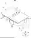


Sources:
- United States Patent and Trademark Office - verify current appl. status at the USPTO↗
Similar patent applications:
- » 20170119207
COOKING APPARATUS, COOKING APPARATUS CONTROLLING SYSTEM, AND METHOD OF CONTROLLING COOKING APPARATUS - » 20210076714
Cooking apparatus, cooking apparatus controlling system, and method of controlling cooking apparatus - » 20210095859
Cooking apparatus, method of controlling the cooking apparatus, and knob of cooking apparatus - » 20230371137
COOKING APPARATUS, METHOD FOR CONTROLLING COOKING APPARATUS, AND KNOB CAPABLE OF CONTROLLING COOKING APPARATUS - » 20230213207
INTERIOR MATERIAL FOR COOKING APPARATUS, COOKING APPARATUS AND METHOD FOR REMOVING STAIN THEREFROM - » 20250302230
TEMPERATURE CONTROL METHOD AND SYSTEM FOR COOKING APPARATUS, COOKING APPARATUS, AND STORAGE MEDIUM - » 20260077432
METHOD FOR SURFACE-TREATING A FUNCTIONAL SURFACE OF A COOKING APPARATUS, AND COOKING APPARATUS FOR COOKING FOOD TO BE COOKED - » 20150196156
Lip seals for cooking apparatus and cooking apparatus having lip seal - » 20090110610
DEODORIZATION DEVICE OF COOKING APPARATUS AND COOKING APPARATUS INCLUDING DEODORIZATION DEVICE - » 20180295677
Method for controlling a heat source belonging to a cooking apparatus and cooking apparatus configured to carry out said method
Recent applications in this class:
- » 20260132935 2026-05-14
MICROWAVE OVEN APPLIANCE AND FILTER ASSEMBLY THEREFOR - » 20260049724 2026-02-19
COOKING APPARATUS - » 20260002675 2026-01-01
INSULATION FOR AN OVEN APPLIANCE AND METHODS OF ASSEMBLING THE SAME - » 20250389425 2025-12-25
ELECTRIC GRILL EQUIPPED WITH DOUBLE AIR CURTAIN-TYPE DUAL AIR PURIFICATION AND CIRCULATION SYSTEM - » 20250389424 2025-12-25
EXHAUST HOOD DEVICE - » 20250383097 2025-12-18
RANGE HOOD - » 20250369627 2025-12-04
ADJUSTABLE FAN FOR A MICROWAVE APPLIANCE - » 20250369626 2025-12-04
ADJUSTABLE FAN FOR A MICROWAVE APPLIANCE - » 20250341317 2025-11-06
HOB WITH CENTRAL DOWNWARD REMOVAL OF COOKING VAPORS THROUGH SUCTION - » 20250334275 2025-10-30
Appliance for cooking dishes
Recent applications for this Assignee:
- » 20260157230 2026-06-04
SEMICONDUCTOR PACKAGE INCLUDING OPTICAL INTEGRATED CIRCUIT CHIP - » 20260157216 2026-06-04
SEMICONDUCTOR PACKAGE - » 20260157210 2026-06-04
SEMICONDUCTOR DEVICE AND METHOD FOR FABRICATING THE SAME - » 20260157201 2026-06-04
ACTIVE INTERCONNECT DIE AND SEMICONDUCTOR PACKAGE INCLUDING THE SAME - » 20260157200 2026-06-04
SEMICONDUCTOR PACKAGE AND METHOD FOR MANUFACTURING THE SAME - » 20260157199 2026-06-04
SEMICONDUCTOR PACKAGE - » 20260157197 2026-06-04
SEMICONDUCTOR PACKAGE - » 20260157168 2026-06-04
SEMICONDUCTOR DEVICES - » 20260157118 2026-06-04
MAGNETIC MEMORY DEVICE, METHOD OF MANUFACTURING THE MAGNETIC MEMORY DEVICE, AND MEMORY APPARATUS INCLUDING THE MAGNETIC MEMORY DEVICE - » 20260157003 2026-06-04
DISPLAY APPARATUS