IMPACT DETECTION SYSTEM INTEGRATED WITH HELMET
US20260165409A1
2026-06-18
18/979,484
2024-12-12
Smart Summary: A helmet is designed with a built-in impact detection system that includes layers for protection and sensors for monitoring. These sensors can sense both outside impacts and the reactions from the wearer's head. A processor analyzes this information to figure out how strong the impact was and where it happened, then calculates the risk of injury. It can send this data to another device for further review. Additionally, the system keeps track of how many impacts occur over time and classifies the risk of injury as minor, moderate, or severe to improve safety. 🚀 TL;DR
Abstract:
This invention relates to an impact detection system integrated within a helmet, comprising an outer shell, inner shell, foam structure, sensors, processor, and communication module. The foam structure is embedded with a plurality of sensors, where a first set detects external impact forces, and a second set detects reactive forces from the wearer's head. A processor determines the intensity and location of impacts, analyses the difference between external and reactive forces, and calculates an injury risk score. The system transmits this data to an external device. The sensors employ a spring-activated conductive mechanism, enabling precise detection. The processor also tracks the frequency and cumulative impact over time, offering real-time injury risk classification as minor, moderate, or severe based on predefined thresholds. The system aims to enhance safety by assessing potential long-term injury risks.
Inventors:
- Saadia Asaf 20 🇮🇳 Aligarh, India
- Mansoor Hasan Khan 21 🇮🇳 Aligarh, India
- Mirza Faizan 9 🇺🇸 Plano, TX, United States
- Maryam Mohmand 1 🇺🇸 Plano, TX, United States
- Reem Khan 1 🇺🇸 Plano, TX, United States
- Rania Khan 1 🇺🇸 Plano, TX, United States
- Amar Gottumukhala 1 🇺🇸 Plano, TX, United States
- Baheej Hamdi 1 🇺🇸 Plano, TX, United States
- Juan Pedro Mendez Saavedra 1 🇺🇸 Plano, TX, United States
- Anika Lal 1 🇺🇸 Plano, TX, United States
- Tanay Sethiya 1 🇺🇸 Plano, TX, United States
- Yazhini Arunprakash 1 🇺🇸 Plano, TX, United States
Applicant:
Interested in similar patents?
Get notified when new applications in this technology area are published.
Classification:
A42B3/046 » CPC main
Helmets; Helmet covers ; Other protective head coverings; Parts, details or accessories of helmets; Accessories for helmets; Detecting, signalling or lighting devices Means for detecting hazards or accidents
A42B3/063 » CPC further
Helmets; Helmet covers ; Other protective head coverings; Parts, details or accessories of helmets; Impact-absorbing shells, e.g. of crash helmets with reinforcing means using layered structures
A42B3/04 IPC
Helmets; Helmet covers ; Other protective head coverings Parts, details or accessories of helmets
A42B3/06 IPC
Helmets; Helmet covers ; Other protective head coverings; Parts, details or accessories of helmets Impact-absorbing shells, e.g. of crash helmets
Description
TECHNICAL FIELD
This disclosure relates generally to an impact detection system, and more particularly to an impact detection system integrated with a helmet, capable of detecting and analyzing external and reactive forces during an impact to assess injury risk.
BACKGROUND
Helmets are widely used in various fields such as sports, construction, military, and other high-risk activities to protect the wearer from head injuries. While modern helmets are designed to absorb and reduce the force of impacts, they do not provide real-time information about the severity or location of impacts, nor do they assess the cumulative effect of repeated impacts over time.
Traditional helmets also fail to provide information regarding the directional force of impacts, which can be crucial for understanding rotational injuries that contribute to concussions and traumatic brain injuries. These helmets are typically passive in nature, relying solely on physical materials like foam or padding to absorb shock, without the capability to track or report on the cumulative effect of multiple impacts over time, which can lead to undetected long-term damage.
Head injuries, particularly concussions, can have severe long-term consequences, and detecting the severity of an impact or repeated impacts can help prevent long-term damage. Thus, there is a need for a helmet system that not only absorbs impact but also monitors and assesses impact-related risks in real time.
SUMMARY
In an embodiment, an impact detection system integrated with a helmet is disclosed. The impact detection system comprises an outer shell forming an external portion of the helmet and configured to receive an external impact force, and an inner shell positioned adjacent to a wearer's head. The impact detection system further comprises a foam structure disposed between the outer shell and the inner shell, such that the foam structure is used to absorb and reduce the force of impact transmitted from the outer shell to the inner shell. The system further comprises a plurality of sensors embedded within the foam structure. The plurality of sensors may include a first set of sensors and a second set of sensors. In an example, the first set of sensors may detect the external impact force transmitted through the outer shell. In response to the external impact force, the second set of sensors may detect a reactive force transmitted from the wearer's head. The impact detection system further comprises a processor operatively connected to the plurality of sensors, such that the processor is configured to determine intensity and a location of an impact of the detected external impact force. The processor also determines a difference between the external impact force detected by the first set of sensors and the reactive force detected by the second set of sensors, and further determines an injury risk score based on an analysis of the difference. The impact detection system further comprises a communication module connected to the processor, such that the communication module is configured to transmit data representing the external impact force, the intensity and location of the impact, and the injury risk score to an external device.
In an embodiment, each sensor of the plurality of sensors comprises a spring activated conductive mechanism.
In a further embodiment, the spring activated conductive mechanism comprises a conductive interface layer, a spring, a metal weight block, and a plurality of metal prongs. The spring is attached to the conductive interface layer via a first end of the spring. The metal weight block is attached to a second end of the spring. The metal weight block is configured to shift in position upon receiving the external impact force.
In another embodiment, the metal weight block is configured to make contact with one or more metal prongs of the plurality of metal prongs based on the shift in the position of the metal weight block upon receiving the external impact force.
In another embodiment, the metal weight block further comprises an electrical power source, such that the current flows from the electrical power source through the metal weight block and to the one or more metal prongs.
In yet another embodiment, the processor is further configured to determine the intensity of the impact force based on the current flowing from the electrical power source.
In another embodiment, the plurality of sensors are arranged in a matrix embedded within the foam structure, where each sensor is positioned at a predetermined location corresponding to a specific region of the helmet, and the processor is further configured to determine the specific region of the helmet as the location of the impact based on a position of a corresponding sensor within the foam structure.
In further embodiment, the processor is further configured to determine a frequency of impacts on the determined specific region of the helmet and generate data indicative of the frequency of impacts on the determined specific region of the helmet. The communication module is further configured to transmit the generated data indicative of the frequency of impacts to the external device.
In an embodiment, the processor is further configured to compare the difference with predefined injury threshold levels stored in a memory and classify injury risk as minor, moderate, or severe based on the comparison.
In an embodiment, the processor is further configured to determine a cumulative impact of the external impact force on a specific region of the helmet over time, generate data indicative of the cumulative impact, and control transmission of the data indicative of the cumulative impact to the external device to assess potential long-term injury risks.
BRIEF DESCRIPTION OF THE DRAWINGS
The present application can be best understood by reference to the following description taken in conjunction with the accompanying drawing figures, in which like parts may be referred to by like numerals.
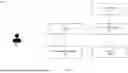
FIG. 1 illustrates a block diagram of an impact detection system integrated with a helmet, in accordance with an embodiment of the present disclosure.
FIG. 2 illustrates a structural diagram of the impact detection system integrated with the helmet of FIG. 1, in accordance with an embodiment of the present disclosure.
FIG. 3 illustrates a structural diagram of a spring activated conductive mechanism, in accordance with an embodiment of the present disclosure.
FIGS. 4A, 4B, 4C and 4D illustrate example scenarios demonstrating multiple impact levels of forces on the spring activated conductive mechanism of FIG. 3, in accordance with an embodiment of the present disclosure.
FIGS. 5A and 5B illustrate example scenarios to detect an electrical signal from the spring activated conductive mechanism of FIG. 3, in accordance with an embodiment of the present disclosure.
FIG. 6 illustrates an example scenario of a graphical user interface associated with an external device, in accordance with an embodiment of the present disclosure.
DETAILED DESCRIPTION OF THE DRAWINGS
The following description is presented to enable a person of ordinary skill in the art to make and use the invention and is provided in the context of particular applications and their requirements. Various modifications to the embodiments will be readily apparent to those skilled in the art, and the generic principles defined herein may be applied to other embodiments and applications without departing from the spirit and scope of the invention. Moreover, in the following description, numerous details are set forth for the purpose of explanation. However, one of ordinary skill in the art will realize that the invention might be practiced without the use of these specific details. In other instances, well-known structures and devices are shown in block diagram form in order not to obscure the description of the invention with unnecessary detail. Thus, the invention is not intended to be limited to the embodiments shown, but is to be accorded the widest scope consistent with the principles and features disclosed herein.
While the invention is described in terms of particular examples and illustrative figures, those of ordinary skill in the art will recognize that the invention is not limited to the examples or figures described. Those skilled in the art will recognize that the operations of the various embodiments may be implemented using hardware, software, firmware, or combinations thereof, as appropriate. For example, some processes can be carried out using processors or other digital circuitry under the control of software, firmware, or hard-wired logic. (The term “logic” herein refers to fixed hardware, programmable logic and/or an appropriate combination thereof, as would be recognized by one skilled in the art to carry out the recited functions.) Software and firmware can be stored on computer-readable storage media. Some other processes can be implemented using analog circuitry, as is well known to one of ordinary skill in the art. Additionally, memory or other storage, as well as communication components, may be employed in embodiments of the invention.
The present invention relates to an impact detection system integrated into a helmet that offers a solution to the common challenge of monitoring and assessing head injury risks in real time, something traditional helmets are unable to do. While existing helmets provide passive protection by absorbing impact forces, they fail to deliver crucial data on the severity, location, and cumulative effect of repeated impacts. This invention addresses these gaps by incorporating a sensor-based system that not only detects the magnitude and direction of impacts but also analyzes the forces transmitted to the wearer's head. By calculating injury risk and transmitting the data to external devices, the system provides immediate feedback, enabling proactive monitoring and intervention to prevent both short-term and long-term brain injuries.
The invention is described in terms of specific examples and accompanied by illustrative figures to better explain its structure and functionality. These examples and figures are intended to aid in understanding the various components, such as the outer shell, inner shell, foam structure, sensors, processor, and communication module, as well as how they interact to detect, analyze, and communicate impact data. The examples provided are for illustration purposes and are not meant to limit the scope of the invention. They demonstrate different configurations of the system and show how the invention can be adapted to various use cases, such as in sports, construction, and military helmets. The illustrative figures help visualize the arrangement of sensors and components, making it easier to grasp the invention's novel approach to monitoring and assessing head impacts.
FIG. 1 illustrates a block diagram of an impact detection system integrated with a helmet, in accordance with an embodiment of the present disclosure. With reference to FIG. 1, there is shown a block diagram 100 that includes an impact detection system 102, a helmet 104, a processor 108, a communication module 110, and an external device 112.
The impact detection system 102 is integrated with the helmet 104 worn by a player or user 106. The helmet 104 serves as the external protective structure that receives impact forces, while the impact detection system 102 monitors both external forces applied to the helmet and the reactive forces transmitted from the user's head. The helmet 104 and the impact detection system 102 are connected in a two-way manner, allowing the detection system to measure both the external impact forces on the helmet 104 and the reactive forces from the user's head. This ensures real-time monitoring of impacts experienced by the user.
In an embodiment, the helmet 104 may further comprise several key components designed to enhance safety during impact events. The outer shell forms the external portion of the helmet and is specifically configured to receive and withstand external impact forces, providing a robust first line of defense against potential hazards. Adjacent to the wearer's head is the inner shell, which serves as the protective barrier directly facing the user's cranium, ensuring comfort while further safeguarding against impact forces. Between these two shells a foam structure is disposed between the inner and the outer shell of helmet 104 that plays a critical role in energy absorption. Specifically the foam is designed to absorb and reduce the force of impact transmitted from the outer shell to the inner shell. By mitigating the energy transferred during an impact, the foam structure significantly lowers the risk of injury to the wearer, making the helmet more effective in protecting against head injuries.
In a further embodiment, the impact detection system 102 is operatively connected to a processor 108, which receives data from the impact detection system 102. The processor 108 is configured to analyze the collected data, including the intensity, location, and difference between external and reactive forces, to assess potential injury risks. Specifically, it processes information related to the intensity and location of the external impacts, as well as the difference between the forces detected externally and those transmitted to the user's head. This analysis allows the processor 108 to determine an injury risk score, evaluate whether the impact exceeds predefined thresholds, and track the cumulative effect of repeated impacts over time.
The processor 108 may include suitable logic, circuitry, and interfaces that may be configured to execute program instructions associated with a set of operations to be executed to determine weight distribution, provide the output signal or control the speaker, the display screen, or the haptic device. The processor 108 may include one or more processing units, which may be implemented as an integrated processor or a cluster of processors that perform the functions of the one or more processing units, collectively. The processor 108 may be implemented based on a number of processor technologies known in the art. Example implementations of the processor 108 may include, but are not limited to, an x86-based processor, a Graphics Processing Unit (GPU), a Reduced Instruction Set Computing (RISC) processor, an Application-Specific Integrated Circuit (ASIC) processor, a Complex Instruction Set Computing (CISC) processor, a microcontroller, a central processing unit (CPU), and/or other computing circuits.
The processor 108 is further connected to the communication module 110, which facilitates the transmission of processed data to an external device 112.
The communication module 110 may use wireless communication technologies, such as Bluetooth or Wi-Fi, to send the data to the external device 112. The external device 112 can be a smartphone, computer, or another monitoring system, enabling real-time feedback and analysis of the impact data.
The communication module 110 may employ various communication protocols, such as Bluetooth, Wi-Fi, NFC (Near Field Communication), Zigbee, or cellular networks (e.g., 3G, 4G, 5G), to transmit data wirelessly. In certain embodiments, the communication module may also support wired communication through interfaces such as USB, Ethernet, or other suitable data transfer methods.
In addition, the communication module 110 may enable the system to send cumulative impact data, historical injury risk data, and real-time updates to cloud-based platforms or remote servers for storage, analysis, and remote monitoring by third-party professionals, such as coaches, doctors, or medical personnel.
The external device 112 serves as the interface through which the processed data is viewed, allowing real-time monitoring of impact events, injury risks, and cumulative impact history.
The external device 112 may be any portable or stationary computing device capable of receiving, processing, and displaying data transmitted from the impact detection system. Such external devices may include, but are not limited to, smartphones, tablets, laptops, wearable devices (e.g., smart watches), or dedicated monitoring systems equipped with communication capabilities (e.g., Bluetooth, Wi-Fi, cellular networks).
The external device 112 may further include an embedded application or software program that processes data received from the impact detection system 102, calculates injury risk levels based on predefined thresholds, and presents the data in a user-friendly interface. Additionally, the external device 112 may be configured to store historical impact data for long-term risk assessment, issue alerts in the event of severe impacts, and trigger automated emergency responses, such as dialing 911, in critical situations. The external device 112 may also be equipped with location services, allowing the system to transmit the real-time location of the user to emergency responders.
In certain embodiments, the external device 112 may also support data sharing functionalities, enabling communication with remote servers or cloud-based systems for further analysis, reporting, or real-time monitoring by authorized personnel, such as medical professionals, coaches, or safety supervisors
Therefore, the impact detection system integrated with helmet 100 offers a solution to the problem of undetected impact severity and cumulative head injuries by providing continuous feedback, risk assessment and helps prevent the long-term consequences of head injuries, ensuring a more informed approach to risk management in high-impact activities.
Although the impact detection system 102 is shown separate from the processor 108 and the communication module 110, a person of ordinary skill in the art may understand that the processor 108 and the communication module 110 may become components of the impact detection system 102.
FIG. 2 illustrates a structural diagram of the impact detection system integrated with the helmet of FIG. 1, in accordance with an embodiment of the present disclosure. With reference to FIG. 2, a diagram 200 refers to the helmet 104 integrated with the impact detection system 102 that may comprise an outer shell 202, an inner shell 206, a foam structure 204 embedded in between outer shell 202 and inner shell 206, or a plurality of sensors 208. For the sake of simplicity of the drawing, the processor 108 and the communication module 110 are not shown in FIG. 2. However, a person of ordinary skill in the art may appreciate that these components can be fairly incorporated in the structure of the helmet 104 or the impact detection system 102 to produce desirable results.
The helmet 104 includes an outer shell 202, which forms the external portion of the helmet 104. This outer shell 202 is made from a durable material configured to receive external impact forces, acting as the first line of defense by absorbing the initial shock of an impact.
Beneath the outer shell 202, the inner shell 206 is positioned adjacent to the wearer's head, providing an additional protective barrier. Between the outer shell 202 and inner shell 206 a foam structure 204 is embedded, which serves as the critical layer for absorbing and reducing the impact force transmitted through the outer shell. The foam is specifically designed to compress and dissipate energy from impacts, minimizing the force that reaches the wearer's head.
Embedded within the foam structure 204 is a plurality of sensors 208, each strategically placed in a matrix arrangement. This matrix ensures that sensors 208 cover multiple regions of the helmet 104, allowing for precise detection of impacts in specific areas. These sensors 208 play a key role in enabling the system's functionality.
In an example, the matrix arrangement of sensors 208 includes a grid-like structure where each sensor is strategically positioned within the foam layer 204 at predetermined intervals. These intervals are based on the desired level of precision and coverage. The matrix arrangement follows a structured pattern, such as rows and columns, where each sensor occupies a unique position.
The sensors 208 are evenly distributed across the foam structure 204 to provide consistent coverage of all areas of the helmet 104. The specific distance between sensors 208 can be determined based on factors such as helmet size, foam thickness, and the resolution required for impact detection.
Each sensor in the matrix is assigned a unique coordinate (such as X and Y values) relative to the helmet structure. This coordinate system helps the processor 108 to easily map the sensor's position to a specific region of the helmet 104. The coordinates allow for accurate detection of the location of an impact based on which sensor or group of sensors is activated. When an impact occurs, the force is transmitted through the outer shell 202 and absorbed by the foam structure 204. The sensors 208 embedded in the foam detect the force as it passes through. One or more sensors in the region of the helmet where the impact occurs will register the force. Each sensor in the matrix has a predefined position based on its coordinates in the grid. When a particular sensor or set of sensors detects an impact, the coordinates of the activated sensor(s) are sent to the processor 108.
In addition to the spring-activated conductive sensors 208 described in the current embodiment, several other types of sensors can be well-suited for the impact detection system integrated with a helmet. One suitable option is piezoelectric sensors, which generate electrical charge in response to mechanical stress, making them ideal for detecting impact forces. These sensors are highly sensitive and can provide real-time data on the magnitude of impacts. Another suitable option includes accelerometers, which measure the rate of change of velocity upon impact and can help in detecting both the direction and intensity of the force.
Pressure sensors are another valuable addition. These sensors can be integrated within the foam structure to detect changes in pressure at various points within the helmet, providing an accurate measure of localized impact forces. Strain gauges can also be employed to detect deformation in the helmet's materials under impact. As they change resistance when stretched or compressed, they offer precise data on how the helmet's structure reacts to forces.
Finally, capacitive force sensors could be implemented to detect changes in capacitance as the foam structure compresses under impact, offering a different method of impact force detection that is both sensitive and scalable. These sensors, when combined with the system's processor, could enhance the overall accuracy and range of impact data, providing more comprehensive injury risk analysis.
The processor 108 uses the coordinates of the activated sensors to determine the exact region of the helmet where the impact occurred. This can be done by cross-referencing the sensor's position within the matrix with the corresponding area of the helmet (e.g., front, side, top, etc.). If multiple sensors are activated simultaneously, the processor may use an interpolation algorithm to estimate the precise point of impact within the region.
The processor 108 may pinpoint the specific region of the helmet 104 that was impacted, allowing for precise localization. For example, if the helmet 104 is divided into zones, the processor 108 will be able to report which zone (such as the left front quadrant) sustained the impact.
The sensors 208 may include a first set of sensors and a second set of sensors each being positioned differently inside the foam structure 204.
The first set of sensors is configured to detect the external impact force as it is transmitted through the outer shell 202. When an impact occurs, these sensors 208 measure the magnitude and location of the force exerted on the outer shell 202.
Simultaneously, a second set of sensors 208, also embedded within the foam structure 204, is designed to detect the reactive force that is transmitted from the wearer's head in response to the impact.
In effect, the combination of the first set and the second set of sensors measure how much force has passed through the foam layer and been absorbed by the inner shell 206, giving a real-time assessment of the risk to the wearer's head.
In an embodiment, the impact detection system 102 utilizes the first set of sensors embedded within the foam structure 204 to measure the external impact force applied to the outer shell 202. These sensors provide data about the magnitude and location of the force on the helmet's external surface. Simultaneously, the second set of sensors, also embedded within the foam structure 204, detects the reactive force transmitted from the wearer's head, as the force passes through the foam layer and reaches the inner shell 206. The difference between the external impact force and the reactive force transmitted from the wearer's head indeed provides a direct indication of the force that is actually being absorbed by the wearer's head, which is the force responsible for causing potential deformation or injury.
If the force difference is small, meaning the reactive force is still quite close to the external impact force, it implies that the helmet is not absorbing a sufficient amount of the impact. A higher portion of the original impact force is directly affecting the head, which could lead to greater deformation of the skull and brain tissues, increasing the likelihood of serious injury such as concussions or fractures.
On the other hand, if the force difference is large, the helmet's protective foam structure is doing its job effectively, absorbing a significant amount of the impact, thereby reducing the force that reaches the head. This results in less deformation and a reduced chance of injury.
The impact detection system 102 or the processor 108 may use this difference in forces to calculate the severity of potential injury. Small force difference indicates high risk of injury as the head absorbs a larger amount of the impact. Large force difference indicates effective energy absorption by the helmet, meaning a lower risk of injury.
By analyzing this force difference, the processor 108 may generate real-time data indicating the risk level of injury. This can be further quantified by threshold comparison such that predefined thresholds can classify the severity of injury (e.g., mild, moderate, severe) based on how much of the impact force is absorbed by the head. Additionally, the processor 108 may generate deformation prediction information with machine learning algorithms trained to predict the extent of deformation in brain tissue or skull bones and translating the force into expected injury types.
This real-time analysis can be transmitted to an external device (such as a smartphone or monitoring system), for example, the external device 112, to provide immediate feedback on the potential for injury. For example, in sports, this could alert medical staff to remove a player from the game for evaluation. In construction or military settings, it could trigger automatic safety mechanisms or warnings when the risk of severe head injury is detected.
In another example, this real-time analysis of the difference in forces allows the processor 210 to calculate the severity of the impact and evaluate the potential injury risk. For instance, if the external force exceeds a certain threshold but the difference is minimal, the processor can classify the injury risk as severe, signaling that the wearer might be at greater risk of head trauma. The injury data can then be transmitted to an external device via the communication module 110 for further analysis or immediate action, such as alerting emergency services.
The arrangement of these sensors 208 is crucial to the system's functionality, as each sensor 208 corresponds to a specific region of the helmet 104. This configuration allows identifying not only the magnitude of an impact but also its precise location, enabling a more detailed analysis of potential injury risk. The combined use of external and reactive force sensors 208 ensures that the system accurately tracks the severity and potential consequences of head impacts, providing comprehensive protection for the wearer.
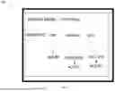
FIG. 3 illustrates a structural diagram of a spring activated conductive mechanism, in accordance with an embodiment of the present disclosure. With reference to FIG. 3, there is shown a diagram 300 that includes spring activated conductive mechanism 302-1 and 302-2 such that each of the spring activated conductive mechanism 302-1 or 302-2 may include a conductive interface layer 304-1 or 304-2, a spring 306-1 or 306-2, a metal weight block 308-1 or 308-2, and metal prongs 310-1 or 310-2.
In an embodiment, each of the sensors 208 as described in the description of FIG. 2 may include the spring activated conductive mechanism 302-1 or 302-2. In an example scenario, however not limited to, the spring activated conductive mechanism may be oriented as illustrated by elements 302-1 or 302-2. In an example, however not limited to, the spring activated conductive mechanism 302-1 is strategically placed with the foam structure to receive the external impact force received from the outer shell 202 of the helmet 104. This strategic placement of the spring activated conductive mechanism 302-1 enables the movement of the spring 306-1 in a downward direction towards the metal prongs 310-1, thereby detecting the intensity of the external impact force acting towards the head of the helmet 104 wearer.
In an embodiment, the impact detection system 102 of FIG. 1 may include the plurality of sensors 208 grouped into the first set of sensors and the second set of sensors. The first set of sensors may include sensors 208 with the spring activated conductive mechanism 302-1. The second set of sensors may include sensors 208 with the spring activated conductive mechanism 302-2. The first set of sensors may detect the external impact force from the outer shell 202 of the helmet 104 while the second set of sensors may detect a reactive force coming from the wearer's head. More specifically, upon detecting external impact forces, the second set of sensors responds by measuring the reactive forces transmitted from the wearer's head, allowing for a comprehensive assessment of the impact event.
Each of the spring activated conductive mechanisms 302-2 comprises the conductive interface layer 304-2 connected to the spring 306-2, with one end of the spring 306-2 attached to the interface layer and the other end linked to a metal weight block 308-2. This metal weight block 308-2 is designed to shift in position when an external impact force is applied, creating a responsive detection capability.
Each of these prongs (310-2a, 310-2b, and 310-2c) forms a part of a second set of sensors 208 designed to detect reactive forces transmitted from the wearer's head in response to external impacts. This allows the system to gauge the differential forces acting on the helmet 104 and the user's head, thereby providing a comprehensive understanding of the impact dynamics.
When the metal weight block 308-2 shifts due to an impact, it is configured to make contact with one or more metal prongs 310-2 in the sensor mechanism. This contact occurs based on the weight block's 308-2 position after receiving the external impact force, thereby completing the electric path between the metal weight block 308-2 and the metal prongs 310-2.
To ensure functionality, the impact detection system 102 includes an electrical power source that facilitates current flow through the metal weight block 308-2 and the metal prongs 310-2. This flow of current is crucial for the operation of the sensors 208, enabling them to accurately detect and report the forces experienced during an impact.
When an impact occurs, the spring activated conductive mechanism which includes a spring attached to a metal weight block, is activated. The metal weight block movement is contingent upon the magnitude of the impact force.
FIGS. 4A, 4B, 4C, and 4D illustrate example scenarios demonstrating multiple impact levels of forces on the spring activated conductive mechanism of FIG. 3, in accordance with an embodiment of the present disclosure.
As illustrated by FIG. 4A, when a force F1 is applied, which represents a minimal impact, the metal weight block 308-1 does not make contact with any of the metal prongs 310-1. In this scenario, the impact is insufficient to trigger a reaction, indicating that the force is within a safe threshold.
As illustrated by FIG. 4B, when a greater force F2 is applied, exceeding the threshold of force F1, the metal weight block 308-1 shifts and impacts the first metal prong 310-1a. As can be seen by FIG. 5A, the scenario of FIG. 4B is extended to include an electrical power source 502 to demonstrate how electrical signal 504 flows in the electric path created due to the contact between the metal weight block 308-1 and the first metal prong 310-1a. This contact between the metal weight block 308-1 and first metal prong 310-1a completes an electric path to generate an electrical signal 504 that flows from the electrical power source 502 via the conductive interface layer 304-1, the metal spring 306-1, the metal weight block 308-1, and the metal prong 310-1a. Each of the metal prongs is flexible and metal-coated for conducting electricity. The current flow through this prong corresponds to the intensity of the impact, allowing the system to quantify the external force. The method illustrated in FIG. 5A, to detect the electrical signal when a spring actuated conductive mechanism or a sensor is activated due to the impact of an external force, is equally applicable to each and every example scenario defined throughout this disclosure.
As illustrated by FIG. 4C, if an even more significant force F3 occurs, which surpasses the force F2, the metal weight block 308-1 will then strike both the first metal prong 310-1a and the second metal prong 310-1b. This event not only signifies an increase in impact severity but also generates a correspondingly higher electrical signal. The impact detection system 102 utilizes the variation in current flow and amount to distinguish between different levels of impact, enabling it to assess the severity of the force applied. As can be seen by FIG. 5B, the scenario of FIG. 4C is extended to include an electrical power source 502 to demonstrate how electrical signal 504 flows in the electric path created due to the contact between the metal weight block 308-1, the first metal prong 310-1a and the second metal prong 310-1b simultaneously. The electrical circuit is established when the metal weight block 308-1 simultaneously makes contact with both the first metal prong 310-1a and the second metal prong 310-1b. This contact forms a closed parallel resistive circuit. In a parallel circuit, the total current is the sum of the currents passing through each parallel path (here, through prongs 310-1a and 310-1b). Since each prong offers a separate conductive pathway for the electric current, the overall resistance of the system decreases. In an example, the metal prongs 310 have equal resistance values.
With reduced total resistance, the current drawn from the electrical power source 502 increases. The system becomes more conductive because the parallel configuration allows more pathways for current flow. As force is applied, the strength and consistency of the contact improve, reducing the overall resistance further. The processor 108 monitors this increase in current flow and translates these variations into data reflecting the magnitude of the applied force. As more current flows through the prongs due to decreased resistance, the processor 108 interprets this change as indicative of greater force being applied. This relationship between resistance, current, and force allows the system to measure and quantify the applied force in real-time, enhancing the accuracy of the system's analysis.
As illustrated by FIG. 4D, when a greater force F4 is applied, exceeding the threshold of force F3, The metal weight block 308-1 moves and makes contact with the third metal prong 310-1c. This contact generates an electrical signal, with the flexible and metal-coated prong conducting electricity. This event not only signifies an increase in impact severity but also generates a correspondingly higher electrical signal. The current flow through this prong 310-1 corresponds to the intensity of the impact, allowing the system to quantify the external force.
By measuring the intensity of the current generated as explained with the reference of FIG. 5A and FIG. 5B when the metal weight block contacts the prongs, the impact detection system 102 can accurately evaluate the magnitude of the impact forces. The correlation between the amount of current and the impact severity enables the processor 108 to analyze the overall impact data effectively. The processor 108 calculates the risk factor score by analyzing the electrical current generated by the spring-activated conductive mechanism in response to different impact forces, such as F2, F3, or F4. When an impact occurs, the metal weight block 308-2 inside the sensor 208 shifts due to the force, and depending on the magnitude of the force, it makes contact with one or more metal prongs 310-2. Each prong represents a threshold of force, with higher forces causing the metal weight block 308-2 to contact additional prongs 310-2, generating varying levels of electrical current. For instance, a moderate force like F2 might cause the bob to touch the first prong 310-2a, producing a lower current, whereas a higher force like F3 or F4 results in the bob hitting the second or third prong, generating a proportionally higher current.
The processor 108 receives this current as a direct indication of the impact force. It is programmed to interpret the current levels and correlate them with specific force thresholds stored in its memory. By measuring the current, the processor can accurately determine the intensity of the impact force. Additionally, it compares the external force (detected by the first set of sensors 208) with the reactive force (detected by the second set of sensors 208) to assess how much force is absorbed by the helmet 104 versus what is transmitted to the wearer's head.
Once the processor 108 determines the magnitude of the impact, it compares the force data against predefined injury risk thresholds to calculate a risk factor score. These thresholds are set according to the typical severity of head injuries associated with different force levels. For example, a force corresponding to F2 might indicate a low risk, while forces like F3 or F4, generating higher current and thus indicating more severe impacts, could trigger moderate or high-risk warnings. The processor then assigns a risk score based on the comparison and sends this data to the external device 112, alerting users if the impact is potentially dangerous. This entire process ensures that the system provides real-time, accurate risk assessments based on the electrical current generated by the spring mechanism, allowing for immediate intervention when necessary. By monitoring the frequency and intensity of repeated impacts on specific regions of the helmet, the processor 108 can assess long-term risks, such as the potential for chronic traumatic encephalopathy (CTE) or other cumulative brain injuries.
In an example, the processor 108 continuously monitors sensor data to detect whenever an impact occurs on a specific region of the helmet 104. The matrix arrangement of sensors 208 ensures that the processor 108 can identify which region of the helmet 104 receives an impact based on sensor activation patterns. The processor 108 maintains a log of impact events to calculate the frequency at which impacts occur on that specific region.
In an embodiment, each time an impact is detected, the processor 108 records the timestamp of the event and associates it with the corresponding region of the helmet 104 where the impact was registered. Over time, the processor 108 uses this data to calculate the frequency of impacts by analysing the time intervals between consecutive impacts in the same region.
In an embodiment, the processor 108 generates data indicative of the frequency of impacts for the specific region of the helmet 104, which could be useful for understanding patterns of repeated impacts. This data may be useful in real-time or over a period of time to indicate how often a particular region of the helmet 104 experiences force, helping to identify vulnerable areas that may be prone to damage.
In an additional embodiment, the communication module 110 is configured to transmit the frequency data to an external device 112, such as a mobile application, healthcare platform, or cloud storage. This data can then be analysed to understand helmet wear patterns and potentially identify any issues in helmet design or fit that make certain areas more prone to impact.
In a further embodiment, the impact detection system may include a memory to store predefined injury thresholds. These thresholds correspond to different levels of impact that may cause minor, moderate, or severe injury to the wearer. The thresholds are based on medical data or studies correlating the magnitude of forces to potential injuries. The processor 108 may compare the calculated difference in forces (external impact force vs. reactive force) with the predefined thresholds stored in the memory. Based on this comparison, the processor 108 may determine whether the injury risk is minor, moderate, or severe.
The processor 108 may classify the injury risk level into three categories, for example, minor: if the force difference is below a certain threshold; moderate: if the force difference falls within a defined middle range; or severe: if the force difference exceeds a high-impact threshold. This classification is then used to trigger notifications or alarms that can alert the wearer or healthcare personnel to the potential risk of injury.
In a further embodiment, the processor 108 may further monitor the cumulative impact over time for specific regions of the helmet 104. This functionality is important for understanding the long-term effects of repeated impacts, which could lead to chronic injuries even if individual impacts are not severe. Each time an impact is detected, the processor 108 calculates the force absorbed by the helmet 104 and adds this value to a cumulative total for that specific region. The total reflects the cumulative stress experienced by the helmet 104 and the wearer's head in that region over time. The processor 108 may generate data indicative of the cumulative impact, which includes the sum of all forces experienced in a particular region of the helmet. The cumulative data can be used to assess potential long-term injury risks, especially in cases where a wearer experiences multiple minor or moderate impacts over time that might add up to a more serious injury.
In an example, the communication module 110 may transmit the cumulative impact data to an external device for further analysis. This data can be used by healthcare professionals to assess the wearer's exposure to impacts over time and may serve as an early warning system for wearers at risk of developing chronic conditions, such as concussions or traumatic brain injuries (TBI).
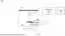
FIG. 6 illustrates an example scenario of a graphical user interface (GUI) associated with an external device, in accordance with an embodiment of the present disclosure. With reference to FIG. 6, there is shown a GUI 600 associated with the external device 112 which operates in conjunction with the impact detection system 102. The GUI 600 can be associated with various types of external devices, such as a smartphone, a tablet, or any software application installed on a personal computer, wearable device, or dedicated monitoring system. The external device 112 serves as a hub for receiving, analyzing, and displaying real-time data from the helmet's impact detection system 102. The external device 112 is capable of wireless communication, data processing, and user interface display, ensuring efficient interaction between the system and users, whether they are athletes, coaches, medical personnel, or safety supervisors.
This communication typically occurs via wireless protocols, such as Bluetooth, Wi-Fi, or cellular networks, depending on the range and data requirements of the system. The communication module 110 is responsible for transmitting the processed data including the intensity, location of impact, injury risk scores, and cumulative impact data directly to the external device. Once the data is received, the external device displays this information through a user-friendly graphical user interface 500, allowing users to view real-time impact reports, injury risk alerts, and historical data trends.
The external device 112 incorporates an intelligent feature that identifies the type of activity or sport the user is engaged as a system mode, such as football, motorbike riding, or any other high-risk activity, and adjusts the impact force thresholds and injury risk calculations accordingly. This functionality is enabled through a game or activity selection interface within the device's software. When a user selects a specific sport or activity, such as football, motorcycling, or skiing, the external device automatically adjusts its internal algorithms to account for the typical range and nature of impacts associated with that activity.
For example, in football, where head-to-head or head-to-ground collisions are more frequent but less severe compared to motorbike accidents, the injury risk score will be calculated based on predefined thresholds that consider the force, frequency, and type of impacts expected in football. In contrast, for motorbike riders, the device would anticipate higher-impact forces due to potential high-speed collisions, and therefore, the injury risk score would reflect these different dynamics.
The external device 112 plays a crucial role in the overall functionality of the impact detection system by offering several advanced features that enhance user safety and awareness. One of its primary functions is real-time monitoring, where users can instantly view data related to head impacts as they happen. Whether during a game, on a construction site, or in a military operation, this real-time capability offers immediate feedback about the location, intensity, and potential injury risks of any head impact, allowing for swift responses.
In addition, the external device 112 enables impact history tracking, allowing users to review historical data that captures the frequency and severity of impacts over time. This feature is invaluable for long-term risk assessment, especially in activities where repeated impacts can accumulate to dangerous levels (low, medium and high) , such as in contact sports or hazardous work environments.
The external device 112 also provides injury risk alerts, which are triggered when impacts surpass predefined safety thresholds. This early warning can help users take immediate action to prevent further injuries, serving as a critical preventative measure in high-risk situations.
The external device 112 in the impact detection system 102 incorporates an emergency auto-dial feature that automatically calls 911 when a severe injury is detected based on impact severity data. This functionality is enabled through a combination of software algorithms, communication protocols, and device capabilities. The processor 108 monitors the impact forces and calculates an injury risk score. If the score surpasses a predefined threshold, indicating a severe injury, the data is transmitted to the external device 112 via Bluetooth, Wi-Fi, or cellular networks. The external device 112, which could be a smartphone or dedicated monitoring system, runs an embedded application that assesses the severity of the injury based on stored thresholds. Upon identifying a severe injury, the application triggers the device's auto-dialer by interfacing with the native telephony system or built-in communication module, automatically dialing 911.
In a further embodiment, the external device 112 is global positioning system (GPS) enabled to transmit the wearer's real-time location to emergency responders. The external device 112 may include a GPS module to retrieve real-time location of the helmet wearer and transmit the retrieved real-time location to emergency responders such as relatives, nearby hospitals, or friends. To prevent false alarms, the software may introduce a brief delay or a confirmation screen, but if unacknowledged, the emergency call proceeds. The call is made through standard cellular or VoIP protocols, depending on the connectivity options of the external device 112.
Finally, the external device 112 offers powerful tools for data analysis and visualization. Through an intuitive graphical user interface (GUI) 500, users can view data in the form of easy-to-read graphs, charts, and maps that show the helmet's impact history, injury risk levels, and which regions of the helmet are most affected. This visual representation allows users to interpret complex data at a glance, making it easier to understand patterns and trends that could indicate potential risks, enabling informed decision-making for both immediate safety and long-term health.
It will be appreciated that, for clarity purposes, the above description has described embodiments of the invention with reference to different functional units and processors. However, it will be apparent that any suitable distribution of functionality between different functional units, processors or domains may be used without detracting from the invention. For example, functionality illustrated to be performed by separate processors or controllers may be performed by the same processor or controller. Hence, references to specific functional units are only to be seen as references to suitable means for providing the described functionality, rather than indicative of a strict logical or physical structure or organization.
Although the present invention has been described in connection with some embodiments, it is not intended to be limited to the specific form set forth herein. Rather, the scope of the present invention is limited only by the claims. Additionally, although a feature may appear to be described in connection with particular embodiments, one skilled in the art would recognize that various features of the described embodiments may be combined in accordance with the invention.
Furthermore, although individually listed, a plurality of means, elements or process steps may be implemented by, for example, a single unit or processor. Additionally, although individual features may be included in different claims, these may possibly be advantageously combined, and the inclusion in different claims does not imply that a combination of features is not feasible and/or advantageous. Also, the inclusion of a feature in one category of claims does not imply a limitation to this category, but rather the feature may be equally applicable to other claim categories, as appropriate.
Claims
What is claimed is:1. An impact detection system integrated with a helmet, comprising:
an outer shell forming an external portion of the helmet and configured to receive external impact force;
an inner shell positioned adjacent to a wearer's head;
a foam structure disposed between the outer shell and the inner shell, wherein the foam structure is configured to absorb and reduce the force of impact transmitted from the outer shell to the inner shell;
a plurality of sensors embedded within the foam structure, wherein
a first set of sensors of the plurality of sensors is configured to detect the external impact force transmitted through the outer shell, and
in response to the external impact force, a second set of sensors of the plurality of sensors is configured to detect a reactive force transmitted from the wearer's head; and
a processor operatively connected to the plurality of sensors, wherein the processor is configured to:
determine an intensity and a location of an impact of the detected external impact force;
determine a difference between the external impact force detected by the first set of sensors and the reactive force detected by the second set of sensors; and
determine an injury risk score based on an analysis of the difference;
a communication module connected to the processor, wherein the communication module is configured to transmit data representing the external impact force, the intensity and location of the impact, and the injury risk score to an external device.
2. The system of claim 1, wherein each sensor of the plurality of sensors comprises a spring activated conductive mechanism.
3. The system of claim 2, wherein the spring activated conductive mechanism comprises:
a conductive interface layer;
a spring attached to the conductive interface layer via a first end of the spring;
a metal weight block attached to a second end of the spring, the metal weight block being configured to shift in position upon receiving the external impact force; and
a plurality of metal prongs.
4. The system of claim 3, wherein the metal weight block is configured to make contact with one or more metal prongs of the plurality of metal prongs based on the shift in the position of the metal weight block upon receiving the external impact force.
5. The system of claim 4, further comprising an electrical power source, wherein current flows from the electrical power source through the metal weight block and the one or more metal prongs.
6. The system of claim 1, wherein the processor is further configured to determine the intensity of the impact force based on the current flowing from the electrical power source.
7. The system of claim 1, wherein
the plurality of sensors is arranged in a matrix embedded within the foam structure,
each sensor is positioned at a predetermined location corresponding to a specific region of the helmet, and
the processor is further configured to determine the specific region of the helmet as the location of the impact based on a position of a corresponding sensor within the foam structure.
8. The system of claim 1, wherein
the processor is further configured to:
determine a frequency of impacts on the determined specific region of the helmet; and
generate data indicative of the frequency of impacts on the determined specific region of the helmet, and
the communication module is further configured to transmit the generated data indicative of the frequency of impacts to the external device.
9. The system of claim 1, wherein the processor is further configured to:
compare the difference with predefined injury threshold levels stored in a memory; and
classify injury risk as minor, moderate, or severe based on the comparison.
10. The system of claim 1, wherein the processor is further configured to:
determine a cumulative impact of the external impact force on a specific region of the helmet over time;
generate data indicative of the cumulative impact; and
transmit the data indicative of the cumulative impact to the external device to assess potential long-term injury risks.
Images & Drawings included:


Sources:
- United States Patent and Trademark Office - verify current appl. status at the USPTO↗
Recent applications in this class:
- » 20260137155 2026-05-21
Surround-Vision Safety Headgear System - » 20250380761 2025-12-18
Helmet Collision Safety System - » 20250185746 2025-06-12
METHOD AND SYSTEM OF DETERMINING POSITION AND ORIENTATION OF A HELMET - » 20250143399 2025-05-08
HAPTIC ENABLED SMART HELMET FOR ENHANCED SAFETY - » 20240415222 2024-12-19
METHOD AND SYSTEM FOR PROVIDING ALERTS TO A USER - » 20240381966 2024-11-21
HAPTIC ENABLED SMART HELMET FOR ENHANCED SAFETY - » 20240237776 2024-07-18
HELMET FOR MONITORING RIDER CONDITION - » 20240215675 2024-07-04
Identifying true positive data within a set of blast exposure data - » 20240197021 2024-06-20
PORTABLE SMART AIR HELMET - » 20240081457 2024-03-14
Voltage Detection Devices and Systems