MODULAR SEATING ASSEMBLY
US20260165482A1
2026-06-18
19/436,574
2025-12-30
Smart Summary: Modular seating assemblies are designed to be comfortable and easy to adjust. They have a base with a central frame and side panels that support a seat pan. The seat pan can be attached in different ways to create either flat or sloped seating without needing tools. Some versions come with covers and special features that help connect multiple seating units together. This design makes it simple to customize seating arrangements for different needs. 🚀 TL;DR
Abstract:
The present disclosure relates to modular seating assemblies configured to provide ergonomic pitched seating and improved construction. A seating assembly includes a base with a central frame, side panels, and corner pillars, where the seat base defines multiple engagement surfaces or shelves for selectively supporting a seat pan. The seat pan can be re-engaged with the base in various orientations to provide level or pitched seating configurations without mechanical adjustment mechanisms. In certain embodiments, the assembly includes an outer cover with inserts for alignment, bi-directional suspension within the seat pan, and soft-edge or modular connection features that allow coupling between adjacent bases.
Inventors:
- Shawn D. Nelson 37 🇺🇸 Washington, UT, United States
- David M. Underwood 35 🇺🇸 Hurricane, UT, United States
- Tyler Sanders 8 🇺🇸 St. George, UT, United States
- Joel H. Bennett 6 🇺🇸 Morgan, UT, United States
- Tanner Rick Wheadon 5 🇺🇸 Washington, UT, United States
- Benjamin Jay Sharp 2 🇺🇸 Washington, UT, United States
Applicant:
Interested in similar patents?
Get notified when new applications in this technology area are published.
Classification:
A47C7/287 » CPC main
Parts, details, or accessories of chairs or stools; Seat parts with tensioned springs, e.g. of flat type with combinations of different types flat type tensioned springs
A47C13/005 » CPC further
Convertible chairs, stools or benches Modular seating
A47C7/28 IPC
Parts, details, or accessories of chairs or stools; Seat parts with tensioned springs, e.g. of flat type
A47C13/00 IPC
Convertible chairs, stools or benches
Description
CROSS-REFERENCE TO RELATED APPLICATIONS
This application is a continuation-in-part of: (1) U.S. patent application Ser. No. 19/413,715, filed on Dec. 9, 2025, entitled Modular Seating Assembly, which claims priority to and the benefit of U.S. Provisional Patent Application No. 63/734,530, filed on Dec. 16, 2024, entitled Modular Seating Assembly, (2) U.S. patent application Ser. No. 19/413,752, filed on Dec. 9, 2025, entitled Cushioning for Ergonomic Seating, which claims priority to and the benefit of U.S. Provisional Patent Application No. 63/734,530, filed on Dec. 16, 2024, entitled Modular Seating Assembly, and (3) U.S. patent application Ser. No. 19/413,780, filed on Dec. 9, 2025, entitled Furniture Base with Removable Floor and Storage, which claims priority to and the benefit of U.S. Provisional Patent Application No. 63/734,530, filed on Dec. 16, 2024, entitled Modular Seating Assembly. All of the foregoing applications are incorporated herein by reference in their entirety.
BACKGROUND
1. Technical Field
The present disclosure relates generally to furniture systems, and more particularly to modular seat constructions that allow for adjustable pitch configurations, tool-free assembly and disassembly, and compact shipping. In certain implementations, the disclosure relates to modular seat bases, seat pans, and support frames configured to provide variable seating angles and enhanced user comfort while maintaining manufacturing and logistical efficiency.
2. Background and Relevant Art
Conventional modular furniture is often primarily designed around spatial flexibility rather than ergonomic customization. Typical modular seating systems allow users to add, remove, or rearrange units to fit a desired room layout, but the structural configuration of each module is generally uniform and unchangeable. This uniformity simplifies manufacturing and assembly, yet it limits a user's ability to personalize comfort or adjust seating ergonomics, i.e., by modifying the furniture after purchase better suit individual preferences or intended uses. Accordingly, in cases where a modular system may provide customization, it is often provided through different SKU variants of the interchangeable members. As a result, traditional modular assemblies can feel static, rigid, or ergonomically generic, offering little ability to tailor the seating experience beyond basic arrangement.
Additionally, weight and bulk remain persistent challenges in modular furniture. Modular bases are often constructed from solid or over-reinforced components to ensure structural stability across various configurations, which can make the furniture heavy and difficult to move. This can hinder both shipping efficiency and user maneuverability within a space. This can also cause shipping and packaging to be cumbersome, as large and irregularly shaped cushions and bases frequently require oversized cartons or multiple shipments.
Accordingly, there are a number of shortcomings in the field of modular furniture assemblies.
The subject matter described herein is not limited to embodiments that operate only in environments such as those described above. Rather, this background is only provided to illustrate one example technology area where some embodiments described herein can be practiced.
BRIEF SUMMARY
The present disclosure can comprise systems, methods, and apparatus for constructing modular seating assemblies for providing pitched or level seating. For example, a modular seating assembly configured for providing level or pitched seating, the modular seating assembly can include a seat base and a seat pan configured to provide a seating surface in: (i) a level configuration that is substantially parallel to a support surface on which the seat base is mounted; or (ii) a pitched configuration in which the seating surface is positioned at an angle relative to the support surface on which the seat base is mounted. The user can selectively mount the seat pan in the level configuration or the pitched configuration.
In another embodiment, a modular seating assembly configured for providing level or pitched seating, the modular seating assembly can include a seat base. The seat base can include a central frame where the central frame has an upper surface, a side panel where the side panel is secured to the central frame, and a corner pillar where the corner pillar comprises a shelf. The modular seating assembly can also include a seat pan configured to provide a seating surface, in: (i) a level configuration that is substantially parallel to a support surface on which the seat base is mounted; or (ii) a pitched configuration in which the seating surface is positioned at an angle relative to the support surface on which the seat base is mounted. Furthermore, when in the pitched configuration, the seat pan engages both the shelf and the upper surface.
In another embodiment, a modular seating assembly configured for providing pitched seating can include a seat base. The seat base can include a central frame having a first edge, a side panel secured to the first edge, and a corner pillar secured to a portion of the first edge. The seat pan can provide a seating surface in either a level configuration or a pitched configuration. Furthermore, the modular seating assembly can include an outer cover configured to wrap around the seat base, and the outer cover can include an insert, wherein the insert is configured to be positioned at a first end of the side panel when the outer cover is installed around the seat base.
In another embodiment, a seat pan for use in a modular seating assembly, the seat pan can include a central frame and a suspension means. The suspension means can include a non-stretching central region, a first stretching region that extends outward from the non-stretching central region, and a second stretching region that extends outward from the non-stretching central region in a direction opposite the first stretching region. The seat pan can also include a corner coupler. The first stretching region and the second stretching region can each elastically deform around the central frame to couple the suspension means to the central frame. Additionally, the corner coupler secures the suspension means to the central frame at a corner of the central frame.
In another embodiment, a modular seating assembly configured for providing pitched seating, the modular seating assembly can include a seat base. The seat base can include a first side panel and a second side panel positioned perpendicular to the first side panel. Further, an end of the first side panel and an end of the second side panel define a gap. The modular seating assembly can also include a removable outer cover. The removable outer cover can include an insert, and the insert can be positioned within the gap. Thus, the insert can provide a soft corner to the seat base.
Additional features and advantages of exemplary implementations of the invention will be set forth in the description which follows, and in part will be obvious from the description, or can be learned by the practice of such exemplary implementations. The features and advantages of such implementations can be realized and obtained by means of the instruments and combinations particularly pointed out in the appended claims. These and other features will become more fully apparent from the following description and appended claims, or can be learned by the practice of such exemplary implementations as set forth hereinafter.
BRIEF DESCRIPTION OF THE DRAWINGS
In order to describe the manner in which the above recited and other advantages and features of the invention can be obtained, a more particular description of the invention briefly described above will be rendered by reference to specific embodiments thereof, which are illustrated in the appended drawings. Understanding that these drawings depict only typical embodiments of the invention and are not therefore to be considered to be limiting of its scope, the invention will be described and explained with additional specificity and detail through the use of the accompanying drawings in which:
FIG. 1 illustrates a perspective of a modular seating assembly according to an implementation of the present disclosure;
FIG. 2 illustrates a perspective view of a seat base, according to an implementation of the present disclosure;
FIG. 3 illustrates a top-down facing view of a seat base according to an implementation of the present disclosure;
FIG. 4 illustrates an exploded view of a seat base according to an implementation of the present disclosure;
FIG. 5 illustrates a cross-sectional view of a seat base according to an implementation of the present disclosure;
FIG. 6A illustrates a seat base and a base cover according to an implementation of the present disclosure;
FIG. 6B illustrates a seat base including one or more end caps according to an implementation of the present disclosure;
FIG. 6C illustrates a close-up view of a corner of the seat base of FIG. 6B;
FIG. 6D illustrates a perspective view of the corner shown in FIG. 6C;
FIG. 7 illustrates a perspective view of a seat base, according to an implementation of the present disclosure;
FIG. 8 illustrates a top-down facing view of a seat base according to an implementation of the present disclosure;
FIG. 9 illustrates an exploded view of a seat base according to an implementation of the present disclosure;
FIG. 10 illustrates a cross-sectional view of a seat base according to an implementation of the present disclosure;
FIG. 11 illustrates another embodiment of a seat base according to an implementation of the present disclosure;
FIG. 12 illustrates yet another embodiment of a seat base according to an implementation of the present disclosure;
FIG. 13A illustrates an embodiment of a central frame according to an implementation of the present disclosure;
FIG. 13B illustrates another embodiment of a central frame according to an implementation of the present disclosure;
FIG. 13C illustrates yet another embodiment of a central frame according to an implementation of the present disclosure;
FIG. 13D illustrates still another embodiment of a central frame according to an implementation of the present disclosure;
FIG. 14A illustrates an embodiment of a seat pan according to an implementation of the present disclosure;
FIG. 14B illustrates another embodiment of a seat pan according to an implementation of the present disclosure;
FIG. 14C illustrates yet another embodiment of a seat pan according to an implementation of the present disclosure;
FIG. 14D-1 illustrates still another embodiment of a seat pan according to an implementation of the present disclosure;
FIG. 14D-2 illustrates a partially disassembled view of the seat pan shown in FIG. 14D-1;
FIG. 15A illustrates a first pitched orientation according to an implementation of the present disclosure;
FIG. 15B illustrates a second pitched orientation according to an implementation of the present disclosure;
FIG. 15C illustrates a third pitched orientation according to an implementation of the present disclosure;
FIG. 15D illustrates a fourth pitched orientation according to an implementation of the present disclosure;
FIG. 16 illustrates a cross-sectional view of the first pitched orientation according to an implementation of the present disclosure;
FIG. 17 illustrates an embodiment of a seat base with soft-edge suspension according to an implementation of the present disclosure;
FIG. 18 illustrates a top-down facing view of an embodiment of a seat base having mounting hardware according to an implementation of the present disclosure;
FIG. 19 illustrates a partially disassembled perspective view of a seat base having mounting hardware according to an implementation of the present disclosure;
FIG. 20A illustrates an embodiment of a rotatable shoe according to an implementation of the present disclosure;
FIG. 20B illustrates another embodiment of a rotatable shoe according to an implementation of the present disclosure;
FIG. 21A illustrates a first act of a method of unpacking a modular furniture assembly according to an implementation of the present disclosure;
FIG. 21B illustrates a second act of a method of unpacking a modular furniture assembly according to an implementation of the present disclosure;
FIG. 21C illustrates a third act of a method of unpacking a modular furniture assembly according to an implementation of the present disclosure; and
FIG. 21D illustrates a fourth act of a method of unpacking a modular furniture assembly according to an implementation of the present disclosure.
DETAILED DESCRIPTION
The present disclosure comprises systems, methods, and apparatus configured to allow for the construction and use of modular seating assemblies. The modular seating assemblies disclosed here provide ergonomic configurability through user-adjustable seating pitch while maintaining the modular interchangeability and aesthetic uniformity characteristic of modern seating systems. The disclosed assemblies are designed to be lightweight, structurally robust, and shippable in compact form, thereby improving manufacturing efficiency, transport, and end-user assembly. Pitchable seat pans of the present disclosure provide end users with the ability to adjust the pitch of a seating surface without the use of bulky mechanical devices embedded into the seat base. This allows a user to tailor the seating angle for various comfort preferences or seating arrangements. For example, a rearward pitch for lounging or a forward pitch for more active seating without using tools or requiring permanent modification. In certain embodiments, this functionality is achieved through multi-tiered corner supports or shelf features formed within a corner pillar structure of the base, which enable the seat pan to rest securely in multiple engagement positions.
The present disclosure also advantageously provides for various seat base and seat pan constructions that can provide a lightweight and structurally sound foundation for use in modular furniture assemblies. The seat bases of the present disclosure can include a central frame, side panels, and corner pillars (or corner members) that define discrete engagement positions for a seat pan. These elements can be fabricated from materials such as wood, metal, composite, or reinforced polymer, and can be coupled together through interlocking joints, fasteners, or friction-fit connectors to achieve both strength and ease of assembly. Such construction enables the seat base to maintain structural rigidity under repeated loads, while remaining sufficiently modular to be disassembled, transported, or reconfigured by the end user. In certain implementations, the modularity of the seat base also enables it to be coupled with adjacent seat bases to form larger seating systems, such as couches or sectional arrangements, without sacrificing stability or visual cohesion.
The disclosed constructions also promote manufacturing and shipping efficiency. The seat pan can be configured to secure with various components of the modular seating assembly (cushions, covers, etc.) and nest within or alongside the seat base during shipping, and components can be secured together via alignment dowels, straps, or interlocking elements. This modular architecture reduces packaging volume and simplifies initial setup.
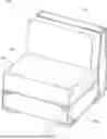
Turning now to the Figures, FIG. 1 illustrates a perspective view of a modular seating assembly 100. Modular seating assembly 100 includes a seat base 102a, a back member 104, and a cushion 106. Cushion 106 provides an end user with a seating surface 127 that can be oriented in various directions to provide an ergonomic or desired level of pitch. As illustrated, the modular seating assembly 100 is configured in a pitched configuration (e.g., where the seating surface is pitched backward toward the back member 104), as indicated by the sloping of the cushion 106 relative to the seat base 102a. Though not shown, this pitched configuration is a byproduct of a user positioning a seat pan at an angle A relative to the seat base. Angle A can represent a range of angles from 0 degrees relative to the seat base (i.e., a level seating configuration) and up to about 15 degrees relative to the seat base (i.e., a pitched seating configuration). For example, angle A can be a pitched angle ranging from about 1 degree to about 15 degrees, or about 1 degree to about 10 degrees, or about 2 degrees to about 5 degrees, or about 2.5 degrees. To provide a pitched orientation, a user may remove the cushion from the seat base and set it to the side. The user can then lift or move the seat pan away from the seat base 102a and re-engage it with the seat base 102a in a pitched seat orientation. Example views and the corresponding features that provide engagement for pitched seating configurations are described in more detail in the later figures.
Accordingly, FIG. 1 illustrates that the modular seating assemblies of the present disclosure provide an optional ergonomic adjustment without complex mechanical systems or powered components. Instead, the ability to vary the pitch of the seating surface is achieved through simple structural engagement features between the seat pan and the seat base, such as a height difference or distance between a shelf and an upper surface (see FIG. 5). This allows the user to modify the seating orientation to achieve greater comfort or accommodate different activities while maintaining the overall aesthetic and modular integrity of the furniture.
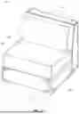
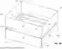
FIG. 2 illustrates a perspective view of a seat base 102a with the seat pan and cushion removed. The seat base 102a includes four side panels 108a, a central frame 110a, and a corner pillar 112a. The central frame 110a provides a central structural support member that interconnects the various side panels and corner pillars to define the overall geometry of the seat base 102a. In some embodiments, the central frame 110a can be formed from a rigid material such as wood, metal, or a composite structure, and can include mounting or coupling features that facilitate tool-free assembly with adjacent components. The central frame also has an upper surface 124 that can engage with a side, edge, or corner of a seat pan. For example, in a level configuration, a seat pan can rest or engage on the shelves 122a of the corner pillars 112a in each of the four corners of the seat base 102a. However, in a pitched configuration, two corners of the seat pan (or one side or edge) can rest or engage on the upper surface 124, which is below shelves 122a, while the remaining corners or opposing side or edge of the seat pan can rest on the remaining shelves 122a. This can cause one side of the seat pan to be raised while the opposing side is lowered.
FIG. 2 also illustrates that the four side panels 108a are coupled with at least the central frame 110a. A cross-sectional view of this engagement is shown in FIG. 5. Thus, the side panels 108a define the outer perimeter of the seat base 102a. Side panels 108a include a cover or inner cover 116. An individual inner cover 116 wraps around an individual side panel 108a to provide a fabric or similarly soft outer layer to each panel 108a (see FIG. 5). Inner cover 116 can engage with connection components 118a and 118b on an inner surface of the side panel 108a. For example, connection components 118a and 118b can be hook-and-loop material that engages or couples to the inner cover 116. Connection components 118a and 118b are disposed at or near the upper and lower edges of the inner face of the side panel 108a. The inner face of the side panel 108a is enclosed when the side panel 108a is secured to the central frame 110a, thereby protecting the connection components from external interference and reducing the likelihood of unintended disengagement. In some embodiments, inner cover 116 completely wraps around the side panel 108a, having a slot or cutout to allow for the passage of fasteners, protrusions, etc.
As shown in FIG. 2, each corner pillar 112a can include one or more shelves 122a that define discrete engagement location surfaces for a seat pan to engage. The shelf 122a provides a surface wherein a seat pan may rest or engage to establish either a level configuration or a pitched configuration. Each corner pillar 112a can also include a bottom end 120 that engages with a foot (not shown). The bottom end 120 is positioned at one end of the corner pillar, opposite the shelf 122a. An aperture 126 passes through the bottom end 120 and can selectively receive a post (such as a threaded post) of a foot. In this manner, the corner pillar 112a serves both as a load-bearing support and as an adjustment mechanism, enabling the seat pan to rest securely at multiple elevations or angles relative to the base 102a.
The seat base 102a further defines a through cavity 114 that extends vertically or laterally through the central frame 110a (i.e., from the top edge 128 of the side panel 108a to the bottom edge 130 of the side panel 108a). The through cavity 114 can serve multiple purposes, including but not limited to reducing overall material weight, allowing access to a supporting surface (e.g., a floor), and providing an internal space where electronic equipment or other items can be secured or stored. An inner surface of the central frame 110a, the top edge 128, and the bottom edge 130 thus define the dimensions of the through cavity 114.
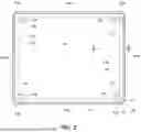
FIG. 3 illustrates a top-down facing view of seat base 102a, showing components such as the side panels 108a, central frame 110a, corner pillars 112a, through cavity 114, shelves 122a, and upper surface 124. Also shown are panel ends 142, which, when positioned adjacent to one another, define gaps 140 between neighboring panels at each corner of the seat base 102a. The gap 140 can accommodate inserts or alignment members as part of an outer cover assembly, as described in FIG. 4. These gaps 140 can also facilitate dimensional tolerance between adjoining panels, ensuring proper fit, and can receive an insert of a cover to assist in alignment (see FIG. 6A). FIG. 3 also illustrates that the upper surface 124 of the central frame 110a provides a planar interface for receiving the seat pan that extends around the entire seat base 102a. By extending around the entire seat base, the upper surface supports a plurality of pitched seat configurations (see FIGS. 15A-15D). Side panels 108a also extend along each of the four edges of the central frame 110a, and together form the perimeter structure of the seat base 102a.
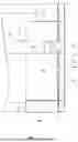
FIG. 4 illustrates an exploded view of a seat base 102a, showing the positioning between the central frame 110a, side panels 108a, and corner pillars 112a. As illustrated, two opposing side panels 108a can have a length of L3, while the remaining two opposing side panels can have a length of L4. L4 is longer than L3, thus providing a seat base 102a that is rectangular in nature. A user will appreciate this feature, as depending on which side panel 108a is oriented as the front, the user can sit in either a deep mode (a longer distance from the front of the seat to the back rest) or a wide mode (a shorter distance from the front of the seat back to the back rest while instead providing a wider seat).
FIG. 4 also shows that the central frame 110a includes a U-shaped channel 152 configured to receive a protrusion 150 extending from the inner face of each side panel 108a. Thus, the U-shaped channel 152 opens outwards and away from the through cavity 114. The protrusion 150 can be formed monolithically with the side panel 108a (for example, molded, routed, or machined as part of the side panel 108a body) or it can be an added member that is secured to an inner face 154 of the side panel 108a through fastening, adhesive bonding, or other coupling means.
When assembled, the protrusion 150 is received within the U-shaped channel 152 of the central frame 110a. Once inserted, the manufacturer fastens, adheres, or otherwise secures the protrusion 150 within the channel to create a rigid interlock between the central frame 110a and side panel 108a. The inner face 154 of each side panel 108a also abuts one or more corner pillars 112a, which provides additional structural support and helps prevent flexing, bending, or breakage of the side panels 108a when the seat base is impacted or subjected to dynamic loads.
As illustrated, the protrusion 150 has a length L1 that can be substantially similar to or shorter than a length L2, where L2 represents the distance between two corner pillars 112a positioned along the same edge of the seat base 102a. This proportional relationship provides that the protrusion of 150 fits securely between the corner pillars.
FIG. 5 illustrates a cross-sectional view of the seat base 102a, showing the engagement of a protrusion 150 within the U-shaped channel 152 of the central frame 110a. In this view, the relationship between the side panel 108a, the corner pillar 112a, and the central frame 110a is shown. Protrusion 150 extends outward from the inner face 154 of the side panel 108a and is received within the U-shaped channel 152, forming a secure connection between these components. A manufacturer can fasten, adhere, and/or otherwise secure the protrusion 150 within the U-shaped channel 152. The inner face 154 of the side panel 108a is also shown abutting the corner pillar 112a, providing additional lateral support and reinforcement of the side panel 108a.
FIG. 5 further illustrates a height H, which represents the vertical distance between the shelf 122a of the corner pillar 112a and the upper surface 124 of the central frame 110a. The height H defines the offset that produces the pitched angle (angle A, see FIG. 1) when the seat pan is re-engaged with the seat base 102a in a pitched configuration. For example, when one end of a seat pan rests higher on a shelf 122a and the opposing end of the seat pan rests on the upper surface 124, the seat pan exhibits an angled surface that corresponds to the distance or height H of the upper surface and the shelf 122a. In general, a larger height H results in a greater seating angle, while a smaller height H produces a more subtle pitch. Accordingly, this structural relationship provides a simple geometric means of manually adjusting seat pitch, allowing for multiple ergonomic configurations within the same modular seat assembly.
FIG. 5 also illustrates the aperture 126 defined by the bottom end 120 of the corner pillar 112a. As illustrated, aperture 126 is a series of through holes that allow for the passage of a post of a foot or other mountable device/element. In some embodiments, aperture 126 is a single through hole.
FIG. 6A illustrates a seat base 102a and an associated outer cover 160 according to an implementation of the present disclosure. As shown, the outer cover 160 is configured to extend around the outer surface of each side panel 108a (including outside of the inner cover 116) while leaving the through cavity 114 of the central frame 110a unobstructed. In this manner, the outer cover 160 provides an aesthetically pleasing exterior surface for the seat base 102a without obstructing functional openings or structural engagement features. As illustrated, the outer cover 160 is positioned outside of the inner covers 116, collectively creating a layered covering system that enhances both comfort and visual appearance. Similar to the inner cover 116, the outer cover 160 can be secured to connection components (such as hook-and-loop fasteners, clips, or adhesive strips) located along the inside face of the side panels 108a (see FIGS. 2, connection components 118a, and 118b). This allows the outer cover 160 to be easily installed, removed, or replaced by an end user while maintaining a taut, finished appearance. Further, this can provide protection to the connection components, as they are on the inner face, as opposed to a top or bottom surface, which may get caught when moving the seat base around.
FIG. 6A illustrates that the outer cover 160 includes one or more inserts 162, which can take the form of dowels, bundled fabric, posts, foam segments, and/or other semi-rigid members positioned to correspond with the gaps 140 defined between adjacent panel ends 142. The inserts 162 serve as alignment and positioning aids, enabling the user to properly orient and guide the outer cover 160 over and around the seat base 102a during installation. For example, a user aligns the inserts 162 with the gaps 140 at each corner of the seat base 102a. The user can then slide or guide the cover 160 over and around the seat base 102a (i.e., starting at the top edge 128 and guiding towards the bottom edge 130, or starting at the bottom edge 130 and guiding towards the top edge 128). This process causes the inserts 162 to fill or engage with the gaps 140. Once positioned, the inserts 162 can function as cushioned corner elements, smoothing transitions between adjacent side panels and providing a soft edge. The inserts 162 can be formed from semi-rigid or cushioning materials, such as foam or resilient polymer, to provide localized impact absorption while maintaining alignment of the outer cover 160 relative to the seat base 102a. In at least one embodiment, a portion (e.g., a flap) of the cover 160 folds over or around the top edge 128 and/or bottom edge 130 to secure to the inside of the side panels 108a.
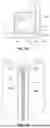
FIG. 6B illustrates a seat base 102a-1 including one or more end caps 350a and 350b that allow for the engagement of an insert 162 of an outer cover (see FIG. 6A). The seat base 102a-1 includes side panels 108a-1 and 108a-2, each having end caps 350a and 350b affixed to the ends of the respective side panels. The end caps 350a and 350b are coupled to the side panels after the side panels have been wrapped with an inner cover 116. This configuration allows the inner cover 116 to be applied around each side panel in a manner similar to wrapping a present, where the panel ends 142 may include folds, seams, or multiple layers of the inner cover 116. The end caps 350a and 350b conceal the panel end 142, thereby providing a clean and aesthetically pleasing outer appearance to the remainder of the side panel. Together, the end caps 350a and 350b can partially fill the gap 140 (see FIG. 6A) and define a slot 352 configured to receive an insert 162 of an outer cover. As shown, the slot 352 is curved, though in other implementations, the slot may be angled or sloped to correspond to the shape of the insert or desired aesthetic profile.
FIG. 6C illustrates a close-up or more detailed view of a seat base 102a-2 showing end caps 350a and 350b secured to the ends of side panels 108a-1 and 108a-2. Each end cap 350a and 350b includes one or more tabs 354 that extend inwardly toward the back or inner surface of the respective side panel, and over any applied inner cover 116. The tabs 354 can serve as anchors or attachment features that assist in fastening the end caps to the side panels, such as by adhesive, fasteners, or press-fit engagement. As illustrated, the end caps 350a and 350b extend across and conceal the entire panel end 142 of each side panel, providing a clean finished edge and continuous interface with adjacent structural components. As shown, the slot 352, defined between the end caps 350a and 350b, is continuous and extends the full height of the side panels. The slot 352 is configured to receive an insert 162 of an outer cover, and may have a curved, angled, or sloped profile to correspond to the desired contour or shape of the cover insert.
FIG. 6D illustrates another perspective view of the seat base 102a-2, showing the end caps 350a and 350b in greater detail. The figure further highlights the continuous nature of the slot 352 formed between the end caps along the height of each side panel 108a-1 and 108a-2. As shown, the slot 352 extends uniformly from the upper to the lower edges of the side panels, providing a consistent channel for receiving the insert 162 of an outer cover. The end caps 350a and 350b fully enclose the panel end 142 of the side panels, concealing any seams, folds, or material layers of the inner cover 116 to maintain a smooth and visually continuous edge appearance.
FIGS. 7-10 illustrate another embodiment of the modular seat base 102h, which is similar to and adaptable with the features of seat base 102a shown in FIGS. 2-5. Seat base 102h, however, includes a different central frame structure made from one or more L-shaped brackets 196 secured between corner pillars 112d.
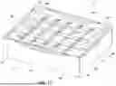
FIG. 7 illustrates a perspective view of a seat base 102h according to an implementation of the present disclosure. Similar to seat base 102a of FIG. 2, the seat base 102h includes a central frame, side panels 108d, and corner pillars 112d. The central frame is defined by a plurality of L-shaped brackets 196, joined at their ends to a plurality of corner pillars 112d. A through cavity 114 is still provided, panels 108d still include an inner cover 116, and connection components 118a and 118b are also included. Additionally, seat base 102h includes an upper surface 124 (of the L-shaped brackets 196) and a shelf 122a, which provides for either level or pitched engagement with a seat pan. FIG. 7 also shows that the bottom end 120 of the corner pillars 112d engages with a foot. Thus, while the illustrated embodiment demonstrates an alternative arrangement of internal bracing, the features provided are similar and interchangeable with those of another embodiment of the seat bases disclosed herein.
FIG. 8 illustrates a top-down facing view of the seat base 102h. As shown, the L-shaped brackets 196 extend between and couple to the corner pillars 112d, thereby defining the central frame. The arrangement of the brackets provides structural rigidity while still maintaining the open through cavity 114, which reduces weight and allows access to a supporting surface whereon the seat base 102h is mounted (e.g., the floor). The corner pillars each include the shelf 122a for engagement with a seat pan, and the upper surfaces 124 of the L-shaped brackets 196 form continuous support interfaces that extend between the pillars. Thus, even though the L-shaped brackets 196 are not a continuous or monolithic structure, the upper surface 124 is still provided along each side of the seat base 102h. Gaps 140 between adjacent panel ends 142 remain present to receive inserts or alignment members when an outer cover is installed.
FIG. 9 illustrates an exploded view of the seat base 102h. The exploded configuration shows the assembly relationship between the corner pillars 112d, L-shaped brackets 196, and side panels 108d. Each L-shaped bracket 196 provides an outer engagement surface 192 along which the side panels 108d are secured. Each side panel 108d can include a recess 151 configured to align the side panel 108d with the L-shaped brackets 196 and the corner pillars 112d. The recess 151 is a cutout or gap in the inner cover 116 to allow for direct contact of the panel to the central frame. In at least one embodiment, no recess 151 is provided by panels 108d; instead, the inner face 154 of panels 108d is substantially planar and fastens directly to engagement surface 192. The side panels 108d are fastened, bonded, or otherwise coupled to the brackets 196 and/or corner pillars 112d to form a rigid and lightweight structure. Two opposing panels 108d may have a first length L3, and the remaining two may have a second length L4, thereby enabling the seat base 102h to be oriented in either a deep or wide configuration, depending on user preference or assembly orientation.
FIG. 10 illustrates a cross-sectional view of the seat base 102h. This view illustrates the structural relationship between the L-shaped bracket 196, the corner pillar 112d, and the side panel 108d, as well as the vertical offset between the shelf 122a and the upper surface 124 that defines a height H. The height H determines the pitched angle achieved when a seat pan is re-engaged with the base in a pitched configuration. As illustrated in FIG. 10, rather than a protrusion-channel engagement, the inner face 154 of panel 108d can directly engage with engagement surface 192 of the central frame. This can allow a manufacturer to provide a simplified cover 116 that does not include a slot or opening where a protrusion resides. A manufacturer can also secure each side panel 108d to one or more corner pillars 112d to provide additional support.
FIG. 11 illustrates another embodiment of a seat base 102b according to an implementation of the present disclosure. Similar to seat base 102a, the seat base 102b includes a through cavity 114, side panels 108b, and corner pillars 112b positioned at each corner of the assembly. In this embodiment, each corner pillar 112b includes two shelves 122b, which define engagement surfaces for a seat pan, providing both a level configuration and a pitched configuration. This differs from the embodiment shown in FIG. 2, where a single shelf and the upper surface of the central frame were used to define the two engagement levels. In this embodiment, the height difference or distance between the shelves 122a and 122b can define the pitched angle provided by the seat base 102b.
As shown in FIG. 11, the central frame 110b is positioned at or near a lower edge 130 of the side panels 108b, as opposed to the central frame 110a of FIG. 2, which is positioned closer to the top edge 128. The central frame 110b is directly fastened to the side panels 108b using fasteners, adhesives, or interlocking joints (i.e., without a protrusion and channel engagement). This is similar to the way in which engagement surface 192 engages with panels 108d (see FIG. 10). The side panels 108b can likewise be fastened to both the corner pillars 112b and the central frame 110b, forming a rigid, integrated structure. Seat base 102b further includes corner plates 170, each positioned near the lower edge 130. Each corner plate 170 defines one or more apertures configured to receive a foot, a mounting post, or other accessory components such as electronic modules, a mount/bracket, and/or storage attachments. In some embodiments, the corner plate 170 may be formed integrally with the corner pillar 112b, while in other implementations it may be a separate member fastened to the pillar or frame.
FIG. 12 illustrates another embodiment of a seat base 102c according to an implementation of the present disclosure. The seat base 102c includes side panels 108c-1 and 108c-2, a central frame 110c, and a through cavity 114 that extends through the seat base to reduce weight and provide a usable inner volume. The seat base 102c also includes one or more corner members 180a, which are similar in form and function to the previously described corner pillars 112a and 112b, but differ in that the corner members 180a do not extend downward to the bottom edge of the base and do not connect directly or engage with the central frame 110c. Instead, each corner member 180b is secured to one or more of the side panels 108c-1 and 108c-2 and provides shelves 122a and 122b for receiving and supporting a seat pan in either a level or pitched configuration.
In this embodiment, the manufacturer assembles the seat base 102c by sliding a protrusion of the side panel 108c-1 into a T-shaped channel (see FIG. 13B) of the central frame 110c in a first direction D1. Once 108c-1 is properly seated within the channel, the side panel 108c-2 is slid into engagement with the same or an opposing T-shaped channel of the central frame 110c in a second direction D2. This sequential engagement process allows the manufacturer to lock the panels in place, as the edges of one adjacent side panel can prevent another side panel from sliding out once fully inserted. After the side panels 108c-1 and 108c-2 are engaged with the central frame 110c, the corner members 180b can be installed or fastened along the adjoining panel edges to complete the strengthening of the corners of the seat base 102c. Thus, corner members not only provide shelves 122a and 122b but also reinforce the corner joints between side panels, improving stability and preventing separation under load.
FIGS. 13A through 13D illustrate various embodiments of central frames, including central frames 110a, 110c, and 110d and their corresponding configurations for coupling with side panels of the modular seating assemblies. Each central frame defines a unique engagement geometry that allows the manufacturer to select an assembly method best suited to the desired production process, material set, or performance requirements.
FIG. 13A illustrates an embodiment of a central frame 110a having a U-shaped channel 152 configured to receive a corresponding protrusion from a side panel, as previously described with respect to FIG. 4. The central frame 110a can be formed as a monolithic member, for example, through extrusion, molding, or machining, or it can be assembled from multiple components (e.g., each edge of the channel can be welded, fastened, or otherwise secured together). FIG. 13B illustrates an embodiment of a central frame 110c including a T-shaped channel 190. The T-shaped channel 190 is configured to allow side panels to slide into engagement with the central frame along the direction of the channel rather than simply being inserted or dropped into place. The sliding engagement provides retention of the side panels during assembly.
FIG. 13C illustrates another embodiment of a central frame 110d, which includes a series of L-shaped brackets 196 defining outer engagement surfaces 192 (or first edge). The L-shaped brackets 196 are secured at their ends to the corner pillars 112d, thereby forming a rigid interconnected frame. In this configuration, the central frame 110d functions as a hybrid structural system, combining brackets with corner pillars (as opposed to embodiments where the central frame forms a continuous ring-like member, which is then secured to a corner pillar). FIG. 13C also illustrates a foot 194 that is threadingly engaged with one of the corner pillars 112d.
FIG. 13D illustrates still another embodiment of a central frame 110e. The central frame 110e includes one or more geometric members 191 extending between corner pillars 112f. The geometric members 191 are similar to the L-shaped members described in previous figures and provide structural connection and rigidity across the central frame 110e. Each geometric member 191 includes a series of apertures 197 configured to receive fasteners for securing side panels or other modular components to the frame. Additional apertures 189 are provided along the members 191 (such as along the lower edge of the geometric member 191) to allow a manufacturer or end user to attach various accessories or attachments, such as storage trays, electronics housings, power outlets, brackets, or other components, as shown, for example, in FIGS. 18 and 19.
FIGS. 14A through 14D-2 illustrate various embodiments of seat pan constructions according to implementations of the present disclosure. Each embodiment demonstrates an approach to achieving structural support and user comfort, while maintaining compatibility with the modular seat bases described above (i.e., having the structural support and configuration to allow for pitched seating). The seat pans can be manufactured from a variety of materials, including but not limited to wood, metal, or composite structures, and can incorporate suspension means to provide a suspended seating surface 208.
FIG. 14A illustrates an embodiment of a seat pan 200a constructed from one or more side members 204 that are secured together to define the perimeter of the seat pan 200a. At each corner, the seat pan 200a includes corner members 206, which provide reinforcement and structural stability at the junctions between adjoining side members 204. The inclusion of corner members 206 helps distribute load evenly across the seat pan and enhances resistance to twisting or flexing during use. Seat pan 200a also includes two forms of suspension means, designated as 202a and 202b, which extend perpendicular to one another between opposing side members 204. The first suspension means 202a comprises fabric straps that may be elastic or tensioned to provide a soft, resilient support surface for a seat cushion or occupant. The second suspension means 202b includes metal S-springs, which provide a complementary form of suspension with higher load capacity and responsive rebound. Together, suspension means 202a and 202b create a bi-directional suspension network that distributes weight evenly across the seat pan 200a.
FIG. 14B illustrates another embodiment of a seat pan 200b, which is formed as a monolithic metal, wood, or composite frame providing both structural support and an integrated seating surface 208. The monolithic construction can be achieved through stamping, molding, or casting processes, resulting in a rigid yet lightweight structure suitable for high-strength applications. Seat pan 200b further includes multiple suspension means 202c, 202d, and 202e, arranged to provide bi-directional suspension across the seating surface 208. The suspension means 202c are springs, while the suspension means 202d are rods connected thereto. Suspension means 202d extends laterally across the seat pan and serves as a connection element between springs and suspension means 202e. The suspension means 202e includes flexible (or non-flexible) strands or cables, which extend in a direction generally perpendicular to the rods (suspension means 202d) they are coupled directly to. A plurality of suspension means 202e are used to create a bi-directional support network. Together, the springs, rods, and strands form a dynamic suspension system that distributes the load evenly across the seating surface 208.
The seat pan 200b also includes corner structures 210 positioned at each corner of the frame. These corner structures 210 are shaped and configured to engage with the shelves (e.g., shelves 122a 122b) or upper surfaces (e.g., upper surface 124) of the seat bases described elsewhere in the present disclosure. Each corner structure 210 includes an engagement tab 212, which is sized to fit securely into a corresponding shelf on a seat base.
FIG. 14C illustrates another embodiment of a seat pan 200c that provides a seating surface 208 and is designed as a lightweight modular construction. The seat pan 200c comprises multiple beams 220, corner couplers 222, and a suspension means 224 extending between the beams. The suspension means 224 can be formed from a fabric or mesh material that possesses elastic or tensioned suspension qualities, allowing it to flex and conform under load while maintaining a seating surface 208 whereon a seat cushion is supported. The suspension means 224 includes a series of sleeves 226 positioned along its perimeter. During assembly, a manufacturer or user can insert each beam 220 through a corresponding sleeve 226 and then secure a corner coupler 222 at each end of the beam 220. This process can be performed for each edge of the suspension means 224, or for each individual sleeve section. The process of securing all the beam 220 into the corner couplers 222 results in the suspension means 224 being pulled tight, creating a uniformly tensioned seating surface 208. This configuration offers a lightweight yet durable solution that minimizes the amount of rigid material (i.e., corner and beams) while maintaining sufficient structural integrity to support the user's weight during normal use.
FIG. 14D-1 illustrates still another embodiment of a seat pan 200d according to an implementation of the present disclosure. The seat pan 200d is configured to provide a flat or level ride, meaning a user does not sink or bunch toward the center of the seat pan when seated. The seat pan 200d includes a non-stretching central region 211 and a plurality of stretching regions 215 arranged around the periphery of the central region 211. Seat pan 200d also includes corner couplers 221 at each corner of the beam frame 205, which are two-part components that clamp around both the suspension material and the beam to secure the seat pan under tension. Together, the central region 211 and stretching regions 215 define a suspension assembly that is tensioned across an underlying beam frame 205 (see FIG. 14D-2).
The central region 211 is formed from a non-stretch or low-stretch material, such as a woven fabric or reinforced textile, while stretching regions 215 are composed of materials configured to elongate in a specific direction (such as directions D3, D4, D5, and D6). Thus, each stretching region is designed to stretch only in a direction that is perpendicular to the adjacent edge of the seat pan. The outer circumference 213 of the central region 211 is shaped (curved) to counteract the deflection caused by the stretching regions 215, such that when a user sits within the central region, the surrounding various stretching regions 215 deflect to maintain a generally level seating plane rather than forming a deep depression or divot right below the user's posterior.
FIG. 14D-2 illustrates a partially disassembled view of the seat pan 200d shown in FIG. 14D-1. The seat pan 200d includes a central region 211 and stretching regions 215 as described previously. The seat pan 200d further includes a set of panels 217a, 217b, 219a, and 219b that together form the peripheral connection structure for tensioning the suspension means to the beam frame. Panels 217a and 217b are longer than panels 219a and 219b, and each longer panel 217a and 217b connects at its ends to a corresponding shorter panel (i.e., 217a to 219a and 217b to 219b). Each of the panels 217a, 217b, 219a, and 219b includes a J-clip or similar connector 223 along its edge. During assembly, the longer panels 217a and 217b wrap around the underside of the seat pan and couple to the shorter panels 219a and 219b via the connectors 223 (i.e., elastically deforming or stretching the panels around the central frame). This coupling process draws the stretching regions 215 taut, thereby tensioning the suspension material and enabling the seat pan 200d to act as a stretched suspension surface when secured to the underlying beam frame. Additionally, corner coupler 221 is shown as a two-part component wherein a first part and a second part are on opposite sides of the seat pan. Together, the two parts clamp around both the suspension material and the beam to secure the seat pan under tension.
FIG. 15A through 15D illustrate various pitched configurations or pitched orientations 250a, 250b, 250c, and 250d. Each pitched orientation includes altering which side of the seat pan engages with the upper surface or the shelf of the seat base. Though not illustrated, a level orientation or level configuration includes a seat pan engaging with either only the selves at each corner (of the seat pan) or only the upper surface at each edge (of the seat pan). Though the terms “front face” and “left face” are used to describe the following orientation, these are merely illustrative, as any side of the seat bases disclosed herein can act as a front face or left face, depending on how a user orients the seat base.
FIG. 15A illustrates a forward pitched orientation 250a of the seat pan 200d relative to the seat base 102a. In this configuration, the seat pan 200d is pitched toward the front face 252. The front side of the seat pan 200d (i.e., the side adjacent to the front face 252) is positioned on the shelves of the upper surface 124 of the central frame, while the rear side of the seat pan 200d (i.e., the side opposite front face 252) rests on the shelves 122a. This configuration positions the seating surface 208 at a forward slope, providing an active seating angle.
FIG. 15B illustrates a rearward pitched orientation 250b of the seat pan 200d relative to the seat base 102a. In this configuration, the seat pan 200d is pitched toward the back face (i.e., opposite front face 252). The front side of the seat pan 200d (i.e., the side adjacent to the front face 252) is positioned on the shelves of the corner pillars (hidden from view), while the rear side of the seat pan 200d (i.e., the side opposite front face 252) rests on the upper surface 124 of the central frame 110a. This configuration positions the seating surface 208 at a rearward slope, providing a reclined seating angle that can enhance comfort and relaxation for lounging or casual seating applications.
FIG. 15C illustrates a rightward pitched orientation 250c of the seat pan 200d relative to the seat base 102a. Here, the seat pan 200d is pitched toward the right side (i.e., the side opposite the left face 254) of the seat base 102a. The left side of the seat pan 200d (i.e., the side nearest the left face 254) is supported by the shelves of the corner pillars, while the right side (i.e., the side opposite the left face 254) rests on the upper surface 124 of the central frame 110a. This orientation produces a lateral slope across the seating surface 208 from left (high) to right (low), enabling ergonomic adjustment for asymmetrical seating positions or for use in modular arrangements where adjoining seats are angled differently. As previously described with respect to the wide and deep seating modes, when the left face 254 is oriented as the front face of the seat base 102a, this same configuration instead allows for a rearward pitched orientation in that alternate orientation, further demonstrating the versatility and adaptability of the disclosed seating assemblies.
FIG. 15D illustrates a leftward pitched orientation 250d of the seat pan 200d relative to the seat base 102a, which represents the opposite configuration of the orientation shown in FIG. 15C. In this embodiment, the seat pan 200d is pitched toward the left side (i.e., the side nearest the left face 254) of the seat base 102a. The right side of the seat pan 200d (i.e., the side opposite the left face 254) is supported by the shelves of the corner pillars, while the left side (i.e., the side nearest the left face 254) rests on the upper surface of the central frame. This arrangement produces a lateral slope across the seating surface 208 from right (high) to left (low), thereby complementing the rightward pitched configuration of FIG. 15C. Similar to the previously described relationship between the wide and deep modes, if the left face 254 of the seat base 102a is oriented as the front face, the configuration illustrated in FIG. 15D can provide a forward pitched orientation in that orientation, further demonstrating the multi-directional ergonomic adjustability and modular versatility of the present disclosure.
FIG. 16 illustrates a cross-sectional view of the seat base 102d and seat pan 200d corresponding to the forward pitched orientation 250a shown in FIG. 15A. In this view, the front side of the seat pan 200d (i.e., the side nearest the front face 252 of the seat base 102a) is shown resting on the upper surface 124 of an L-shaped bracket 196. Conversely, the rear side of the seat pan 200d (i.e., the side nearest the rear face, which is opposite the front face 252) is shown supported by the shelf 122a of the corner pillar 112d. This differential in support height between the upper surface 124 and the shelf 122a establishes the forward pitched angle of the seating surface 208. As illustrated, the front of the seat pan 200d is positioned lower than the rear, producing a forward-leaning ergonomic posture that encourages active sitting while maintaining stable engagement between the seat pan and the base.
FIG. 17 illustrates an embodiment of a seat base 102e having a soft edge mechanism. The seat base 102e includes side panels 108e, a seat pan 200e, corner members 180b, and a suspension member 262. The corner members 180b are formed as block-like structures that are fastened between two adjacent side panels 108d, thereby reinforcing the corners of the base and providing a shelf for the seat pan 200e to engage. In the illustrated embodiment, the seat pan 200e is shown in a pitched configuration, demonstrating the same variable seating orientation capability described in connection with FIGS. 15A-15D.
Each side panel 108e includes a recess 260 formed along its top edge 128. In the illustrated example, recess 260 has a curved profile; however, in other embodiments, the recess may be angular, squared, or faceted, depending on design preference or material selection. At either end of the recess 260 are notches 266, each configured to receive a prong 264 of the suspension member 262. The suspension member 262 is illustrated as an elongated, linear element having elastic or spring-like properties that bias it toward a straight or neutral state. When both prongs 264 are engaged within their respective notches 266, the suspension member 262 is positioned across or over the recess 260, allowing it to flex into the recess 260 when weight is applied. This configuration allows the suspension member 262 to function as a soft-edge feature for the upper perimeter of the seat base 102e. A rigid upper edge of a side panel can sometimes be felt sharply by a user when seated near the edge of the furniture, creating a perceptible pressure point. By contrast, the spring-like nature of the suspension member 262 allows the top edge to flex slightly under localized load, softening the tactile feel and reducing edge perception when a user sits near or leans against that region. This creates a more comfortable and forgiving seating experience while preserving the clean structural form of the modular base. The soft-edge feature, therefore, enhances the overall ergonomic performance and perceived quality of the seating assembly without adding bulk or mechanical complexity.
In at least one embodiment, suspension member 262 is not an elongated and linear member but is instead a coil, S-shaped, or similar style spring member that spans across the recess 260. Similarly, a woven or fabric elastic member may also be used.
FIGS. 18 and 19 illustrate an embodiment of a seat base 102f configured to accommodate mounting components and internal devices within the through cavity 114. These figures demonstrate how the modular seating assemblies of the present disclosure can integrate functional features, such as electronics, speakers, storage compartments, or other accessories, while still retaining the features previously discussed.
FIG. 18 illustrates a top-down view of the seat base 102f, showing the through cavity 114 housing a device 282. The device 282 may represent any accessory or functional component suitable for integration within the furniture base, such as an electronic control unit, a speaker, a lighting module, or a personal storage compartment. The device 282 is supported by mounts 280a and 280b, which are configured to engage with one or more bottom ends 120 of the corner pillars 112e. Once positioned, the mounts 280a and 280b can be secured to the device 282 using fasteners or thumb screws 284, allowing for installation or removal by either the manufacturer or the end user. This configuration offers a modular approach to incorporating optional features without modifying the core seat base structure. In at least one embodiment, a single mount that engages all four of the bottom ends is used.
FIG. 19 provides a perspective view of the same seat base 102f, with two side panels and their associated L-shaped brackets removed to illustrate the internal configuration and engagement between components. As shown, a foot 194 includes an upwardly extending post 195 that passes through the apertures (e.g., aperture 126) defined by the bottom ends 120 of the corner pillars 112e and the mount 280a. A top nut or fastener can then be applied to secure all components together in a stacked assembly, coupling the foot 194, mount 280a, and corner pillar 112e into a unified structure. This arrangement not only provides support and stability for the seating assembly but also enables convenient installation and removal of functional devices positioned within the through cavity 114. Additionally, post 195 can include a spring-loaded detent 199 that allows a user to couple the foot 194 to the bottom end 120 by simply pushing the post into the aperture 126. This advantageously provides a quick connect-and-release mechanism that does not require screwing or twisting of the foot 194 or post 195, which can take a longer period of time to complete. The detent 199 can engage with a connection component of the bottom end 120, for example, the edge of aperture 126 to prevent foot 194 from falling out.
FIGS. 20A and 20B illustrate embodiments of rotatable shoes configured for use with the modular seating assemblies of the present disclosure. These components allow multiple seat bases to be mechanically coupled or decoupled from one another in a simple and repeatable manner, allowing users or manufacturers to connect seating modules into larger assemblies such as couches or sectionals. FIG. 20A illustrates a seat base 102g equipped with rotatable shoes 300a-300c, which represent the same shoe shown in three different rotational positions. Each rotatable shoe 300a-300c is mounted to a support 308 positioned near a corner of the seat base 102g. In some embodiments, the support 308 is formed as part of the bottom end 120 of the seat base or the corner pillar, as shown in previous embodiments. Each rotatable shoe 300a-300c pivots about a pivot point 304, allowing the shoe to rotate between various deployed and stowed configurations. Support 308 (or, in some embodiments, the rotatable shoe 300a) also includes a spring-loaded detent 306, which exerts a resistive force on the rotatable shoe 300a-300c to prevent unintended movement and maintain the shoe in a selected position during use. Each shoe 300a-300c is a solid block or section of material wherein the cups 302 are through holes or cut out into the block or section of material.
FIG. 20A also illustrates that shoe 300a is rotated outward such that three cups 302 extend from beneath the seat base 102g, ready to receive feet from a foot from an adjacent seat base for coupling. Shoe 300b is shown in an intermediate position, where two cups 302 project outward, while the remaining cup is retained beneath the seat base 102g base. Shoe 300c is rotated fully inward, storing all cups 302 beneath the seat base 102g for situations where interconnection is not required or when the furniture is used as a standalone unit. The cups 302 are sized and shaped to receive and retain a corresponding foot or post from an adjacent seat base, thereby enabling multiple units to be aligned, stabilized, and joined together in a secure yet reversible fashion. This configuration provides users with a flexible connection mechanism that maintains the modularity and adaptability central to the present seating system.
FIG. 20B illustrates another embodiment of the rotatable shoe system, shown as rotatable shoes 310a-310c, which function similarly to the rotatable shoes 300a-300c described in FIG. 20A, but utilize a different coupling interface. Each rotatable shoe 310a-310c is mounted to a support 308 near a corner of the seat base 102i and is configured to rotate about a pivot point 304. As in the previous embodiment, the support 308 may form part of a bottom end 120 or structural member of the seat base and can include a spring-loaded detent 306 that provides a resistive force to maintain the rotatable shoe 310a-310c in a desired position and prevent unwanted rotation during use. In this embodiment, however, each rotatable shoe 310a-310c includes one or more rings 312 instead of cups. The rings 312 (each defining an aperture) are designed to receive and retain a post or dowel extending from the foot of an adjacent seat base. Shoe 310a illustrates a fully deployed position, shoe 310b represents an intermediate configuration (i.e., where two of the rings 312 extend outward), and shoe 310c illustrates a fully stowed position (i.e., where all rings 312 are positioned beneath the seat base).
FIGS. 21A through 21D illustrate a process including acts 330a-330d of unpacking a shipped modular furniture assembly according to an implementation of the present disclosure. These figures demonstrate how the modular furniture assembly can be efficiently packaged, shipped, and unpacked while minimizing waste, reducing the number of boxes required, and protecting all components during transport. By utilizing the through cavity of the seat base as a storage compartment, a manufacturer can consolidate multiple furniture components (such as seat pans, panels, and accessories) into a single, compact package, simplifying logistics and reducing shipping costs.
FIG. 21A illustrates act 330a, in which a user unboxes the seat base 102j and the seat pan 200f that has been secured to the seat base 102j. In the illustrated configuration, the seat pan 200f is wrapped with one or more straps 332, which hold the seat pan and associated components together during shipment. The straps 332 maintain the assembly in a compact and stable arrangement, protecting the parts from shifting or damage while in transit. FIG. 21B illustrates act 330b, in which the user lifts and flips the seat pan 200f to access the components 334 secured beneath it by the straps 332. The components 334 may include, without limitation, side panels, corner members, fasteners, tools, cushions, covers, or other accessories used for assembling or customizing the modular seating system. The straps 332 maintain all components together as a single package, simplifying inventory and reducing the risk of lost parts during unpacking.
FIG. 21C illustrates act 330c, in which the user rests the seat base 102j and the components 334 on a surface such that the seat pan 200f is below the components 334. In this orientation, the various components are accessible and can be removed or organized as desired. FIG. 21D illustrates act 330d, in which the user removes a rod 336 from its engagement with the straps 332. In the packaged configuration, the straps 332 are looped around the seat pan 200f and components 334 and locked in place by the rod 336, which prevents the straps from loosening during shipment. Upon removal of the rod 336, the straps 332 are released, thereby freeing the seat pan and all stored components 334. This packaging method allows the manufacturer to store many, if not all, of the necessary accessories and assembly parts within the through cavity of the seat base 102j, enabling the entire furniture system to be shipped in a single, consolidated package. This approach reduces packaging material, minimizes the number of boxes required, and provides effective cost savings in shipping and handling while maintaining a compact and user-friendly unboxing experience.
It will also be appreciated that embodiments described herein can also include properties and/or features (e.g., ingredients, components, members, elements, parts, and/or portions) described in one or more separate embodiments and are not necessarily limited strictly to the features expressly described for that particular embodiment. Accordingly, the various features of a given embodiment can be combined with and/or incorporated into other embodiments of the present disclosure. Thus, disclosure of certain features relative to a specific embodiment of the present disclosure should not be construed as limiting the application or inclusion of said features to the specific embodiment. Rather, it will be appreciated that other embodiments can also include such features.
A user having ordinary skill in the art should realize, in view of the present disclosure, that equivalent constructions do not depart from the spirit and scope of the present disclosure, and that various changes, substitutions, and alterations can be made to embodiments disclosed herein without departing from the spirit and scope of the present disclosure. Equivalent constructions, including functional “means-plus-function” clauses are intended to cover the structures described herein as performing the recited function, including both structural equivalents that operate in the same manner, and equivalent structures that provide the same function. It is the express intention of the applicant not to invoke means-plus-function or other functional claiming for any claim except for those in which the words ‘means for’ appear together with an associated function. Each addition, deletion, and modification to the embodiments that falls within the meaning and scope of the claims is to be embraced by the claims.
Claims
What is claimed is:1. A modular seating assembly configured for providing level or pitched seating, the modular seating assembly comprising:
a seat base; and
a seat pan configured to provide a seating surface in: (i) a level configuration that is substantially parallel to a support surface on which the seat base is mounted; or (ii) a pitched configuration in which the seating surface is positioned at an angle relative to the support surface on which the seat base is mounted, wherein:
a user can selectively mount the seat pan in the level configuration or the pitched configuration.
2. The modular seating assembly of claim 1, wherein the seat pan can be pitched in at least two directions relative to the seat base, or at least three directions relative to the seat base, or at least four directions relative to the seat base.
3. The modular seating assembly of claim 1, wherein the modular seating assembly is configured such that the user can selectively:
(i) level the seat pan by separating the seat pan from the seat base and reengaging the seat pan with the seat base in the level configuration; and
(ii) pitch the seat pan by separating the seat pan from the seat base and reengaging the seat pan with the base in the pitched configuration.
4. The modular seating assembly of claim 1, wherein the seat pan can be separated from the seat base without the use of any tools.
5. The modular seating assembly of claim 1, wherein the seat pan comprises bi-directional suspension means.
6. The modular seating assembly of claim 1, wherein the pitched configuration is a first pitched configuration, and the seat base is configured to provide additional pitched configurations.
7. The modular seating assembly of claim 1, wherein the pitched configuration is configured to angle the seating surface by at least about 1 degree relative to a surface on which the seat base is mounted.
8. A modular seating assembly configured for providing level or pitched seating, the modular seating assembly comprising:
a seat base, the seat base comprising:
a central frame, wherein the central frame has an upper surface;
a side panel, wherein the side panel is secured to the central frame; and
a corner pillar, wherein the corner pillar comprises a shelf; and
a seat pan configured to provide a seating surface, in: (i) a level configuration that is substantially parallel to a support surface on which the seat base is mounted; or (ii) a pitched configuration in which the seating surface is positioned at an angle relative to the support surface on which the seat base is mounted, wherein:
when in the pitched configuration, the seat pan engages both the shelf and the upper surface.
9. The modular seating assembly of claim 8, wherein the shelf is positioned closer to a top edge of the side panel than the upper surface.
10. The modular seating assembly of claim 8, wherein a distance between the shelf and the upper surface defines a pitched angle of the pitched configuration.
11. The modular seating assembly of claim 8, wherein the corner pillar comprises a second shelf.
12. The modular seating assembly of claim 8, wherein the central frame defines a through cavity configured to provide a user access to a surface whereon the seat base is mounted.
13. The modular seating assembly of claim 8, wherein a bottom end of the corner pillar is configured to receive a foot.
14. A modular seating assembly configured for providing pitched seating comprising:
a seat base, the seat base comprising:
a central frame having a first edge;
a side panel, the side panel secured to the first edge; and
a corner pillar, the corner pillar secured to a portion of the first edge;
a seat pan configured to provide a seating surface in either a level configuration or a pitched configuration; and
an outer cover configured to wrap around the seat base, the outer cover comprising an insert, wherein the insert is configured to be positioned at a first end of the side panel when the outer cover is installed around the seat base.
15. The modular seating assembly of claim 14, wherein the side panel comprises an inner cover layer configured to cover an outer face and an inner face of the side panel.
16. The modular seating assembly of claim 14, wherein the seat base comprises a second side panel and the insert is configured to fill a gap defined between the first end of the side panel and a first end of the second side panel.
17. The modular seating assembly of claim 14, wherein the outer cover is configured to be selectively secured to a top edge and a bottom edge of the side panel.
18. The modular seating assembly of claim 14, wherein the side panel secured to the first edge through a protrusion that extends away from an inner face of the side panel, and wherein the protrusion engages with a U-shaped channel of the central frame.
19. The modular seating assembly of claim 14, wherein a bottom end of the corner pillar is configured to receive a foot.
20. The modular seating assembly of claim 14, wherein the outer cover comprises at least four inserts, wherein each insert is configured to align the outer cover with the seat base.
21. The modular seating assembly of claim 1, wherein the pitched configuration is configured to angle the seating surface by at least about 1 degree to about 15 degrees, or about 1 degree to about 10 degrees, or about 2 degrees to about 5 degrees, or about 2.5 degrees relative to a surface on which the seat base is mounted.
22. The modular seating assembly of claim 8, wherein the central frame defines an aperture for securing an accessory within the seat base.
23. The modular seating assembly of claim 8, wherein the seat base is configured to couple to one or more additional seat bases to form a couch.
24. The modular seating assembly of claim 13, wherein the foot comprises a post having a spring-loaded detent, and the spring-loaded detent secures the foot to a bottom edge of the corner pillar.
25. A seat pan for use in a modular seating assembly, the seat pan comprising:
a central frame;
a suspension means, the suspension means comprising:
a non-stretching central region,
a first stretching region that extends outward from the non-stretching central region, and
a second stretching region that extends outward from the non-stretching central region in a direction opposite the first stretching region; and
a corner coupler, wherein:
the first stretching region and the second stretching region each elastically deform around the central frame to couple the suspension means to the central frame, and
the corner coupler secures the suspension means to the central frame at a corner of the central frame.
26. A modular seating assembly configured for providing pitched seating comprising:
a seat base, the seat base comprising:
a first side panel, and
a second side panel positioned perpendicular to the first side panel, wherein an end of the first side panel and an end of the second side panel define a gap; and
a removable outer cover, wherein the removable outer cover comprises an insert, wherein the insert is configured to be positioned within the gap, and wherein the insert provides a soft corner to the seat base.
27. The modular seating assembly of claim 26, further comprising a first end cap positioned at the end of the first side panel and a second end cap positioned at the end of the second side panel, wherein the first end cap and the second end cap define the gap.
Images & Drawings included:


Sources:
- United States Patent and Trademark Office - verify current appl. status at the USPTO↗
Similar patent applications:
- » 20260145586
MODULAR SEAT ASSEMBLY FOR A PASSENGER VEHICLE, AND PASSENGER VEHICLE COMPRISING SUCH MODULAR SEAT ASSEMBLY - » 20240341486
MODULAR SEATING ASSEMBLY AND METHOD OF ASSEMBLY THEREOF - » 17128319
Modular seating assembly - » 20220354261
Modular seat assembly and method of assembly thereof - » 13136044
Portable modular seating assembly - » 20060290180
Modular seat assembly and method of installation thereof - » 20200189430
Modular seating assembly - » 20130082504
MODULAR SEAT ASSEMBLY - » 20120319449
Modular seat assembly for a vehicle - » 20240415290
MODULAR SEATING ASSEMBLY AND METHOD OF ASSEMBLY THEREOF
Recent applications in this class:
- » 20120018607 2012-01-26
Molded load bearing surface and method of manufacture - » 20100243856 2010-09-30
Load bearing surface