VACUUM ASSEMBLY
US20260165545A1
2026-06-18
19/417,731
2025-12-12
Smart Summary: A vacuum assembly has a main body that holds different parts. It includes a blower that helps move air and has a motor that works along a specific path. There is an inlet where dirt and dust enter, and a collection container that gathers this debris. A filter is also included to clean the air before it goes back out, and it is positioned differently from the blower. The design makes sure that the blower and filter work well together while being arranged in a unique way. 🚀 TL;DR
Abstract:
A vacuum assembly including a body, a blower assembly including a blower motor defining a first blower axis, an inlet, a collection container in fluid communication with both the blower assembly and the inlet, and a filter in fluid communication with the blower assembly. Where the filter defines a first filter axis, and where the first filter axis is parallel to and offset from the first blower axis.
Inventors:
- David C. Bell 2 🇺🇸 Milwaukee, WI, United States
- Victor G. Cinq-Mars 3 🇺🇸 Milwaukee, WI, United States
- Andrew P. Heffner 2 🇺🇸 Waukesha, WI, United States
Applicant:
Interested in similar patents?
Get notified when new applications in this technology area are published.
Classification:
A47L9/127 » CPC main
Details or accessories of suction cleaners, e.g. mechanical means for controlling the suction or for effecting pulsating action; Storing devices specially adapted to suction cleaners or parts thereof; Carrying-vehicles specially adapted for suction cleaners; Filters ; Dust separators; Dust removal; Automatic exchange of filters; Dry filters tube- or sleeve-shaped
A47L5/362 » CPC further
Structural features of suction cleaners with power-driven air-pumps or air-compressors, e.g. driven by motor vehicle engine vacuum with rotary fans; Suction cleaners with hose between nozzle and casing; Suction cleaners for fixing on staircases; Suction cleaners for carrying on the back of the horizontal type, e.g. canister or sledge type
A47L7/0023 » CPC further
Suction cleaners adapted for additional purposes ; Tables with suction openings for cleaning purposes; Containers for cleaning articles by suction; Suction cleaners adapted to cleaning of brushes; Suction cleaners adapted to taking-up liquids; Suction cleaners adapted to take up liquids, e.g. wet or dry vacuum cleaners Recovery tanks
A47L9/102 » CPC further
Details or accessories of suction cleaners, e.g. mechanical means for controlling the suction or for effecting pulsating action; Storing devices specially adapted to suction cleaners or parts thereof; Carrying-vehicles specially adapted for suction cleaners; Filters ; Dust separators; Dust removal; Automatic exchange of filters Dust separators
A47L9/12 IPC
Details or accessories of suction cleaners, e.g. mechanical means for controlling the suction or for effecting pulsating action; Storing devices specially adapted to suction cleaners or parts thereof; Carrying-vehicles specially adapted for suction cleaners; Filters ; Dust separators; Dust removal; Automatic exchange of filters Dry filters
A47L5/36 IPC
Structural features of suction cleaners with power-driven air-pumps or air-compressors, e.g. driven by motor vehicle engine vacuum with rotary fans Suction cleaners with hose between nozzle and casing; Suction cleaners for fixing on staircases; Suction cleaners for carrying on the back
A47L7/00 IPC
Suction cleaners adapted for additional purposes ; Tables with suction openings for cleaning purposes; Containers for cleaning articles by suction; Suction cleaners adapted to cleaning of brushes; Suction cleaners adapted to taking-up liquids
A47L9/10 IPC
Details or accessories of suction cleaners, e.g. mechanical means for controlling the suction or for effecting pulsating action; Storing devices specially adapted to suction cleaners or parts thereof; Carrying-vehicles specially adapted for suction cleaners Filters ; Dust separators; Dust removal; Automatic exchange of filters
Description
RELATED APPLICATIONS
This application claims priority to U.S. Provisional Application No. 63/733,314, filed on Dec. 12, 2024. The entire contents of which is hereby incorporated by reference.
FIELD
The present disclosure relates generally to a vacuum assembly and specifically to a vacuum assembly with a unique filter and blower assembly layout.
BACKGROUND
Wet/dry vacuum cleaners can be used to collect both wet and dry debris including liquids.
SUMMARY
In one aspect, a vacuum assembly including, a body; a blower assembly, where the blower assembly includes a blower motor defining a first blower axis, an inlet; a collection container in fluid communication with both the blower assembly and the inlet, and a filter in fluid communication with the blower assembly, where the filter defines a first filter axis, and where the first filter axis is parallel to and offset from the first blower axis.
Alternatively or additionally, in any combination, where the filter is substantially cylindrical in shape.
Alternatively or additionally, in any combination, where the filter includes an outlet port having a first cross-sectional shape, where the first filter axis is normal to the first cross-sectional shape of the outlet port.
Alternatively or additionally, in any combination, where the collection container is removably couplable to the body.
Alternatively or additionally, in any combination, where the filter is at least partially positioned within the collection container when the collection container is coupled to the body.
Alternatively or additionally, in any combination, where the body defines an internal volume, and where the blower assembly is at least partially positioned within the internal volume.
In another aspect, a vacuum assembly including, a body, a blower assembly, where the blower assembly includes an impeller defining a first blower axis, an inlet, a collection container in fluid communication with both the blower assembly and the inlet, and a filter in fluid communication with the blower assembly, where the filter defines a first filter axis, and where the first filter axis is parallel to and offset from the first blower axis.
Alternatively or additionally, in any combination, where the filter is substantially cylindrical in shape.
Alternatively or additionally, in any combination, where the blower assembly and the inlet are coupled to the body.
Alternatively or additionally, in any combination, where the collection container is removably coupled to the body.
In another aspect, a vacuum assembly including, a body, a blower assembly, where the blower assembly includes a blower motor defining a first blower axis, an inlet, a collection container in fluid communication with both the blower assembly and the inlet, and a filter in fluid communication with the blower assembly, where the filter is positioned so that a reference plane oriented perpendicular to the first blower axis will pass through both the blower assembly and the filter simultaneously.
Alternatively or additionally, in any combination, where the blower assembly further includes an impeller.
Alternatively or additionally, in any combination, where the reference plane passes through both the blower motor and the filter simultaneously.
Alternatively or additionally, in any combination, where the filter includes filtering material, and where the reference plane passes through both the blower motor and the filtering material simultaneously.
Alternatively or additionally, in any combination, where the collection container is releasably couplable to the body along a first connection axis, and where the first blower axis is perpendicular to the first connection axis.
Alternatively or additionally, in any combination, where the filter is at least partially positioned within the collection container.
Alternatively or additionally, in any combination, further including a vacuum tube extending between and in fluid communication with both the blower assembly and the filter.
BRIEF DESCRIPTION OF THE DRAWINGS
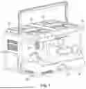
FIG. 1 is a top perspective view of the vacuum assembly of the present invention.
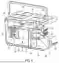
FIG. 2 is a bottom perspective view of the vacuum assembly of FIG. 1.
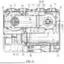
FIG. 3 is another top perspective view of the vacuum assembly of FIG. 1.
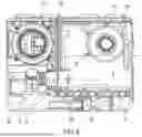
FIG. 4 is a section view taken along line 4-4 of FIG. 3.
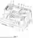
FIG. 5 is a perspective view of the section view of FIG. 4.
FIG. 6 is a section view taken along line 6-6 of FIG. 4.
FIG. 7 is a perspective view of the section view of FIG. 6.
FIG. 8 is a section view taken along line 8-8 of FIG. 4.
FIG. 9 is a perspective view of the section view of FIG. 8.
FIG. 10 is a perspective end view of the vacuum assembly of FIG. 1 with the collection container removed.
FIG. 11 is another perspective end view of the vacuum assembly of FIG. 1 with the collection container removed.
FIG. 12 is a section view taken along line 12-12 of FIG. 10.
FIG. 13 is a top perspective view of the collection container of the vacuum assembly of FIG. 1.
FIG. 14 is a bottom perspective view of the collection container of FIG. 13.
FIG. 15 is a front view of the collection container of FIG. 13.
FIG. 16 is a section view take along 16-16 of FIG. 15.
FIG. 17 is a perspective view of the section view of FIG. 16.
FIG. 18 is a bottom perspective view of the cover of the vacuum assembly of FIG. 1 with a filter assembly 114 attached thereto.
FIG. 19 illustrates the cover and filter assembly of FIG. 18 hung from the top edge of a trash can.
FIG. 20 is a front perspective view of another embodiment of a vacuum assembly.
FIG. 21 is a rear perspective view of the vacuum assembly of FIG. 20.
FIGS. 22 and 23 are detailed front perspective view of the vacuum assembly of FIG. 20.
FIG. 24 is a section view taken along line 24-24 of FIG. 20.
FIG. 25 is a section view taken along line 25-25 of FIG. 22.
FIGS. 26 and 27 are front perspective views of the collection container of the vacuum assembly of FIG. 20.
FIG. 28 is a section view taken along line 28-28 of FIG. 26.
DETAILED DESCRIPTION
Before any embodiments are explained in detail, it is to be understood that the disclosure is not limited in its application to the details of construction and the arrangement of components set forth in the following description or illustrated in the following drawings. The disclosure is capable of other embodiments and of being practiced or of being carried out in various ways. Also, it is to be understood that the phraseology and terminology used herein is for the purpose of description and should not be regarded as limiting. The use of “including,” “comprising” or “having” and variations thereof herein is meant to encompass the items listed thereafter and equivalents thereof as well as additional items. The terms “mounted,” “connected” and “coupled” are used broadly and encompass both direct and indirect mounting, connecting and coupling. Further, “connected” and “coupled” are not restricted to physical or mechanical connections or couplings, and can include hydraulic or electrical connections or couplings, whether direct or indirect.
FIGS. 1-9 illustrate a vacuum assembly 100. More specifically, the vacuum assembly 100 is a wet/dry vacuum assembly having a body 104, a blower assembly 112, a filter assembly 114, an inlet 116, and a collection vessel or container 120. As shown in FIGS. 2-4, the illustrated embodiment includes a wet/dry vacuum assembly 100 having a removable collection vessel or container 120 that is stored within the body 104 of the assembly 100 during use.
As shown in FIGS. 1-9, the body 104 of the vacuum assembly 100 includes a series of walls 124, 128, 132 sized and shaped to at least partially enclose an interior volume 140 therein. More specifically, the body 104 includes a bottom wall 124, a top wall 128 opposite the bottom wall 124, and a series of side walls 132 extending between the top wall 128 and the bottom wall 124. In the illustrated embodiment, the top wall 128 and bottom wall 124 of the body 104 both have a generally rectangular shaped perimeter 136 and are oriented parallel to each other.
The interior volume 140 of the body 104 is sub-divided (e.g., by an internal wall 146) into a first portion 142 in which the blower assembly 112 and other electronics are contained, and a second portion or storage region 144 that is open to the exterior of the body 104 via a first opening 148 (see FIG. 12). During use, the storage region 144 is sized and shaped so that at least a portion of the collection container 120 may be positioned therein. More specifically, the storage region 144 is shaped so the collection container 120 may be inserted into and removed from the storage region 144 via the first opening 148 along a first axis of insertion 152. In the illustrated embodiment, the first opening 148 is formed into one of the side walls 132 of the body 104 such that the first axis of insertion 152 is parallel (±0.5 degrees, ±1 degree, ±2 degrees, ±3 degrees, ±4 degrees, ±5 degrees, ±10 degrees) to at least one of the top wall 128 and the bottom wall 124. In still other embodiments, the storage region 144 is sized so that the entire collection container 120 may be positioned therein. In some embodiments, the first opening 148 is positioned such that the collection container 120 may be inserted into and removed from the storage region 144 along the insertion axis 152 such that the orientation of the container 120 remains constant during the insertion and removal process.
In some embodiments, the one or more walls of the storage region 144 may include a series of tracks 150 formed therein to assist with positioning the storage container 120 as it is inserted into and removed from the storage region 144. In the illustrated embodiment, the tracks 150 are formed on the bottom surface thereof and run parallel to the first axis of insertion 152.
The inlet 116 of the vacuum assembly 100 includes a fluid passage or channel that is configured to receive untreated air from a hose or other vacuum accessory and convey the untreated air to the collection container 120 (see FIG. 8). More specifically, the inlet 116 includes a first end 160 that is open to the exterior of the body 104 to serve as a mounting point to which a hose or other vacuum accessory may be releasably attached during use.
The inlet 116 also includes a second end 164, opposite the first end 160 that is configured to releasably engage an inlet port 168 of the collection container 120 when the collection container 120 is in a docked configuration (discussed below). More specifically, the second end 164 is configured to engage and form an air-tight seal with the inlet port 168 of the collection container 120 so that the first end 160 of 120 inlet 116 is in fluid communication with the collection volume 172 of the collection container 120. In the illustrated embodiment, the second end 164 includes an annular seal 176. In still other embodiments, the second end 164 is configured so that engagement between the inlet port 168 and the second end 164 occurs along a first engagement axis 180 and normal to the surface of the seal 176. In some embodiments, the first engagement axis 180 is parallel (±0.5 degrees, ±1 degree, ±2 degrees, ±3 degrees, ±4 degrees, ±5 degrees, ±10 degrees) to the first axis of insertion 152. In still other embodiments, the first engagement axis 180 is oriented normal to a reference plane aligned with the annular seal 176. In still other embodiments, the sealed connection between the inlet port 168 and the second end 164 is compressive in nature. In still other embodiments, the first engagement axis 180 is perpendicular (±0.5 degrees, ±1 degree, ±2 degrees, ±3 degrees, ±4 degrees, ±5 degrees, ±10 degrees) the first blower axis 206. As shown in FIG. 4, the blower assembly 112 of the vacuum assembly 100 is configured to generate airflow within the vacuum assembly 100. The blower assembly 112 includes a blower housing 200, a blower motor 204 defining a first blower axis 206, a blower impeller 208 driven by the blower motor 204, a blower inlet 212, and a blower outlet 216.
The blower housing 200 includes a body defining a toroidal interior volume 220 therein. The blower housing 200 also defines the blower inlet 212 oriented normal to and co-axial with the first blower axis 206, and the blower outlet 216 on the radial exterior of the housing 200. As shown in FIG. 5, the blower outlet 216 is open to a series of louvers 224 formed into and open to the exterior of the body 104 of the vacuum assembly 100.
The blower motor 204 of the blower assembly 112 includes a drive shaft 228 coaxial with the first blower axis 206. In the illustrated embodiment, the blower motor 204 is coupled to the blower housing 200. In some embodiments, the blower motor 204 is a DC electric motor, however in other embodiments different forms of motor may be used.
The impeller 208 of the blower assembly 112 is positioned within the blower housing 200 (e.g., within the toroidal interior volume 220) such that rotation of the impeller 208 with respect to the housing 200 draws air into the blower inlet 212 and exhausts air through the blower outlet 216. In the illustrated embodiment, the impeller 208 is mounted directly to the drive shaft 228 of the blower motor 204 such that the two items rotate together about the first blower axis 206 at the same speed. In other embodiments, the impeller 208 may be mounted separately from the blower motor 204 such that the impeller 208 rotates about a separate impeller axis that is different than the first blower axis 206. In still other embodiments, the impeller 208 may be mounted to the drive shaft 228 (e.g., via a pulley system, a gear system, and the like) such that the impeller 208 rotates at a different speed than the drive shaft 228 of the blower motor 204.
In still other embodiments, the first blower axis 206 is generally perpendicular to the first axis of insertion 152 (±0.5 degrees, ±1 degree, ±2 degrees, ±3 degrees, ±4 degrees, ±5 degrees, ±10 degrees). In still other embodiments, a reference plane corresponding to the blower inlet 212 is oriented perpendicular to the first axis of insertion 152 (±0.5 degrees, ±1 degree, ±2 degrees, ±3 degrees, ±4 degrees, ±5 degrees, ±10 degrees). In still other embodiments, the impeller axis is perpendicular to the first axis of insertion 152 (±0.5 degrees, ±1 degree, ±2 degrees, ±3 degrees, ±4 degrees, ±5 degrees, ±10 degrees). In still other embodiments, the drive shaft 228 is oriented perpendicular to the first axis of insertion 152 (±0.5 degrees, ±1 degree, ±2 degrees, ±3 degrees, ±4 degrees, ±5 degrees, ±10 degrees).
As shown in FIG. 5, the body 104 of the vacuum assembly 100 also includes a blower passage 240 extending between and in fluid communication with the filter assembly 114 and the blower inlet 212. In the illustrated embodiment, the blower passage 240 includes a first end 244 extending from and in fluid communication with the blower inlet 212, and a second end 248 opposite the first end 244. During use, the second end 248 is configured to releasably engage the filter outlet port 252 of the collection container 120 (discussed below). In some embodiments, the second end 248 is configured to engage and form an air-tight seal with the filter outlet port 252 of the collection container 120 so that the filter assembly 114 is in fluid communication with the blower inlet 212.
In the illustrated embodiment, the second end 248 includes an annular seal 256. In still other embodiments, the second end 248 is configured so that engagement between the second end 248 and the filter outlet port 252 occurs along a second engagement axis 260 and normal to the surface of the seal 256. In some embodiments, the second engagement axis 260 is parallel (±0.5 degrees, ±1 degree, ±2 degrees, ±3 degrees, ±4 degrees, ±5 degrees, ±10 degrees) to both the first engagement axis 180. In other embodiments, the second engagement axis 260 is parallel (±0.5 degrees, ±1 degree, ±2 degrees, ±3 degrees, ±4 degrees, ±5 degrees, ±10 degrees) to the first axis of insertion 152. In still other embodiments, the second engagement axis 260 is oriented normal to a reference plane aligned with the annular seal 256. In still other embodiments, the sealed connection between the second end 248 and the filter outlet port 252 is compressive in nature. In still other embodiments, the second engagement axis 260 is perpendicular (±0.5 degrees, ±1 degree, ±2 degrees, ±3 degrees, ±4 degrees, ±5 degrees, ±10 degrees) the first blower axis 206.
As shown in FIGS. 13-17, the collection container 120 includes a body 264 at least partially defining the collection volume 172 therein, a cover 268 releasably couplable to the body 264 to at least partially enclose the collection volume 172, a filter mount 178, an inlet port 168, and a filter outlet port 252. During use, the collection container 120 is releasably couplable to the body 104 of the vacuum assembly 100, being adjustable from a docked or connected configuration, in which the collection volume 172 is in fluid communication with the inlet 116 (e.g., via the inlet port 168) and the blower assembly 112 (e.g., via the filter outlet port 252, see FIG. 4), and an undocked or detached configuration in which the collection volume 172 is not in direct fluid communication with the blower assembly 112 or the inlet 116. In the illustrated embodiment, the container 120 may be moved between the docked configuration and the undocked configuration while traveling along the axis of insertion 152.
The body 264 of the container 120 includes a base wall 272, and a plurality of side walls 276 extending from the periphery of the base wall 272 to define an open end 280 opposite thereof. The open end 280, in turn, provides access to the collection volume 172. The body 264 also establishes a leading or front end 284 and a trailing or rear end 288 opposite the leading end 284. In some embodiments, the body 264 of the container 120 may be formed from transparent or translucent material so that the user can view the level of debris collected therein.
In some embodiments, the distances the side walls 276 extend from the base wall 272 (e.g., the heights of each side wall 276) may vary. More specifically, at least a portion of the height of the side walls 276 proximate the leading end 284 of the body 264 may be shorter than those proximate the rear end 288. In the illustrated embodiment, the portion of the side walls 276 adjacent the corner of the leading end 284 are shorter than the remainder of the side walls 276 (see FIG. 13).
In some embodiments, the body 264 of the container 120 may also include one or more wheels or rollers 322 mounted to the underside thereof. During use, the rollers 322 are configured to engage with and travel along the tracks 150 of the storage region 144. Together, the rollers 322 and tracks 150 help align and position the container 120 as it is inserted into and removed from the storage region 144. In the illustrated embodiment, the rollers 322 are positioned proximate the leading end 284 of the body 264.
The cover 268 of the container 120 is configured to selectively enclose the open end 280 of the body 264 and restrict access to the collection volume 172. The cover 268 generally follows the contour of the open end 280 of the side walls 276. More specifically, the cover 268 includes a first or upper portion 300 generally aligning with the height of the side walls 276 adjacent the rear end 288 of the body 264, a second or lower portion 304 generally aligned with the height of the side walls adjacent the leading end 284 of the body 264, and a transition portion 308 extending between the first portion 300 and the second portion 304. In the illustrated embodiment, the cover 268 forms an air-tight, detachable connection with the open end 280 of the body 264, however, in other embodiments different types of connections may be used.
While the illustrated embodiment includes a separate cover 268 releasably attached to the open end 280 of the body 264, it is understood that in other embodiments the cover 268 may be integrally formed with or fixedly coupled to the body 264. In such an embodiment, a separate door or access port may be incorporated into the body 264 to provide access to the collection volume 172.
As shown in FIGS. 8 and 17, the inlet port 168 of the container 120 is configured to releasably engage the second end 164 of the inlet 116 to allow untreated air to enter the collection volume 172 during operation of the blower assembly 112. In the illustrated embodiment, the inlet port 168 includes an aperture formed into a side wall 276 of the container 120 with a sealing ridge 312 extending outwardly therefrom. In the illustrated embodiment, the inlet port 168 is formed into leading end 284 of the body 264. In other embodiments, the inlet port 168 is open in direction A from the container 120. In the illustrated embodiment, direction A is parallel (±0.5 degrees, ±1 degree, ±2 degrees, ±3 degrees, ±4 degrees, ±5 degrees, ±10 degrees) to the axis of insertion 152.
During use, placing the container 120 in the docked configuration (e.g., inserting the container 120 into the storage region 144 in direction A) causes the sealing ridge 312 to engage and compress the annular seal 176 of the second end 164 of the inlet 116 and form an air-tight seal therebetween (e.g., the sealing ridge 312 engages the seal 176 while traveling along the first engagement axis 180). Once the seal is formed, a continuous fluid channel is formed extending from the first end 160 of the inlet 116 to the collection volume 172 of the container 120.
As shown in FIGS. 16 and 17, the container 120 also includes a filter mount 178 to which the filter assembly 114 can be releasably attached. During use, the mount 178 is configured to both physically position the filter assembly 114 within the collection volume 172 in addition to providing fluid access to the blower assembly 112 via a filter port 316. The mount 178 also defines a mount axis 320 generally oriented normal to the cross-sectional opening of the filter port 316. In the illustrated embodiment, the mount axis 320 is parallel (±0.5 degrees, ±1 degree, ±2 degrees, ±3 degrees, ±4 degrees, ±5 degrees, ±10 degrees) to and offset from the first blower axis 206 when the container is in the mounted configuration. In other embodiments, the mount axis 320 is generally perpendicular (±0.5 degrees, ±1 degree, ±2 degrees, ±3 degrees, ±4 degrees, ±5 degrees, ±10 degrees) to the first axis of insertion 152.
In some embodiments, the mount 178 may also include a cage or coarse filter 324 incorporated therein (see FIG. 16). The cage 324 encompasses the filter port 316 to assure no coarse debris can pass through the filter port 316 even if a filter assembly 114 is not attached to the mount 178 or the filter assembly 114 has been compromised. In the illustrated embodiment, the cage 324 is substantially cylindrical in shape and oriented co-axial with the mount axis 320.
In the illustrated embodiment, the mount 178 provides a twist-lock connection (see FIG. 18). In such an embodiment, the mount axis 320 is generally coaxial with the axis of the twist-lock action. The illustrated mount 178 is also fixedly coupled to the underside of the cover 268 such that the cover 268, the mount 178, and any filter assembly 114 coupled to the mount 178 may be moved together as a single unit. While the illustrated mount 178 is fixedly coupled to and movable together with the cover 268, it is understood that in other embodiments different layouts may be provided. For example, in some embodiments the mount 178 may be fixedly coupled to the body 104 of the vacuum assembly 100 such that the mount 178 and attached filter assembly 114 do not move together with the container 120. Furthermore, while the illustrated mount 178 is a twist-lock connection, it is understood that in other embodiments different forms of connection may be used for different types of filters. For example, a series of latches to secure a rectangular or planar filter may be present.
The filter outlet port 252 is in fluid communication with the filter port 316 of the filter mount 178 and is configured to releasably engage the second end 248 of the blower passage 240. In the illustrated embodiment, the filter outlet port 252 includes an elongated channel 348 having distal end 328 with a sealing edge formed therein. During use, placing the container in the docked configuration (e.g., inserting the container 120 into the storage region 144 in direction A) causes the sealing edge to engage and compress the annular seal 256 of the second end 248 of the blower passage 240 and form an air-tight seal therebetween (e.g., the filter outlet port 252 engages the seal 256 while traveling along the second engagement axis 260). Once the seal is formed, a continuous fluid channel is formed extending from the blower inlet 212 to the filter port 316 of the filter mount 178. In some embodiments, both the filter outlet port 252 and the inlet port 168 both face in the same direction (e.g., in direction A). In other embodiments, the filter outlet port 252 is parallel (±0.5 degrees, ±1 degree, ±2 degrees, ±3 degrees, ±4 degrees, ±5 degrees, ±10 degrees) to the axis of insertion 152. In still other embodiments, the filter outlet port 252 is perpendicular (±0.5 degrees, ±1 degree, ±2 degrees, ±3 degrees, ±4 degrees, ±5 degrees, ±10 degrees) to the first blower axis 206.
As shown in FIG. 13, the filter outlet port 252 extends outwardly from the transition portion 308 of the cover 268 such that the elongated channel 348 is positioned vertically between a first reference plane coincident with the first portion 300 of the cover 268 and a second reference plane coincident by the second portion 304 of the cover 268. In other embodiments, the filter outlet port 252 is also positioned laterally within the perimeter of the cover 268. Stated differently, the elongated channel 348 is completely positioned within a rectangular reference box defined by the exterior of the collection container 120.
As shown in FIGS. 18 and 19, the cover 268 also includes a set of tabs 380 for hanging the removed cover 268 and filter assembly 114 combination on a trash bin or other collection container 384 (see FIG. 19). In some embodiments, the tabs 380 are sized and shaped so that they can be placed over and encompass an upper edge 388 of the trash bin 384. In some embodiments, the tabs 380 are positioned so that when the cover 268 and filter assembly 114 are installed on a trash bin 384, the combined center of gravity of the cover 268 and filter assembly 114 are positioned above and outside the edge 388 of the trash bin 384. In other embodiments, when the cover 268 is positioned on a trash bin 384, the tabs 380 are located one side (e.g., the interior side) of the edge 388 while a portion of the cover itself 268 is positioned on the opposite side (e.g., the exterior side) of the edge 388.
As shown in FIG. 19, the tabs 380 are positioned so that when installed, the filter assembly 114 (e.g., the filter material 366 of the filter assembly 114) would be positioned vertically above the open top of the bin 384 (e.g., vertically above and inside the upper edge 388). By doing so, the user may brush or otherwise clean the filter 114 such that any dust or debris dislodged from the filter assembly 114 will fall into and be collected by the underlying trash bin 384.
As shown in FIG. 16, the filter assembly 114 includes a core 362 and filter material 366 arranged relative to the core 362 to restrict the flow of dust and debris therethrough. The filter assembly 114 also defines a filter axis 370 extending longitudinally therethrough. In the illustrated embodiment, the core 362 of the filter assembly 114 is substantially disk-like forming a mounting end 372 configured to releasably engage with the mount 178. The filter material 366, in turn, is arranged in a substantially cylindrical pattern extending axially away from the core 362 opposite the mounting end 372. In some embodiments, the filter assembly 114 may also include an end cap 376 coupled to the filter material 366 opposite the core 362.
While the illustrated filter assembly 114 is substantially cylindrical in shape, it is understood that other shapes and types of filter assemblies may also be utilized. For example, in some embodiments, the filter assembly may be frusto-conical, an elliptic cylinder, rectangular, and the like.
As shown in FIGS. 4, 16 and 17, when the filter assembly 114 is coupled to the mount 178 and the collection container 120 is in the docked configuration, the filter assembly 114 is positioned within the collection volume 172 and oriented such that the filter axis 370 is parallel to (±0.5 degrees, ±1 degree, ±2 degrees, ±3 degrees, ±4 degrees, ±5 degrees, ±10 degrees) and offset from the first blower axis 206. In other embodiments, the filter assembly 114 is oriented such that when the filter assembly 114 is coupled to the mount 178 and the collection container 120 is in the docked configuration, the filter axis 370 is parallel to (±0.5 degrees, ±1 degree, ±2 degrees, ±3 degrees, ±4 degrees, ±5 degrees, ±10 degrees) and offset from the impeller rotation axis. In still other embodiments, when the filter assembly 114 is coupled to the mount 178 and the collection container 120 is in the docked configuration, the filter axis 370 is perpendicular (±0.5 degrees, ±1 degree, ±2 degrees, ±3 degrees, ±4 degrees, ±5 degrees, ±10 degrees) to the axis of insertion 152.
In still other embodiments, the filter assembly 114 is oriented such that when the filter assembly 114 is coupled to the mount 178 and the collection container 120 is in the docked configuration, a reference plane oriented normal to the first blower axis 206 passes through the filter assembly 114 and the blower assembly 112 simultaneously. In still other embodiments, the filter assembly 114 is oriented such that when the filter assembly 114 is coupled to the mount 178 and the collection container 120 is in the docked configuration, a reference plane oriented normal to the first blower axis 206 passes through the filter material 366 of the filter assembly 114 and the blower motor 204 simultaneously. In still other embodiments, the filter assembly 114 is oriented such that when the filter assembly 114 is coupled to the mount 178 and the collection container 120 is in the docked configuration, a reference plane oriented normal to the first blower axis 206 passes through the filter material 366 of the filter assembly 114 and one of the blower motor 204, the blower housing 200, and/or the blower impeller 208 simultaneously.
In still other embodiments, the filter assembly 114 is oriented such that when the filter assembly 114 is coupled to the mount 178 and the collection container 120 is in the docked configuration, a reference plane oriented normal to the filter axis 370 passes through the filter assembly 114 and the blower assembly 112 simultaneously. In still other embodiments, the filter assembly 114 is oriented such that when the filter assembly 114 is coupled to the mount 178 and the collection container 120 is in the docked configuration, a reference plane oriented normal to the filter axis 370 passes through the filter material 366 of the filter assembly 114 and the blower motor 204 simultaneously. In still other embodiments, the filter assembly 114 is oriented such that when the filter assembly 114 is coupled to the mount 178 and the collection container 120 is in the docked configuration, a reference plane oriented normal to the filter axis 370 passes through the filter material 366 of the filter assembly 114 and one of the blower motor 204, the blower housing 200, and/or the blower impeller 208 simultaneously.
In still other embodiments, the filter assembly 114 is oriented such that when the filter assembly 114 is coupled to the mount 178 and the collection container 120 is in the docked configuration, a reference plane oriented normal to the mount axis 320 passes through the filter assembly 114 and the blower assembly 112 simultaneously. In still other embodiments, the filter assembly 114 is oriented such that when the filter assembly 114 is coupled to the mount 178 and the collection container 120 is in the docked configuration, a reference plane oriented normal to the mount axis 320 passes through the filter material 366 of the filter assembly 114 and the blower motor 204 simultaneously. In still other embodiments, the filter assembly 114 is oriented such that when the filter assembly 114 is coupled to the mount 178 and the collection container 120 is in the docked configuration, a reference plane oriented normal to the mount axis 320 passes through the filter material 366 of the filter assembly 114 and one of the blower motor 204, the blower housing 200, and/or the blower impeller 208 simultaneously.
While the illustrated collection container 120 is detachable from the body 104 of the vacuum assembly 100, it is understood that in other embodiments the container 120 may be fixedly coupled thereto. In such embodiments, a door or portal may be present to allow the collection volume 172 to be emptied without having to detach the container 120 from the body 104. In still other embodiments, the mount 178, and/or cover 268 may be fixedly coupled to or incorporated into the body 104 such that only the body 264 of the collection container 120 may be detachable from the vacuum assembly 100. In such an embodiment, the axis of insertion 152 is oriented such that the open end 280 of the body 264 of the collection container 120 can disengage from the body 104 and be detached therefrom while providing sufficient clearance for the filter assembly 114 and the mount 178. For example, the height of the side walls 276 of the body 264 proximate the leading end 284 would be sufficiently low so as to avoid contacting the filter assembly 114 as the body 264 is removed along the axis of insertion 152.
To assemble to the vacuum assembly 100 for operation, the filter assembly 114 may be attached to the filter mount 178. To do so, the cover 268 is detached from the body 264 of the container 120 to expose the mount 178 located on the underside thereof. Once the cover 268 is detached, the filter assembly 114 may be attached to the mount 178 by aligning the filter assembly 114 with the mount 178 (e.g., by aligning the filter axis 370 with the mount axis 320) and axially introducing the mounting end 372 of the filter assembly 114 into the mount 178. In the illustrated embodiment, the filter 114 may then be locked in place by rotating the filter assembly 114 relative to the mount a pre-determined angular distance.
Once locked in place, the filter assembly 114 is spatially fixed relative to the mount 178 and the cover 268 so all three elements move together as a single unit. The filter 114 is also placed in fluid communication with the filter port 316 (e.g., the exhaust or outlet port of the filter 114 is in fluid communication with the filter port 316).
With the filter assembly 114 installed, the cover 268 may be returned to the body 264 of the container 120. To do so, the cover 268 is aligned with the open end 280 of the body 264 and coupled together. As discussed above, the resulting connection forms an air-tight seal and encloses the collection volume 172. Attaching the cover 268 to the body 264 also positions the filter assembly 114 within the collection volume 172 proximate the rear end 288 thereof.
With the cover 268 attached to the body 264, the collection container 120 may be placed in the docked configuration. To do so, the leading end 284 of the container 120 is aligned with the first opening 148 of the body 104 and the rollers 322 positioned within their corresponding tracks 150. By doing so, the inlet port 168 is aligned with the second end 164 of the inlet 116 (e.g., the inlet port 168 is coaxial with the first engagement axis 180) and the filter outlet port 252 is aligned with the second end 248 of the blower passage 240 (e.g., the filter outlet port 252 is coaxial with the second engagement axis 260).
Once aligned, the container 120 is then introduced into the storage region 144 of the body 104 along the first axis of insertion 152 (e.g., by traveling in direction A). As the container 120 enters the region 144, the inlet port 168 engages and makes a seal with the second end 164 of the inlet 116. Furthermore, the filter outlet port 252 engages and makes a seal with the second end 248 of the blower passage 240. By doing so, the collection volume 172 of the container 120 is placed in fluid communication with the first end 160 of the inlet 116 (e.g., via the inlet port 168) and is in fluid communication with the blower inlet 212 (e.g., via the filter outlet port 252). The filter assembly 114 is also oriented so that the filter axis 370 is parallel and offset from the first blower axis 206. In the illustrated embodiment, the container 120 may then be secured in placed by a latch 400 and the like for use.
Once assembled, the user may then operate the vacuum assembly 100 by providing power to the blower assembly 112. By doing so, dust-laden air is drawn into the collection volume 172 via the inlet 116. A portion of the dust and debris contained in the airflow is then deposited within the volume 172 before the airflow continues to pass through the filter assembly 114. When doing so, any remaining dust and debris is separated from the airflow as it passes through the filter material 366. After passing through the filter material 366, the cleaned airflow exits the filter exhaust port, passes through the filter port 316, and then travels along the blower passage 240 to the blower inlet 212. Finally, the cleaned air is exhausted from the vacuum 100 via the blower outlet 216.
In instances where the collection volume 172 becomes full, the container 120 may be removed from the storage region 144 (e.g., along the axis of insertion 152) while the cover 268 remains attached thereto and therefore access to the volume 172 via the open end 280 remains restricted. By doing so, the collection container 120 helps minimize any spillage by maintaining the volume 172 thereof in a generally sealed or closed state during the removal and handling process. Once removed, the cover 268 is removed from the body 264. The cover 268 and filter 114 may then be hung from the upper edge 388 of a trash can 384 (see FIG. 19). With the cover 268 stowed, the contents within the collection container 120 may be dumped. If the filter 114 is in need of replacement, it can be detached from the mount 178 and discarded.
FIGS. 20-28 illustrate another embodiment of the vacuum assembly 1100. The vacuum assembly 1100 is substantially similar to the vacuum assembly 100 described above. As such, only select features of the vacuum assembly 1100 will be described in detail herein.
As shown in FIG. 25, the blower assembly 1112 of the vacuum assembly 1100 is configured to generate airflow within the vacuum assembly 1100. In the illustrated embodiment, the blower assembly 1112 includes a blower motor 1204 defining a first blower axis 1206, a first impeller 1208 driven by the blower motor 1204, and a second impeller 1500 driven by the blower motor 1204. During use, the blower motor 1204 is configured to drive both the first impeller 1208 and the second impeller 1500 which in turn generates a first cleaning airflow 1504 and a second cooling airflow 1508, respectively. In some embodiments, the first blower axis 1206 is generally perpendicular to the first axis of insertion 152 (±0.5 degrees, ±1 degree, ±2 degrees, ±3 degrees, ±4 degrees, ±5 degrees, ±10 degrees).
The blower motor 1204 of the blower assembly 1112 includes a drive shaft 1228 coaxial with the first blower axis 1206. In the illustrated embodiment, both the first impeller 1208 and the second impeller 1500 are attached to and rotate together with the drive shaft 1228 about the first blower axis 1206 during operation. As shown in FIG. 25, both the first impeller 1208 and the second impeller 1500 are attached to the shaft 1228 on the same side of the blower motor 1204. In other embodiments, the two impellers 1208, 1500 may be mounted to the shaft 1228 on opposite sides of the motor 1204.
The blower assembly 1112 also includes a blower housing 1200 defining a first interior volume 1512 and a second interior volume 1516. As shown in FIG. 25, the first interior volume 1512 is sized and shaped to receive the first impeller 1208 therein such that rotation of the first impeller 1208 with respect to the housing 1200 draws air into a first inlet 1212 and exhausts air through a first outlet 1216. In the illustrated embodiment, the first inlet 1212 is in fluid communication with the blower passage 1240 and therefore draws air from the collection volume 1172. Furthermore, the illustrated first outlet 1216 is open to the exterior of the body 1104 (see FIGS. 22 and 23).
In some embodiments, the first inlet 1212 is oriented so that a reference plane associated therewith is perpendicular (±0.5 degrees, ±1 degree, ±2 degrees, ±3 degrees, ±4 degrees, ±5 degrees, ±10 degrees) to the axis of insertion 1152.
The second interior volume 1516 is sized and shaped to receive the second impeller 1500 therein such that rotation of the second impeller 1500 with respect to the housing 1200 draws air into a second inlet 1520 and exhausts air through a second outlet 1524. In the illustrated embodiment, the second interior volume 1516 is configured so that the second inlet 1520 is associated with the blower motor 1204 such that air entering the second interior volume 1516 first passes through and/or along the blower motor 1204. In some embodiments, the second inlet 1520 is open to the interior volume 1140 of the body 1104 and positioned such that air entering the second interior volume 1516 first passes through or adjacent to at least one electrical component 1530 positioned within the interior volume 1140 of the body 1104. In the illustrated embodiment, the electrical component 1530 is a PCB board that is located such that the first blower axis 1206 passes therethrough. The electrical component 1530 is also oriented generally normal to the axis 1206. The illustrated second outlet 1524 is open to the exterior of the body 1104 (see FIGS. 22 and 23).
In some embodiments, both the first interior volume 1512 and the second interior volume 1516 are substantially toroidal in shape with the second interior volume 1512 being at least partially nested within the second volume 1516 such that a reference plane oriented normal to the first blower axis 1206 will pass through both the first volume 1512 and the second volume 1516 simultaneously. In the illustrated embodiment, the blower motor 1204 is also nested within the first and second volumes 1512, 1516 such that a reference plane oriented normal to the first blower axis 1206 will pass through the first volume 1512, the second volume 1516, and the motor 1204 simultaneously. The illustrated second volume 1516 is sized so that the entire blower motor 1204 axially overlaps the second volume 1516 with respect to the axis 1206.
In still other embodiments, the blower housing 1200 is shaped such that the radially inner wall of the first volume 1512 also serves as at least a portion of the radially outer wall of the second volume 1516. In still other embodiments, the blower housing 1200 is shaped such that the radially inner surface of the second volume 1516 may at least partially be formed by the body of the blower motor 1204 itself. In still other embodiments, the first volume 1512 and the second volume 1516 are co-axial with the first blower axis 1206.
During operation, the blower motor 1204 simultaneously rotates the first impeller 1208 and the second impeller 1500 about the blower axis 1206 generating the first cleaning airflow 1504 and second cooling airflow 1508, respectively. The first cleaning airflow 1504 includes drawing dust-laden air into the collection volume 1172 via the inlet 1116. A portion of the dust a debris contained in the airflow is then deposited within the volume 1172 before the airflow continues to pass through the filter assembly 1114. When doing so, any remaining dust and debris is separated from the airflow as it passes through the filter material 1366. After passing through the filter material 1366, the cleaned airflow exits the filter exhaust port, passes through the filter port 1316, and then travels along the blower passage 1240 to the first inlet 1212. Finally, the air passes through the first interior volume 1512 and is exhausted outside the body 1104 via the first outlet 1216.
The second cooling airflow 1508 includes drawing ambient air into the interior volume 1140 of the body 1104 through louvers, gaps, and vents incorporated into the body 1104. Once within the interior volume 1140, the airflow 1508 travels along the interior volume 1140 and toward the second inlet 1520. As the airflow 1508 approaches the second inlet 1520, the airflow 1508 passes along and/or through the at least one electrical component 1530, along and/or through the blower motor 1204, and into the second interior volume 1516 via the second inlet 1520. Finally, the airflow 1508 passes through the second interior volume 1516 and is exhausted outside the body 1104 via the second outlet 1524.
In some embodiments, the ambient air may be drawn into the interior volume 1140 of the body 1104 via a battery housing (not shown) attached to the body 1104. In such embodiments, the ambient air may flow through the battery housing itself or pass along the battery housing before entering the interior volume 1140. In still other embodiments, ambient air may pass through a battery pocket 1534 formed into the body 1104 before entering the interior volume 1140 (see FIG. 20).
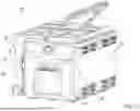
As shown in FIGS. 21, 24, and 26-28, the collection container 1120 of the vacuum assembly 1100 includes a body 1264 and a cover 1268 releasably couplable to the body 1264 to at least partially define and enclose a collection volume 1172 therebetween. The collection container 1120 also includes a filter mount 1178, an inlet port 1168, and a filter outlet port 1252. As shown in FIG. 27, the container 1120 also includes a latch 1604 configured to secure the cover 1268 to the body 1264.
The body 1264 of the container 1120 includes a base wall 1272 and a plurality of side walls 1276 extending from the periphery of the base wall 1272 to define an open end 1280 opposite thereof. The open end 1280, in turn, provides access to the collection volume 1172 and serves as a connection interface for the cover 1268. In some embodiments, the body 1264 is formed as a single piece of material such that the resulting body 1264 is fluid-tight. In other embodiments, the body 1264 is fluid-tight at all points vertically below the open end 1280.
The cover 1268 of the container 1120 is configured to selectively enclose the open end 1280 of the body 1264 and restrict access to the collection volume 1172. The cover 1268 is adjustable between an attached position (see FIG. 26), in which the cover 1268 is attached to the body 1264 and at least partially restricts access to the collection volume 1172, and a detached position, in which the cover 1268 is not attached to the body 1264 and does not restrict access to the collection volume 1172 via the open end 1280. In the illustrated embodiment, the cover 1268 at least partially restricts access to the collection volume 1172 via the open end 1280 and forms a fluid-tight interface with the body 1264 when in the attached position. The cover 1268 also includes the filter mount 1178, the inlet port 1168, the filter outlet port 1252, and defines a filter channel 1600 extending between the filter mount 1178 and the filter outlet port 1252.
As shown in FIG. 26, both the filter outlet port 1252 and the inlet port 1168 extend outwardly from a side wall of the cover 1268 such that the ports 1252, 1168 are positioned vertically within the height of the cover 1268 itself. In other embodiments, the ports 1252, 1168 are also positioned laterally within the width of the cover 1268. In still other embodiments, both ports 1252, 1168 are also positioned adjacent the top of the cover 1268 so that both ports 1252, 1168 are positioned as high as possible to limit any spillage during manipulation of the container 1120. In still other embodiments, both ports 1252, 1168 are formed into the cover 1268 and therefor positioned vertically above the open end 1280 of the body 1264.
During operation, the container 1120 is configured such that the cover 1268 can remain in the attached position as the container 1120 is inserted into and removed from the storage region 1144 of the body 1104. In such embodiments, the cover 1268 then serves to limit any spillage of the contents collected inside, especially liquids, when the container 1120 is being handled. Accordingly, the container 1120 is configured so that attaching and removing the cover 1268 from the body 1264 is independent of inserting and removing the container 1120 from the storage region 1144. In other embodiments, access to the volume 1172 of the container 1120 via the open end 1280 remains restricted as the container 1120 is inserted into and removed from the storage region 1144 of the body 1104.
Clause 1. A vacuum assembly comprising, a body; a blower assembly, wherein the blower assembly includes a blower motor defining a first blower axis; an inlet; a collection container in fluid communication with both the blower assembly and the inlet; and a filter in fluid communication with the blower assembly, wherein the filter defines a first filter axis, and wherein the first filter axis is parallel to and offset from the first blower axis.
Clause 2. The vacuum assembly of clause 1, wherein the filter is substantially cylindrical in shape.
Clause 3. The vacuum assembly of clause 1, wherein the filter includes an outlet port, and wherein the first filter axis is normal to the outlet port.
Clause 4. The vacuum assembly of clause 1, wherein the collection container is removably couplable to the body.
Clause 5. The vacuum assembly of clause 4, wherein the filter is at least partially positioned within the collection container when the collection container is coupled to the body.
Clause 6. The vacuum assembly of clause 1, wherein the body defines an internal volume, and wherein the blower assembly is at least partially positioned within the internal volume.
Clause 7. A vacuum assembly comprising, a vacuum body; a blower assembly, wherein the blower assembly includes an impeller rotatable about a first blower axis; an inlet; a collection container defining a collection volume in fluid communication with both the blower assembly and the inlet; and a filter in fluid communication with the blower assembly, wherein the filter defines a first filter axis, and wherein the first filter axis is parallel to and offset from the first blower axis.
Clause 8. The vacuum assembly of clause 7, wherein the filter is substantially cylindrical in shape.
Clause 9. The vacuum assembly of clause 7, wherein the blower assembly and the inlet are coupled to the body.
Clause 10. The vacuum assembly of clause 7, wherein the collection container is removably coupled to the body.
Clause 11. The vacuum assembly of clause 7, wherein the collection container includes container body and a container cover that together define the collection volume, and wherein the collection container may be detached from the vacuum body independent of detaching the cover from the container body.
Clause 12. The vacuum assembly of clause 7, wherein the impeller is a first impeller, the blower assembly further including: a second impeller rotatable about the first blower axis, and a blower housing, a first interior volume formed by the blower housing and sized to receive the first impeller therein, wherein the first interior volume has a first inlet in fluid communication with the collection volume, and a second interior volume formed by the blower housing and sized to receive the second impeller therein, wherein the second interior volume has a second inlet open an interior of the vacuum body.
Clause 13. The vacuum assembly of clause 12, wherein the second interior volume is at least partially nested within the first interior volume such that a reference plane oriented normal to the first blower axis will pass through both the first volume and the second volume simultaneously.
Clause 14. A vacuum assembly comprising, a body; a blower assembly, wherein the blower assembly includes a blower motor defining a first blower axis; an inlet; a collection container in fluid communication with both the blower assembly and the inlet; and a filter in fluid communication with the blower assembly, wherein the filter is positioned so that a reference plane oriented perpendicular to the first blower axis will pass through both the blower assembly and the filter simultaneously.
Clause 15. The vacuum assembly of clause 14, wherein the blower assembly further includes an impeller.
Clause 16. The vacuum assembly of clause 14, wherein the reference plane passes through both the blower motor and the filter simultaneously.
Clause 17. The vacuum assembly of clause 14, wherein the filter includes filtering material, and wherein the reference plane passes through both the blower motor and the filtering material simultaneously.
Clause 18. The vacuum assembly of clause 14, wherein the collection container is releasably couplable to the body along a first connection axis, and wherein the first blower axis is perpendicular to the first connection axis.
Clause 19. The vacuum assembly of clause 18, wherein the filter is at least partially positioned within the collection container.
Clause 20. The vacuum assembly of clause 14, further comprising a vacuum tube extending between and in fluid communication with both the blower assembly and the filter.
Clause 21. A vacuum assembly comprising, a vacuum body; an inlet; a collection container defining a collection volume in fluid communication with both the blower assembly and the inlet; and a blower assembly including a blower motor defining a first blower axis, a first impeller driven by the blower motor, a second impeller driven by the blower motor, a first interior volume sized to receive the first impeller therein, and wherein the first interior volume has a first inlet in fluid communication with the collection volume, a second interior volume sized to receive a second impeller therein, wherein the second interior volume has a second inlet in fluid communication with an interior of the vacuum body, and wherein the second interior volume is nested within the first interior volume such that a reference plane oriented normal to the first blower access will pass through both the first interior volume and the second interior volume simultaneously.
Clause 22. The vacuum assembly of clause 21, wherein the first interior volume and the second interior volume are substantially toroidal in shape.
Clause 23. The vacuum assembly of clause 21, wherein the first interior volume includes a first outlet open to the exterior of the vacuum body.
Clause 24. The vacuum assembly of clause 21, wherein the second interior volume includes a second outlet open to the exterior of the vacuum body.
Clause 25. The vacuum assembly of clause 21, wherein the blower motor is in fluid communication with the second interior volume.
Clause 26. A vacuum assembly comprising: a vacuum body defining a first volume; an inlet; a blower assembly; and a collection container defining a collection volume and movable between a first position, in which the collection container is at least partially positioned within the first volume and the collection volume is in fluid communication with the inlet and the blower assembly, and a second position, in which the collection container is not positioned within the first volume and the collection volume is not in fluid communication with the inlet or the blower assembly, the collection container including: a container body, a cover coupled to the container body to at least partially define the collection volume, and wherein the collection container is configured so that it can be moved from the first position to the second position without detaching the cover from the container body.
Clause 27. The vacuum assembly of clause 26, wherein the cover is coupled to the body to form a fluid-tight seal therebetween.
Clause 28. The vacuum assembly of clause 26, wherein the cover is attachable to the container body to selectively restrict access to the collection volume.
Clause 29. The vacuum assembly of clause 26, wherein the collection container is completely positionable within the first volume.
Clause 30. The vacuum assembly of clause 26, wherein the vacuum assembly is a wet/dry vacuum.
Claims
What is claimed is:1. A vacuum assembly comprising:
a body;
a blower assembly, wherein the blower assembly includes a blower motor defining a first blower axis;
an inlet;
a collection container in fluid communication with both the blower assembly and the inlet; and
a filter in fluid communication with the blower assembly, wherein the filter defines a first filter axis, and wherein the first filter axis is parallel to and offset from the first blower axis.
2. The vacuum assembly of claim 1, wherein the filter is substantially cylindrical in shape.
3. The vacuum assembly of claim 1, wherein the filter includes an outlet port, and wherein the first filter axis is normal to the outlet port.
4. The vacuum assembly of claim 1, wherein the collection container is removably couplable to the body.
5. The vacuum assembly of claim 4, wherein the filter is at least partially positioned within the collection container when the collection container is coupled to the body.
6. The vacuum assembly of claim 1, wherein the body defines an internal volume, and wherein the blower assembly is at least partially positioned within the internal volume.
7. A vacuum assembly comprising:
a vacuum body;
a blower assembly, wherein the blower assembly includes an impeller rotatable about a first blower axis;
an inlet;
a collection container defining a collection volume in fluid communication with both the blower assembly and the inlet; and
a filter in fluid communication with the blower assembly, wherein the filter defines a first filter axis, and wherein the first filter axis is parallel to and offset from the first blower axis.
8. The vacuum assembly of claim 7, wherein the filter is substantially cylindrical in shape.
9. The vacuum assembly of claim 7, wherein the blower assembly and the inlet are coupled to the vacuum body.
10. The vacuum assembly of claim 7, wherein the collection container is removably coupled to the vacuum body.
11. The vacuum assembly of claim 7, wherein the collection container includes container body and a container cover that together define the collection volume, and wherein the collection container may be detached from the vacuum body independent of detaching the cover from the container body.
12. The vacuum assembly of claim 7, wherein the impeller is a first impeller, the blower assembly further including:
a second impeller rotatable about the first blower axis, and
a blower housing,
a first interior volume formed by the blower housing and sized to receive the first impeller therein, wherein the first interior volume has a first inlet in fluid communication with the collection volume, and
a second interior volume formed by the blower housing and sized to receive the second impeller therein, wherein the second interior volume has a second inlet open an interior of the vacuum body.
13. The vacuum assembly of claim 12, wherein the second interior volume is at least partially nested within the first interior volume such that a reference plane oriented normal to the first blower axis will pass through both the first interior volume and the second interior volume simultaneously.
14. A vacuum assembly comprising:
a body;
a blower assembly, wherein the blower assembly includes a blower motor defining a first blower axis;
an inlet;
a collection container in fluid communication with both the blower assembly and the inlet; and
a filter in fluid communication with the blower assembly, wherein the filter is positioned so that a reference plane oriented perpendicular to the first blower axis will pass through both the blower assembly and the filter simultaneously.
15. The vacuum assembly of claim 14, wherein the blower assembly further includes an impeller.
16. The vacuum assembly of claim 14, wherein the reference plane passes through both the blower motor and the filter simultaneously.
17. The vacuum assembly of claim 14, wherein the filter includes filtering material, and wherein the reference plane passes through both the blower motor and the filtering material simultaneously.
18. The vacuum assembly of claim 14, wherein the collection container is releasably couplable to the body along a first connection axis, and wherein the first blower axis is perpendicular to the first connection axis.
19. The vacuum assembly of claim 18, wherein the filter is at least partially positioned within the collection container.
20. The vacuum assembly of claim 14, further comprising a vacuum tube extending between and in fluid communication with both the blower assembly and the filter.
Images & Drawings included:


Sources:
- United States Patent and Trademark Office - verify current appl. status at the USPTO↗
Similar patent applications:
- » 20250303584
VACUUMIZING ASSEMBLY AND VACUUMIZING DEVICE WITH REPLACEABLE VACUUMIZING ASSEMBLY - » 20230290592
Vacuum interrupter assembly, switchgear including vacuum interrupter assembly, and method of configuring vacuum interrupter assembly - » 20210080028
Valve assembly, vacuum assembly and method - » 20220243737
VACUUM ASSEMBLY AND VACUUM PUMP WITH AN AXIAL THROUGH PASSAGE - » 20260098529
EJECTOR-TYPE VACUUM PUMP ASSEMBLY HAVING STABILISED MEMBRANE FLOW VALVE, AND A FLOW CONTROL UNIT HAVING STABILISED MEMBRANE FLOW VALVE FOR USE WITH AN EJECTOR-TYPE VACUUM PUMP OF SUCH ASSEMBLY, AND A METHOD OF CON-TROLLING A VACUUM LEVEL IN A VACUUM CHAMBER OF AN EJECTOR-TYPE VACUUM PUMP OF THE ASSEMBLY - » 20170273518
Wet/dry, non-porous bag/bagless vacuum assembly with steam and variable speed settable vacuum motor control with no loss of suction - » 20120311814
Wet/dry, non-porous bag/bagless vacuum assembly with steam and variable speed settable vacuum motor control with no loss of suction - » 20120233805
Vacuum motor scroll assembly and vacuums including such an assembly - » 20140201943
Vacuum Motor Scroll Assembly and Vacuums Including Such an Assembly - » 20080202602
Valve Controlled Vacuum Assembly
Recent applications in this class:
- » 20240164601 2024-05-23
Vacuum cleaner filter cartridge - » 20240032750 2024-02-01
MESH PREFILTER FOR VACUUM DEVICE - » 20230337876 2023-10-26
Floor cleaner - » 20230210330 2023-07-06
LID ARRANGEMENT FOR A DUST EXTRACTOR COMPRISING A DUST CYCLONE CONTAINER AND A FINE FILTER SECTION - » 20220151449 2022-05-19
VACUUM CLEANER - » 20220133107 2022-05-05
Vacuum cleaner filter cartridge - » 20210401248 2021-12-30
VACUUM CLEANER AND FILTER ASSEMBLY - » 20210321844 2021-10-21
VACUUM FILTER HAVING PASS-THROUGH CATCH - » 20210145230 2021-05-20
FLOOR CLEANER - » 20210127924 2021-05-06
Dust collector