Exercise Machine Carriage Handles
US20260166366A1
2026-06-18
18/984,397
2024-12-17
Smart Summary: An exercise machine features a carriage with handles on the sides. Inside this carriage, there are three support pads that help stabilize it. The frame of the carriage is made of a grid of vertical and horizontal pieces, making it strong and sturdy. This design allows users to perform various exercises comfortably and safely. Overall, the setup provides flexibility for different workout positions and movements. 🚀 TL;DR
Abstract:
A carriage for an exercise machine comprises longitudinal and lateral handles defining the outer periphery of the carriage. First, second, and third support pads are positioned within this outer perimeter and coupled to a rectangular carriage frame. The carriage frame is constructed from interconnected vertical and horizontal segments arranged in a grid pattern. This grid structure provides enhanced rigidity and support to the carriage assembly. The integrated handle system and support pad arrangement create a versatile user interface that accommodates a wide range of exercise positions and movements.
Inventors:
- Sebastien Anthony Louis Lagree 99 🇺🇸 Chatsworth, CA, United States
- Max E. Wunderlich 15 🇺🇸 Los Angeles, CA, United States
Applicant:
Interested in similar patents?
Get notified when new applications in this technology area are published.
Classification:
A63B21/4035 » CPC main
Exercising apparatus for developing or strengthening the muscles or joints of the body by working against a counterforce, with or without measuring devices; Interfaces with the user related to strength training; Details thereof; Specific exercise interfaces; Handles, pedals, bars or platforms for operation by hand
A63B21/00065 » CPC further
Exercising apparatus for developing or strengthening the muscles or joints of the body by working against a counterforce, with or without measuring devices; Mechanical means for varying the resistance by increasing or reducing the number of resistance units
A63B21/00069 » CPC further
Exercising apparatus for developing or strengthening the muscles or joints of the body by working against a counterforce, with or without measuring devices; Mechanical means for varying the resistance Setting or adjusting the resistance level; Compensating for a preload prior to use, e.g. changing length of resistance or adjusting a valve
A63B21/154 » CPC further
Exercising apparatus for developing or strengthening the muscles or joints of the body by working against a counterforce, with or without measuring devices; Arrangements for force transmissions; Using flexible elements for reciprocating movements, e.g. ropes or chains using special pulley-assemblies
A63B21/00 IPC
Exercising apparatus for developing or strengthening the muscles or joints of the body by working against a counterforce, with or without measuring devices
Description
CROSS-REFERENCE TO RELATED APPLICATIONS
Not applicable to this application.
STATEMENT REGARDING FEDERALLY SPONSORED RESEARCH OR DEVELOPMENT
Not applicable to this application.
BACKGROUND
Exercise machines incorporating movable carriages have traditionally employed basic handle configurations that limit user engagement and exercise versatility. Conventional carriage handles are typically mounted directly to a platform, creating fixed geometric relationships that restrict natural movement patterns and limit biomechanical effectiveness during exercise.
Prior handle systems often utilize rigid mounting approaches that concentrate structural loads at specific connection points. These direct mounting methods can create unwanted stress concentrations and fail to provide optimal load distribution throughout the support structure. Additionally, conventional handle designs frequently lack the sophisticated spatial relationships needed to accommodate varied user positions and movement patterns.
Existing exercise machines commonly employ handles that are either permanently affixed to a carriage or mounted through simple bracket arrangements. These basic mounting approaches fail to provide the precise geometric relationships needed for advanced exercise movements. The direct connection between handles and carriage platforms in conventional designs can result in a restricted range of motion and reduced exercise effectiveness.
Traditional handle configurations often lack the structural sophistication needed to maintain consistent spacing relationships throughout the full range of carriage movement. Many existing designs employ basic mounting brackets that fail to optimize load distribution while limiting the potential for complex compound movements during exercise.
SUMMARY
According to some embodiments, the present disclosure is directed to an exercise machine. The exercise machine also includes a frame having a first end, a second end, and a longitudinal axis, the frame including first and second guide rails extending substantially between the first end and the second end. The machine also includes a carriage movably mounted on the first and second guide rails for reciprocating movement along the longitudinal axis. The machine also includes first, second, and third support plates mounted on the frame, where the first support plate is positioned at the first end, the second support plate is positioned at an intermediate position between the first end and the second end, and the third support plate is positioned proximate the second end. The machine also includes first and second connecting rods extending between and interconnecting the first, second, and third support plates. The machine also includes a triangular gusset member coupled to the frame, the triangular gusset member extending diagonally between intersecting frame components may include at least the second support plate, to distribute loads and enhance rigidity.
Implementations may include one or more of the following features. The exercise machine may include: a first outermost handle extending from the first support plate; a first upper peripheral handle extending upwardly from the frame and curving inwardly to define a boundary above a first fixed support pad; first and second ergonomic handles rising perpendicularly from the frame, each of the first and second ergonomic handles having an angled upper portion; and a first inner handle extending perpendicularly between the first and second ergonomic handles. The exercise machine may include: a second outermost handle extending from the third support plate; a second upper peripheral handle extending upwardly from the frame and curving inwardly to define a boundary above a second fixed support pad; third and fourth ergonomic handles rising perpendicularly from the frame, each of the third and fourth ergonomic handles having an angled upper portion; and a second inner handle extending perpendicularly between the third and fourth ergonomic handles.
The carriage may include: first and second longitudinal handles and first and second lateral handles defining an outer periphery of the carriage; first, second, and third support pads positioned within the outer periphery, the first, second, and third support pads coupled to a carriage frame; and the carriage frame disposed within the frame and having a rectangular configuration defined by interconnected vertical and horizontal segments arranged in a grid pattern. The exercise machine may include brackets supporting midpoints of the first and second longitudinal handles.
The exercise machine may include a tensioning assembly providing user-adjustable resistance, the tensioning assembly including a plurality of independently selectable tensioning units arranged in parallel along the frame. Each tensioning unit may include: a pulley rotatably mounted on a pulley support arm; an elastomeric member extending between a fixed anchor point on the frame and the pulley; an engagement mechanism for selectively coupling the elastomeric member to the carriage; and a tension adjustment mechanism for fine-tuning a baseline tension in the elastomeric member. Each of the first and second guide rails includes: an angled upper rail section sloping inwardly relative to the carriage and providing an inclined contact surface; and a lower rail section extending perpendicularly to the carriage and providing a horizontal contact surface. The exercise machine may include a wheel assembly mounted at each corner of the carriage, each wheel assembly including: a diagonal wheel maintaining contact with the angled upper rail section; and a vertical wheel maintaining contact with the lower rail section.
According to some embodiments, the present disclosure is directed to a carriage for an exercise machine. The carriage also includes first and second longitudinal handles and first and second lateral handles defining an outer periphery. The carriage also includes first, second, and third support pads positioned within the outer periphery. The carriage also includes a carriage frame coupled to the first, second, and third support pads, the carriage frame having a rectangular configuration defined by interconnected vertical and horizontal segments arranged in a grid pattern.
Implementations may include one or more of the following features. The carriage may include brackets supporting midpoints of the first and second longitudinal handles. The carriage may include wheel assemblies mounted at corners of the carriage frame, each wheel assembly including a diagonal wheel and a vertical wheel.
According to some embodiments, the present disclosure is directed to an exercise machine. The exercise machine also includes a frame having a first end, a second end, and a longitudinal axis. The machine also includes a carriage movably mounted on the frame for reciprocating movement along the longitudinal axis. The machine also includes first, second, and third support plates mounted on the frame. The machine also includes first and second outermost handles extending from the first and third support plates, respectively. The machine also includes first and second upper peripheral handles extending upwardly from the frame and curving inwardly to define boundaries above first and second fixed support pads, respectively. The machine also includes first, second, third, and fourth ergonomic handles rising perpendicularly from the frame, each ergonomic handle having an angled upper portion; and first and second inner handles extending perpendicularly between the first and second ergonomic handles and the third and fourth ergonomic handles, respectively.
Implementations may include one or more of the following features. The exercise machine may include first and second connecting rods extending between and interconnecting the first, second, and third support plates. The exercise machine may include a triangular gusset member coupled to the frame, the triangular gusset member extending diagonally between intersecting frame components to distribute loads and enhance rigidity. The exercise machine may include a tensioning assembly providing user-adjustable resistance, the tensioning assembly including a plurality of independently selectable tensioning units arranged in parallel along the frame.
Each tensioning unit may include a pulley rotatably mounted on a pulley support arm; an elastomeric member extending between a fixed anchor point on the frame and the pulley; an engagement mechanism for selectively coupling the elastomeric member to the carriage; and a tension adjustment mechanism for fine-tuning a baseline tension in the elastomeric member. The carriage may include: first and second longitudinal handles and first and second lateral handles defining an outer periphery of the carriage; first, second, and third support pads positioned within the outer periphery; and a carriage frame coupled to the first, second, and third support pads. The exercise machine may include brackets supporting midpoints of the first and second longitudinal handles. The exercise machine may include wheel assemblies mounted at corners of the carriage frame, each wheel assembly including a diagonal wheel and a vertical wheel.
There has thus been outlined, rather broadly, some of the embodiments of the present disclosure in order that the detailed description thereof may be better understood, and in order that the present contribution to the art may be better appreciated. There are additional embodiments that will be described hereinafter and that will form the subject matter of the claims appended hereto. In this respect, before explaining at least one embodiment in detail, it is to be understood that the various embodiments are not limited in its application to the details of construction or to the arrangements of the components set forth in the following description or illustrated in the drawings. Also, it is to be understood that the phraseology and terminology employed herein are for the purpose of the description and should not be regarded as limiting.
To better understand the nature and advantages of the present disclosure, reference should be made to the following description and the accompanying figures. It is to be understood, however, that each of the figures is provided for the purpose of illustration only and is not intended as a definition of the limits of the scope of the present disclosure. Also, as a general rule, and unless it is evidence to the contrary from the description, where elements in different figures use identical reference numbers, the elements are generally either identical or at least similar in function or purpose.
BRIEF DESCRIPTION OF THE DRAWINGS
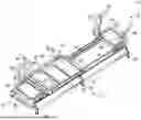
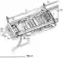
FIG. 1 is an isometric view of the exercise machine, illustrating the overall design, including the frame, carriage, handles, and support structures.
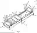
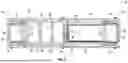
FIG. 2A is a perspective view focusing on the carriage frame of the exercise machine, including the guide rail system.
FIG. 2B is a perspective view of carriage mounting brackets.
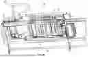
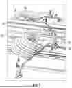
FIG. 3 is a bottom plan view of the exercise machine showing a tensioning assembly, elastomeric members, pulleys, and the engagement mechanisms, as well as a frame gusset.
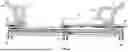
FIG. 4 is a side view of the exercise machine, detailing the frame, support plates, and handles on one end of the machine.
FIG. 5 is a top-down view of the carriage, illustrating the arrangement of the support pads, lateral handles, and longitudinal handles.
FIG. 6 is a detailed perspective view of the frame and carriage connection points, highlighting structural components and handle arrangements.
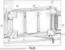
FIG. 7 is a cross-sectional view of the tensioning assembly, providing details of the elastomeric members, pulleys, and tension adjustment mechanisms.
FIG. 8 is a cross-sectional view of the guide rail system, showing the interaction between the carriage wheels and the guide rails.
DETAILED DESCRIPTION
U.S. Pat. Nos. 11,433,272 and 11,458,355, the entire disclosure of which, except for any definitions, disclaimers, disavowals, and inconsistencies, are incorporated herein by reference.
A. Overview
The present disclosure relates to an exercise machine having a longitudinally-extending frame assembly with integrated support elements. The frame incorporates first, second, and third support plates arranged along its length that transition from wider base portions to narrower upper sections through angled transitions. A triangular gusset member connects between frame elements to provide structural reinforcement and resist torsional forces generated during use.
The machine includes a carriage assembly supported on guide rails for reciprocating translation along the frame's longitudinal axis. The carriage incorporates three cushioned support pads arranged in series and mounted on a structural frame having a grid-like configuration of interconnected segments. Multiple handles surround the carriage perimeter, including longitudinal and lateral handles for user support during movement.
At each end of the frame, the machine features a comprehensive handle system with multiple grip configurations. Outermost handles extend horizontally before transitioning through vertical sections to inward-facing grip regions. Upper peripheral handles incorporate compound curves to create protective boundaries above fixed support pads, while ergonomic handles rise vertically before angling outward in their upper portions. Inner handles span horizontally between the ergonomic handles at each end.
In one embodiment, a resistance mechanism includes multiple independently selectable tensioning units arranged in parallel along the frame. Each unit incorporates an elastomeric member extending between a fixed anchor point and a pulley to provide mechanical advantage. The units include engagement mechanisms for selective activation and tension adjustment mechanisms for fine-tuning the baseline resistance. This parallel configuration enables incremental force adjustment through selective unit engagement, with each activated unit contributing additively to the system resistance.
The guide rail system features angled upper sections and horizontal lower sections engaged by diagonal and vertical wheels at each carriage corner, ensuring precise tracking and balanced load distribution during translation. This comprehensive system of handles, support surfaces, and adjustable resistance elements creates a versatile exercise platform capable of accommodating diverse workout routines while maintaining structural integrity under dynamic loading conditions.
The machine's features address limitations in existing exercise equipment by providing enhanced stability, precise resistance control, and multiple exercise positions through its integrated handle system and carriage configuration. The resistance mechanism's dual adjustment capability-through both selective unit engagement and individual tension adjustment-enables fine-tuned progression of exercise intensity while maintaining mechanical efficiency through its pulley-based force transmission system.
B. Example Embodiments
Referring now to FIGS. 1-5, exercise machine 10 comprises a longitudinally-extending frame 12 defined by first end 14 and second end 16. Frame 12 incorporates first and second guide rails 18, 20 that extend substantially between first end 14 and second end 16. First and second guide rails 18, 20 support carriage 22 for reciprocating translation along the longitudinal axis of frame 12.
Frame 12 incorporates first, second, and third support plates 26, 28, and 30. First support plate 26 is located at first end 14, third support plate 30 is located proximate the second end 16, and second support plate 28 is located at an intermediate position. Each support plate transitions from a wider base portion through angled transition sections to a narrower upper portion. The support plates include integrated mounting features for securing frame components and handle assemblies. First and second connecting rods 32, 34 span between adjacent support plates to form a rigid structural assembly.
A triangular gusset member 13 provides structural reinforcement between the horizontal and vertical elements of the frame 12. At its narrowest point, the gusset member 13 couples to the second support plate 28 and at a larger end to a frame member 15 that supports a first fixed support pad 40 (discussed in greater detail below). The gusset member 13 extends diagonally between intersecting frame components to distribute loads and enhance the overall rigidity of the frame 12. The triangular configuration of the gusset member 13 effectively transfers forces between the joined frame elements and resists torsional forces produced by the movement of the carriage when under biased tension.
At first end 14, first outermost handle 36 comprises a tubular member that extends horizontally outward from first support plate 26, transitions through an approximately 90-degree bend to create a vertical section, then bends inward to form a horizontal gripping portion parallel to frame 12. First upper peripheral handle 38 extends upward from its mounting point on frame 12 through a compound curve-first transitioning outward, then curving inward while maintaining a constant vertical rise to create a protective boundary above first fixed support pad 40. First fixed support pad 40 comprises a cushioned platform with a substantially rectangular profile. First and second ergonomic handles 42, 44 comprise vertical tubular sections that rise perpendicular to frame 12, then incorporate outward angles in their upper portions to create angled grip regions. First inner handle 53 spans horizontally between handles 42, 44 at a perpendicular orientation to the longitudinal axis of frame 12.
At second end 16, second outermost handle 46 (see FIG. 5) replicates the horizontal-vertical-horizontal geometry of first outermost handle 36. Second upper peripheral handle 48 mirrors the compound curved profile of first upper peripheral handle 38 to create a protective boundary above second fixed support pad 50. Second fixed support pad 50 comprises a cushioned platform similar to first fixed support pad 40. Third and fourth ergonomic handles 52, 54 are similar to the vertical-to-angled configuration of first and second ergonomic handles 42, 44. Second inner handle 55 spans horizontally between third and fourth ergonomic handles 52, 54, maintaining a perpendicular orientation to frame 12.
Carriage 22 includes first and second longitudinal handles 56, 58 and first and second lateral handles 60, 62 defining an outer periphery of the carriage 22. Within this periphery, carriage 22 incorporates first, second and third support pads 64, 66, 68 coupled to carriage frame 70 (see FIG. 2A). First support pad 64 comprises a rectangular cushioned member positioned at a first end of carriage 22. Second support pad 66 comprises a similar rectangular cushioned member positioned centrally on carriage 22. Third support pad 68 comprises a rectangular cushioned member positioned at a second end of carriage 22. The support pads are arranged in series along the longitudinal axis of carriage 22, with each pad having substantially similar width dimensions matching the spacing between first and second lateral handles 60, 62. In some instances, first and second lateral handles 60, 62 are supported at their respective midpoints by brackets 57 and 59.
As best shown in FIG. 2B, first and second longitudinal handles 56, 58 and first and second lateral handles 60, 62 define the outer periphery of carriage 22. The longitudinal and lateral handles intersect at mounting brackets positioned at each corner of the carriage frame 70.
The carriage 22 includes a first mounting bracket 61, a second mounting bracket 63, third mounting bracket 65, and a fourth mounting bracket 67. The first and second mounting brackets 61, 63 support first lateral handle 60, while third and fourth mounting bracket 65, 67 support first lateral handle 62. The first longitudinal handle 56 is supported by the second mounting bracket 63 and fourth mounting bracket 67. The second longitudinal handle 58 is supported by the first mounting bracket 61 and third mounting bracket 65.
Together, these mounting brackets create a rigid assembly that maintains consistent spacing between the handles and carriage frame 70. The symmetrical arrangement of mounting brackets 61, 63, 65, 67 at each corner of carriage frame 70 enables balanced engagement with the guide rail system while preserving proper spacing between the handles and support pads 64, 66, 68.
The mounting brackets 61, 63, 65, 67 connect the handles to carriage frame 70 while establishing the spacing between the handles and support pads 64, 66, 68. First and third corner mounting brackets 61, 65 include support sections that set the distance between first longitudinal handle 56 and first support pad 64. Second and fourth corner mounting brackets 63, 67 set the spacing between second longitudinal handle 58 and third support pad 68. These defined distances allow user access while supporting loads during exercise.
The mounting brackets also position second support pad 66 relative to the handle perimeter. The arrangement of mounting brackets 61, 63, 65, 67 forms a structural frame that maintains the shape of carriage frame 70 during use, keeping consistent spacing between the support pads and handles. The mounting bracket configuration sets and maintains the position of support pads 64, 66, 68 as the carriage moves along the guide rails.
The mounting brackets 61, 63, 65, 67 include structural sections that extend inward to connect with carriage frame 70. These connections form an integrated structure that holds the established distances between the handle system and support pads during both stationary and moving exercises.
In another embodiment, carriage 22 incorporates a continuous, unitary handle assembly that defines the outer periphery. Rather than separate longitudinal and lateral handles, a single tubular member forms a complete perimeter around the carriage frame 70. This continuous handle assembly comprises a bent tubular element that creates rounded corners transitioning between the longitudinal and lateral sections, eliminating the need for separate handle components and connection points.
The continuous handle maintains substantially the same dimensional footprint as the separate handle configuration, with longitudinal sections running parallel to the carriage's length and lateral sections spanning its width. The tubular member is formed from a single piece of material, bent to create smooth radiused transitions at each corner. These rounded corners provide additional grip positions while maintaining structural integrity through the elimination of mechanical joints.
The continuous handle assembly mounts to carriage frame 70 through a series of support brackets positioned along both the longitudinal and lateral sections. The brackets incorporate cushioning elements at the interface between the handle and frame to minimize vibration transfer during carriage translation.
The handle's tubular cross-section remains consistent throughout its circumference, providing uniform grip diameter for user comfort. The tube's material composition and wall thickness are selected to provide sufficient rigidity while maintaining appropriate flex characteristics for user comfort during dynamic loading conditions. Surface treatments or texturing may be applied to enhance grip security.
In one embodiment, the handles for the carriage 22 can be modular, and provided with quick-connect mounting points around the carriage perimeter or carriage frame 70. This allows users to rapidly reconfigure handle positions and types for different exercises.
The handles can also include a vertical adjustment mechanism to the carriage support pads. Each pad can independently raise, lower, or angle through a mechanical or pneumatic system, allowing users to create customized support surfaces for different exercises or body positions.
In yet another embodiment, any of the handles associated with the carriage can include rotating segments. For example, certain sections of a handle could be designed to rotate freely or with controlled resistance around their longitudinal axis. This allows users to perform exercises involving wrist rotation or to adjust their grip position during movement without releasing the handle. The rotating sections can incorporate bearings and adjustable friction elements to control the rotation.
In general, carriage frame 70 is a structural element with a generally rectangular configuration defined by a plurality of interconnected vertical and horizontal segments arranged in a grid-like pattern. Carriage frame 70 is located within frame 12 and provides enhanced structural rigidity and support to the carriage 22. The grid-like pattern of carriage frame 70 supports the first, second and third support pads 64, 66, 68.
Referring now to FIGS. 4 and 7, tensioning assembly 72 provides user-adjustable resistance during translation of carriage 22. The tensioning assembly 72 comprises a plurality of independently selectable tensioning units such as tensioning unit 74, arranged in a parallel configuration along frame 12, and engaged with second support plate 28.
Each tensioning unit 74 incorporates a pulley 76 that is rotatably mounted on a corresponding pulley support arm or shaft. An elastomeric member 78 extends between a fixed anchor point 80 on second support plate 28 (in one example the elastomeric member can be connected with a clip) and pulley 76 to provide the resistance force. This configuration enables the elastomeric member 78 to impart resistance against carriage movement through the mechanical advantage provided by pulley 76.
Each tensioning unit incorporates an engagement mechanism 82 that enables selective activation and deactivation of the unit's resistance contribution. One end of elastomeric member 78 is fixedly secured to the second support plate 28, while the opposite end includes an engagement mechanism 82 that can be selectively connected and disconnected. When engaged, the tensioning unit's elastomeric member 78 is placed under tension and mechanically coupled to resist carriage translation. When disengaged, the elastomeric member 78 is mechanically isolated from the resistance pathway. The parallel arrangement of multiple tensioning units enables incremental force adjustment through selective unit activation, with each engaged unit contributing additively to the aggregate system resistance.
A tension adjustment mechanism 84 enables fine-tuning of the baseline tension in each engaged elastomeric member 78. The adjustment mechanism 84 includes an adjustment shaft that threadedly engages elastomeric member 78. Adjustment of tension adjustment mechanism 84 varies the elongation and tension of elastomeric member 78. This allows precise calibration of the resistance force provided by each engaged tensioning unit.
The tension adjustment mechanism 84 provides precise control over the initial resistance characteristics of each tensioning unit 74. Through calibrated adjustment of mechanism 84, users can fine-tune the baseline tension-the foundational resistance level that must be overcome to initiate carriage movement. This fine-tuning capability operates independently for each tensioning unit 74, allowing customization of the baseline tension in incremental steps. When multiple tensioning units are engaged, their individually fine-tuned baseline tensions combine additively to create the aggregate system resistance.
The tension adjustment mechanism 84 achieves this precise baseline tension control through a threaded interface with the elastomeric member 78 mounting point. Rotating the adjustment mechanism clockwise increases the pre-load stretch of the elastomeric member 78, thereby elevating the baseline tension. Counter-clockwise rotation reduces the pre-load stretch, lowering the baseline tension. This mechanical advantage allows for minute adjustments to the resistance profile, enabling users to establish specific force thresholds suited to their exercise requirements. The ability to fine-tune baseline tension, combined with selective unit engagement, creates a highly adaptable resistance system capable of accommodating diverse user needs and supporting progressive strength development.
Referring now to FIG. 8, guide rail 20 incorporates an angled upper rail section 86 that slopes inward at approximately 45 degrees relative to carriage 22, providing an inclined contact surface extending the full length of the guide rail 20. Lower rail section 88 extends horizontally perpendicular to carriage 22, forming a level running surface parallel to the frame axis. The diagonally oriented wheel 90 is oriented to maintain full surface contact with upper rail section 86, while vertical oriented wheel 92 is positioned directly beneath it to engage the horizontal plane of lower rail section 88.
Guide rail 18 mirrors this configuration. Also, it will be understood that each corner of carriage 22 incorporates an identical wheel assembly configuration (diagonal and vertical wheels) to provide balanced engagement with guide rails 18, 20. This symmetrical arrangement ensures precise tracking and load distribution during carriage 22 translation along frame 12.
C. Operation of Example Embodiment
To operate the exercise machine, the user positions themselves on the carriage platform. The carriage is the movable portion that translates along the frame rails. It incorporates longitudinal handles 56, 58 and lateral handles 60, 62 along the perimeter that the user can grip for support and stability during various exercises.
Within this outer handle area, the carriage includes three cushioned support pads 64, 66, 68 mounted on the carriage frame 70. These pads provide surfaces for the user to sit, kneel, or lay on depending on the specific exercise being performed.
At each end of the machine, the user will find additional handles that expand the exercise options. First outermost handle 36 and second outermost handle 46 extend horizontally outward before transitioning to vertical and then inward horizontal sections, allowing the user to grasp them at various angles.
First upper peripheral handle 38 and second upper peripheral handle 48 rise up and curve inward, creating protective boundaries above the first and second fixed support pads 40, 50 located at each end of the machine. These upper handles give the user additional high gripping positions.
First and second ergonomic handles 42, 44 at the first end, and third and fourth ergonomic handles 52, 54 at the second end provide nearly vertical hand positions that angle outward slightly at the top. First inner handle 53 and second inner handle 55 span horizontally between these angled handles, serving as additional grip locations.
To perform an exercise, the user places themselves on the carriage, grasping any combination of the longitudinal, lateral, or inner handles. The user then engages the bias member resistance system by connecting a bias member between the carriage and the retainer. This provides resistance as the user pushes or pulls the carriage along the frame rails.
By gripping different handles and orienting their body in various positions on the carriage, the user can target specific muscle groups and perform a wide array of pushing, pulling, and leg exercises. The stationary handles at each end of the machine allow the user to exercise against the resistance while the carriage is at different points along the frame. The combination of handle options and carriage travel enables a highly versatile workout.
To adjust the resistance level, the user engages the tensioning assembly 72 located beneath the carriage 22. This assembly consists of multiple tensioning units 74 arranged in parallel.
Each tensioning unit 74 includes an elastomeric member 78, such as a bungee cord or elastic band, which spans between a fixed anchor point 80 on the frame and a movable pulley 76. The pulley 76 is mounted on a pulley support arm or shaft in a way that allows it to rotate. This pulley system provides a mechanical advantage, multiplying the resistance force generated by stretching the elastomeric member 78.
To engage a tensioning unit 74, the user connects the free end of the elastomeric member 78 to the carriage 22 using the engagement mechanism 82. This mechanism could be a simple hook or carabiner that attaches to a designated point on the underside of the carriage frame 70. Once engaged, the elastomeric member 78 will stretch as the carriage 22 moves along the frame 12, providing resistance to the user's movement.
The user can select the desired resistance level by choosing how many tensioning units 74 to engage. Since the units are arranged in parallel, each additional engaged unit adds incrementally to the total resistance force. For example, if each individual tensioning unit provides 10 pounds of resistance, then engaging two units would provide 20 pounds of total resistance, engaging three units would provide 30 pounds, and so on.
To further refine the resistance settings, each tensioning unit 74 also includes a tension adjustment mechanism 84. This mechanism allows the user to modify the initial pre-stretch of the elastomeric member 78. By tightening the adjustment mechanism 84, the user can increase the baseline tension in the elastomeric member 78 even when the carriage 22 is at rest. This effectively increases the resistance force that the user needs to overcome to initiate movement of the carriage 22 from a stationary position.
Thus, the user has two ways to modify the overall resistance level of the machine, either selecting the number of tensioning units 74 to engage, which determines the magnitude of the resistance force (i.e., light, medium, heavy), and/or adjusting the pre-stretch of each engaged tensioning unit 74, which fine-tunes the initial resistance and response curve within each broader resistance level.
This dual adjustment system provides the user with a wide range of resistance options to accommodate different exercise goals and fitness levels. The user can start with a low resistance setting by engaging only one tensioning unit 74 with minimal pre-stretch, and then progressively increase the challenge by engaging additional units and/or increasing their pre-stretch as their strength improves over time. This allows for very targeted and gradual progression, which is important for safe and effective resistance training.
Any and all headings are for convenience only and have no limiting effect. Unless otherwise defined, all technical and scientific terms used herein have the same meaning as commonly understood by one of ordinary skill in the art to which this invention belongs. Although specific terms are employed herein, they are used in a generic and descriptive sense only and not for purposes of limitation. All patent applications, patents, and printed publications cited herein are incorporated herein by reference in their entireties, except for any definitions, subject matter disclaimers or disavowals, and except to the extent that the incorporated material is inconsistent with the express disclosure herein, in which case the language in this disclosure controls.
The present invention may be embodied in other specific forms without departing from the spirit or essential attributes thereof, and it is therefore desired that the present embodiment be considered in all respects as illustrative and not restrictive. Many modifications and other embodiments of the present disclosure will come to mind to one skilled in the art to which this invention pertains and having the benefit of the teachings presented in the foregoing description and the associated drawings. Therefore, it is to be understood that the invention is not to be limited to the specific embodiments disclosed and that modifications and other embodiments are intended to be included within the scope of the appended claims. Although methods and materials similar to or equivalent to those described herein can be used in the practice or testing of the embodiments in the present disclosure, suitable methods and materials are described above. Thus, the present disclosure is not intended to be limited to the embodiments shown, but is to be accorded the widest scope consistent with the principles and features disclosed herein.
While various embodiments have been described above, it should be understood that they have been presented by way of example only, and not limitation. The descriptions are not intended to limit the scope of the technology to the particular forms set forth herein. To the contrary, the present descriptions are intended to cover such alternatives, modifications, and equivalents as may be included within the spirit and scope of the technology as defined by the appended claims and otherwise appreciated by one of ordinary skill in the art. The various embodiments of the present disclosure may be embodied in other specific forms without departing from the spirit or essential attributes thereof, and it is therefore desired that the various embodiments in the present disclosure be considered in all respects as illustrative and not restrictive. Thus, the breadth and scope of a preferred embodiment should not be limited by any of the above-described exemplary embodiments.
Unless otherwise defined, all technical and scientific terms used herein have the same meaning as commonly understood by one of ordinary skill in the art to which this invention belongs. All patent applications, patents, and printed publications cited herein are incorporated herein by reference in their entireties, except for any definitions, subject matter disclaimers or disavowals, and except to the extent that the incorporated material is inconsistent with the express disclosure herein, in which case the language in this disclosure controls. Any headings utilized within the description are for convenience only and have no legal or limiting effect.
Claims
What is claimed is:1. An exercise machine, comprising:
a frame having a first end, a second end, and a longitudinal axis, the frame including first and second guide rails extending substantially between the first end and the second end;
a carriage movably mounted on the first and second guide rails for reciprocating movement along the longitudinal axis;
first, second, and third support plates mounted on the frame, wherein the first support plate is positioned at the first end, the second support plate is positioned at an intermediate position between the first end and the second end, and the third support plate is positioned proximate the second end;
first and second connecting rods extending between and interconnecting the first, second, and third support plates; and
a triangular gusset member coupled to the frame, the triangular gusset member extending diagonally between intersecting frame components comprising at least the second support plate.
2. The exercise machine of claim 1, further comprising:
a first outermost handle extending from the first support plate;
a first upper peripheral handle extending upwardly from the frame and curving inwardly to define a boundary above a first fixed support pad;
first and second ergonomic handles rising perpendicularly from the frame, each of the first and second ergonomic handles having an angled upper portion; and
a first inner handle extending perpendicularly between the first and second ergonomic handles.
3. The exercise machine of claim 2, further comprising:
a second outermost handle extending from the third support plate;
a second upper peripheral handle extending upwardly from the frame and curving inwardly to define a boundary above a second fixed support pad;
third and fourth ergonomic handles rising perpendicularly from the frame, each of the third and fourth ergonomic handles having an angled upper portion; and
a second inner handle extending perpendicularly between the third and fourth ergonomic handles.
4. The exercise machine of claim 1, wherein the carriage comprises:
first and second longitudinal handles and first and second lateral handles defining an outer periphery of the carriage;
first, second, and third support pads positioned within the outer periphery, the first, second, and third support pads coupled to a carriage frame; and the carriage frame disposed within the frame and having a rectangular configuration defined by interconnected vertical and horizontal segments arranged in a grid pattern.
5. The exercise machine of claim 4, further comprising brackets supporting midpoints of the first and second longitudinal handles.
6. The exercise machine of claim 1, further comprising a tensioning assembly providing user-adjustable resistance, the tensioning assembly including a plurality of independently selectable tensioning units arranged in parallel along the frame.
7. The exercise machine of claim 6, wherein each tensioning unit comprises:
a pulley rotatably mounted on a pulley support arm;
an elastomeric member extending between a fixed anchor point on the frame and the pulley;
an engagement mechanism for selectively coupling the elastomeric member to the carriage; and a tension adjustment mechanism for fine-tuning a baseline tension in the elastomeric member.
8. The exercise machine of claim 1, wherein each of the first and second guide rails includes: an angled upper rail section sloping inwardly relative to the carriage and providing an inclined contact surface; and a lower rail section extending perpendicularly to the carriage and providing a horizontal contact surface.
9. The exercise machine of claim 8, further comprising a wheel assembly mounted at each corner of the carriage, each wheel assembly including: a diagonal wheel maintaining contact with the angled upper rail section; and a vertical wheel maintaining contact with the lower rail section.
10. A carriage for an exercise machine, comprising:
first and second longitudinal handles and first and second lateral handles defining an outer periphery;
first, second, and third support pads positioned within the outer periphery; and
a carriage frame coupled to the first, second, and third support pads, the carriage frame having a rectangular configuration defined by interconnected vertical and horizontal segments arranged in a grid pattern.
11. The carriage of claim 10, further comprising brackets supporting midpoints of the first and second longitudinal handles.
12. The carriage of claim 10, further comprising wheel assemblies mounted at corners of the carriage frame, each wheel assembly including a diagonal wheel and a vertical wheel.
13. An exercise machine, comprising:
a frame having a first end, a second end, and a longitudinal axis;
a carriage movably mounted on the frame for reciprocating movement along the longitudinal axis;
first, second, and third support plates mounted on the frame;
first and second outermost handles extending from the first and third support plates, respectively;
first and second upper peripheral handles extending upwardly from the frame and curving inwardly to define boundaries above first and second fixed support pads, respectively;
first, second, third, and fourth ergonomic handles rising perpendicularly from the frame, each ergonomic handle having an angled upper portion; and first and second inner handles extending perpendicularly between the first and second ergonomic handles and the third and fourth ergonomic handles, respectively.
14. The exercise machine of claim 13, further comprising first and second connecting rods extending between and interconnecting the first, second, and third support plates.
15. The exercise machine of claim 13, further comprising a triangular gusset member coupled to the frame, the triangular gusset member extending diagonally between intersecting frame components to distribute loads and enhance rigidity.
16. The exercise machine of claim 13, further comprising a tensioning assembly providing user-adjustable resistance, the tensioning assembly including a plurality of independently selectable tensioning units arranged in parallel along the frame.
17. The exercise machine of claim 16, wherein each tensioning unit comprises: a pulley rotatably mounted on a pulley support arm; an elastomeric member extending between a fixed anchor point on the frame and the pulley; an engagement mechanism for selectively coupling the elastomeric member to the carriage; and a tension adjustment mechanism for fine-tuning a baseline tension in the elastomeric member.
18. The exercise machine of claim 13, wherein the carriage comprises: first and second longitudinal handles and first and second lateral handles defining an outer periphery of the carriage; first, second, and third support pads positioned within the outer periphery; and a carriage frame coupled to the first, second, and third support pads.
19. The exercise machine of claim 18, further comprising brackets supporting midpoints of the first and second longitudinal handles.
20. The exercise machine of claim 18, further comprising wheel assemblies mounted at corners of the carriage frame, each wheel assembly including a diagonal wheel and a vertical wheel.
Images & Drawings included:


Sources:
- United States Patent and Trademark Office - verify current appl. status at the USPTO↗
Similar patent applications:
- » 16181259
Exercise machine carriage handle system - » 16933517
Exercise machine carriage handle system - » 20160096059
Exercise machine carriage handle system - » 20160346593
Exercise machine carriage handle system - » 20170065846
Exercise machine carriage handle system - » 20170189741
Exercise machine carriage handle system - » 20220355158
Exercise machine carriage handle system
Recent applications in this class:
- » 20260166367 2026-06-18
EXERCISE ACCESSORY AND METHOD - » 20260158325 2026-06-11
Forearm Extensor Training Device, etc - » 20260158324 2026-06-11
Exercise Balancing Support Device - » 20260145022 2026-05-28
Multipurpose Exercise Attachment Handle - » 20260137975 2026-05-21
ROTATION-BASED TORSO TRAINING EXERCISE APPARATUS AND METHODS OF USING SAME - » 20260108773 2026-04-23
HANDLE FOR FITNESS EQUIPMENT - » 20260084003 2026-03-26
EXERCISE DEVICE - » 20260084002 2026-03-26
EXERCISE DEVICE - » 20260034398 2026-02-05
Exercise Wheel Apparatus - » 20260034397 2026-02-05
ROTATING STRAP CONNECTOR AND REMOVABLE HANDLE FOR EXERCISE EQUIPMENT