WASHING MACHINE AND CONTROL METHOD THEREOF
US20260168161A1
2026-06-18
19/429,687
2025-12-22
Smart Summary: A washing machine uses carbon dioxide instead of water for cleaning clothes. It has a storage tank that holds the carbon dioxide and a tub where the gas mixes with the laundry. The machine also has a distillation tank that vaporizes the carbon dioxide after it has been used. A compressor is included to compress the carbon dioxide, making it easier to use in the washing process. The system works in a cycle, continuously supplying the compressed carbon dioxide back to the tub for effective cleaning. 🚀 TL;DR
Abstract:
A washing machine includes: a storage tank storing carbon dioxide; a tub configured to accommodate the carbon dioxide discharged from the storage tank and laundry; a distillation tank configured to accommodate the carbon dioxide discharged from the tub, the accommodated carbon dioxide to be vaporized in the distillation tank; a compressor configured to compress the carbon dioxide discharged from the storage tank or the carbon dioxide discharged from the distillation tank; and a pressurization flow path connected to the tub to supply carbon dioxide compressed by the compressor to the tub in a pressurization cycle of supplying carbon dioxide to the tub.
Inventors:
- Hwangmook CHO 9 🇰🇷 Suwon-si, South Korea
- Jeongyun LEE 6 🇰🇷 Suwon-si, South Korea
- Yeajin CHO 4 🇰🇷 Suwon-si, South Korea
- Somin LEE 1 🇰🇷 Suwon-si, South Korea
Assignee:
- SAMSUNG ELECTRONICS CO., LTD. 96,140 🇰🇷 Suwon-si, South Korea
Applicant:
Interested in similar patents?
Get notified when new applications in this technology area are published.
Classification:
D06F43/005 » CPC main
Dry-cleaning apparatus or methods using volatile solvents Solvent condition control devices, e.g. humidity content
D06F43/007 » CPC further
Dry-cleaning apparatus or methods using volatile solvents Dry cleaning methods
D06F43/00 IPC
Dry-cleaning apparatus or methods using volatile solvents
Description
CROSS REFERENCE TO THE RELATED APPLICATION
This application is a continuation application, filed under 35 U.S.C. § 111 (a), of International Application PCT/KR2025/020356 filed on Dec. 2, 2025, and is based on and claims priority under 35 U.S.C. § 119 to Korean Patent Applications No. 10-2024-0186483, filed on Dec. 13, 2024 in the Korean Intellectual Property Office, the disclosures of which are incorporated by reference herein in their entireties.
TECHNICAL FIELD
The present disclosure relates to a washing machine and a control method thereof.
BACKGROUND ART
General washing machines clean laundry using water as a cleaning agent. Also, there are dry cleaning washing machines that use volatile organic compounds, instead of water, as a cleaning agent to clean laundry without using water. The dry cleaning washing machines use solvents-based or petroleum-based cleaning agents.
The washing machines that use water generate wastewater during the washing process, thereby polluting the environment, and the solvent-based and petroleum-based cleaning agents used in the dry cleaning washing machines are harmful to the human body and also pollute the environment.
Instead of the aforementioned cleaning agents, carbon dioxide can be used as a cleaning agent. Carbon dioxide, which has a lower viscosity than water, easily penetrates fibers and removes contaminants. After washing, carbon dioxide containing foreign materials is vaporized and separated from the foreign materials, and the vaporized carbon dioxide is reused.
Because carbon dioxide, which is one of the atmospheric components, does not pollute the environment and liquid carbon dioxide is vaporized and liquefied to be reused, carbon dioxide emissions are not large, which contributes to achieving carbon neutrality.
DISCLOSURE
Technical Problem
An aspect of the disclosure provides a washing machine capable of adjusting a pressure and temperature of a tub in a pressurization cycle, a washing cycle, and/or a rinsing cycle, and a control method thereof.
The technical object intended to be achieved by the present document is not limited to the above-mentioned technical objects, and other technical objects not mentioned will be clearly understood by one of ordinary skill in the technical art to which the present disclosure belongs from the following description.
Technical Solution
A washing machine according to an embodiment of the present disclosure may include a storage tank storing carbon dioxide, a tub configured to accommodate carbon dioxide discharged from the storage tank and laundry, a distillation tank configured to accommodate carbon dioxide discharged from the tub, wherein the accommodated carbon dioxide is vaporized in the distillation tank, a compressor configured to compress carbon dioxide discharged from the storage tank or carbon dioxide discharged from the distillation tank, and a pressurization flow path connected to the tub to supply carbon dioxide compressed by the compressor to the tub.
A control method of a washing machine according to an embodiment of the present disclosure may include detecting at least one value of an internal pressure or temperature of a tub, and based on the detected at least one value being less than a preset value, performing a compressive pressurization cycle of supplying carbon dioxide pressurized by a compressor to the tub.
A washing machine may comprises a storage tank to store carbon dioxide, a tub configured to accommodate the carbon dioxide discharged from the storage tank and laundry, a distillation tank configured to accommodate the carbon dioxide discharged from the tub, the accommodated carbon dioxide to be vaporized in the distillation tank, a compressor configured to compress the carbon dioxide discharged from the storage tank or the carbon dioxide discharged from the distillation tank, and a pressurization flow path connected to the tub to supply the carbon dioxide compressed by the compressor to the tub.
The pressurization flow path may include a first pressurization flow path connecting the storage tank, the compressor, and the tub so that the carbon dioxide discharged from the storage tank is compressed by the compressor and the compressed carbon dioxide is moved to the tub through the first pressurization flow path.
The washing machine may further comprise a first valve configured to open or close the first pressurization flow path, and a controller configured to control the compressor to compress the carbon dioxide discharged from the storage tank and to open the first valve to move the carbon dioxide discharged from the storage tank to the tub through the compressor.
The controller may be configured to simultaneously operate the compressor and first valve to open the first pressurization flow path to move the carbon dioxide discharged from the storage tank to the tub through the compressor.
The washing machine may further comprise a water level sensor configured to detect a water level of the tub, and a pressure-temperature sensor configured to output a detected value of at least one of a pressure and temperature inside the tub.
The controller may be configured to, in response to detecting a water level of the tub detected by the water level sensor being greater than or equal to a preset water level value: based on the detected value output from the pressure-temperature sensor being less than a preset value, start a first operation of moving the carbon dioxide discharged from the storage tank to the tub through the compressor; and based on the detected value being greater than or equal to the preset value, terminate the first operation.
The pressurization flow path may further include a second pressurization flow path connecting the distillation tank, the compressor, and the tub the carbon dioxide discharged from the distillation tank is compressed by the compressor and the compressed carbon dioxide is moved to the tub through the second pressurization flow path.
The washing machine may further comprise a second valve configured to open or close the second pressurization flow path; and a controller configured to control the compressor to compress the carbon dioxide discharged from the storage tank and open the second valve to move the carbon dioxide discharged from the distillation tank to the tub through the compressor.
The washing machine may further comprise a water level sensor configured to detect a water level of the tub; and a pressure-temperature sensor configured to output a detected value of at least one of a pressure and temperature inside the tub,
The controller may be configured to, according to a water level of the tub detected by the water level sensor being greater than or equal to a preset water level value: based on a detected value output from the pressure-temperature sensor being less than a preset value, start a second operation of moving the carbon dioxide discharged from the distillation tank to the tub through the compressor; and based on the detected value being greater than or equal to the preset value, terminate the second operation.
The washing machine may further comprise a pressure sensor configured to detect an internal pressure of the distillation tank.
The controller may be configured to: based on a detected value output from the pressure temperature sensor being less than a preset value, detect an internal pressure of the distillation tank through the pressure sensor; and based on the internal pressure of the distillation tank being greater than or equal to a preset pressure value, start a second operation of moving the carbon dioxide discharged from the distillation tank to the tub through the compressor.
The pressurization flow path may include: a first pressurization flow path connecting the storage tank, the compressor, and the tub so that the carbon dioxide discharged from the storage tank is compressed by the compressor and the compressed carbon dioxide is moved to the tub through the first pressurization flow path; and a second pressurization flow path connecting the distillation tank, the compressor, and the tub so that the carbon dioxide discharged from the distillation tank is compressed by the compressor and the compressed carbon dioxide is moved to the tub through the second pressurization flow path.
The washing machine may further comprise a first valve configured to open or close the first pressurization flow path; a second valve configured to open or close the second pressurization flow path; and a controller configured to control the first valve and the compressor to move the carbon dioxide discharged from the storage tank to the tub through the compressor, and control the second valve and the compressor to move carbon dioxide discharged from the distillation tank to the tub through the compressor.
The washing machine may further comprise a water level sensor configured to detect a water level of the tub; a pressure temperature sensor configured to output a detected value of at least one of a pressure and temperature inside the tub; and a pressure sensor configured to detect an internal pressure of the distillation tank.
The controller may be configured to, in response to detecting a water level of the tub detected by the water level sensor being greater than or equal to a preset water level value: based on the detected value output from the temperature sensor being less than a preset value and an internal pressure of the distillation tank, detected by the pressure sensor, being greater than or equal to a preset pressure value, perform a second operation of moving the carbon dioxide discharged from the distillation tank to the tub through the compressor before a first operation of moving the carbon dioxide discharged from the storage tank to the tub through the compressor.
The washing machine may include a compressive pressurization cycle of supplying carbon dioxide pressurized by the compressor to the tub through the pressurization flow path before a washing cycle or a rinsing cycle.
A control method of a washing machine may comprise a storage tank to store carbon dioxide, a tub configured to accommodate the carbon dioxide discharged from the storage tank and laundry, a compressor configured to compress the carbon dioxide discharged from the storage tank, and a pressurization flow path connecting the storage tank, the compressor, and the tub, the control method may comprise: detecting at least one value of an internal pressure and temperature inside a tub; and based on the detected at least one value being less than a preset value, performing a compressive pressurization cycle of supplying carbon dioxide pressurized by a compressor to the tub, the performing of a compressive pressurization cycle comprising: simultaneously operating the compressor and opening the pressurization flow path to move the carbon dioxide discharged from the storage tank to the tub through the compressor.
The control method may further comprise before the detecting of the at least one value of the internal pressure and temperature of the tub, performing a non-compressive pressurization cycle of supplying carbon dioxide directly to the tub from a storage tank storing the carbon dioxide.
The detecting of the at least one value of the internal pressure and temperature of the tub may comprise: detecting a water level of the tub; and based on the water level of the tub being greater than or equal to a preset water level value, detecting at least one of an internal pressure and temperature inside the tub.
The controller may be configured to simultaneously operate the compressor and first valve to open the first pressurization flow path to move the carbon dioxide discharged from the storage tank to the tub through the compressor.
DESCRIPTION OF DRAWINGS
FIG. 1 is a conceptual diagram for describing a flow of carbon dioxide in a washing machine according to an embodiment of the present disclosure.
FIG. 2 is a control block diagram of the washing machine according to the embodiment of the present disclosure.
FIG. 3 shows an example of an operation cycle of the washing machine according to the embodiment of the present disclosure.
FIG. 4 shows a process of supplying gaseous carbon dioxide to a tub in the washing machine according to the embodiment of the present disclosure.
FIG. 5 shows a process of supplying liquid carbon dioxide to a tub in the washing machine according to the embodiment of the present disclosure.
FIG. 6 shows a process of supplying gaseous carbon dioxide and liquid carbon dioxide from a tub to a distillation tank in the washing machine according to the embodiment of the present disclosure.
FIG. 7 shows a process of collecting carbon dioxide inside a distillation tank into a storage tank in the washing machine according to the embodiment of the present disclosure.
FIG. 8 shows a process of collecting carbon dioxide inside a tub into a storage tank in the washing machine according to the embodiment of the present disclosure.
FIG. 9 shows a process of supplying carbon dioxide from a storage tank into a tub by a compressor in the washing machine according to the embodiment of the present disclosure.
FIG. 10 is an example of a flowchart illustrating a control method of the washing machine according to the embodiment of the present disclosure.
FIG. 11 is a conceptual diagram for describing a flow of carbon dioxide in a washing machine according to an embodiment of the present disclosure.
FIG. 12 shows a process of supplying carbon dioxide from a distillation tank to a tub by a compressor in the washing machine according to the embodiment of the present disclosure.
FIG. 13 is an example of a flowchart illustrating a control method of the washing machine according to the embodiment of the present disclosure.
FIG. 14 is a conceptual diagram for describing a flow of carbon dioxide in a washing machine according to an embodiment of the present disclosure.
FIG. 15 shows a process of supplying carbon dioxide from a storage tank to a tub by a compressor and a process of supplying carbon dioxide from a distillation tank to the tub by the compressor in the washing machine according to the embodiment of the present disclosure.
FIG. 16 is a conceptual diagram for describing a flow of carbon dioxide in a washing machine according to an embodiment of the present disclosure.
FIG. 17 is a control block diagram of the washing machine according to the embodiment of the present disclosure.
FIG. 18 shows a process of circulating carbon dioxide discharged from a tub to the tub by a circulation pump and a thermostatic bath in the washing machine according to the embodiment of the present disclosure.
FIG. 19 is an example of a flowchart illustrating a control method of the washing machine according to the embodiment of the present disclosure.
FIG. 20 is a conceptual diagram for describing a flow of carbon dioxide in a washing machine according to an embodiment of the present disclosure.
FIG. 21 is a conceptual diagram for describing a flow of carbon dioxide in a washing machine according to an embodiment of the present disclosure.
FIG. 22 is a conceptual diagram for describing a flow of carbon dioxide in a washing machine according to the embodiment of the present disclosure.
FIG. 23 is an example of a flowchart illustrating a control method of the washing machine according to the embodiment of the present disclosure.
FIG. 24 is another example of a flowchart illustrating a control method of the washing machine according to the embodiment of the present disclosure.
MODES OF THE INVENTION
Various embodiments of the present disclosure and terms used therein are not intended to limit the technical features described in the present disclosure to particular embodiments, and it should be construed as including various modifications, equivalents, or alternatives of a corresponding embodiment.
With regard to description of drawings, similar reference numerals may be used for similar or related components.
A singular form of a noun corresponding to an item may include one item or a plurality of the items unless context clearly indicates otherwise.
As used herein, each of the expressions “A or B,” “at least one of A and B,” “at least one of A or B,” “A, B, or C,” “at least one of A, B, and C,” and “at least one of A, B, or C,” may include one or all possible combinations of the items listed together with a corresponding expression among the expressions.
The term “and/or” includes any and all combinations of one or more of a plurality of associated listed items.
As used herein, such terms as “1st” and “2nd” or “first” and “second” may be used to simply distinguish a corresponding component from another, and does not limit the components in other aspect (for example, importance or order).
It is to be understood that if a certain component (for example, a first component) is referred to, with or without the term “operatively” or “communicatively”, as “coupled with,” “coupled to,” “connected with,” or “connected to” another component (for example, a second component), it means that the component may be coupled with the other component directly (for example, wiredly), wirelessly, or via a third element.
It is to be understood that the terms such as “including” or “having,” etc., are intended to indicate the existence of the features, numbers, steps, operations, components, parts, or combinations thereof disclosed in the specification, and are not intended to preclude the possibility that one or more other features, numbers, steps, operations, components, parts, or combinations thereof may exist or may be added.
It is to be understood that if a certain component is referred to as being “coupled with,” “coupled to,” “supported on” or “in contact with” another component, it means that the component may be coupled with the other component directly or indirectly via a third component.
It will also be understood that when a certain component is referred to as being “on” or “over” another component, it can be directly on the other component or intervening components may also be present.
A washing machine according to various embodiments may include a housing that accommodates various components therein. The housing may be provided in a shape of a box having a laundry inlet at one side.
The washing machine may include a door for opening or closing the laundry opening. The door may be rotatably mounted on the housing by a hinge. At least one portion of the door may be transparent or translucent to show the inside of the housing.
The washing machine may include a drum that accommodates laundry.
The drum may perform operations according to a washing cycle and a rinsing cycle while rotating inside the housing. A plurality of through holes may be formed in a cylindrical wall of the drum.
The washing machine may include a driver configured to rotate the drum. The driver may include a driving motor, and a rotating shaft for transferring a driving force generated in the driving motor to the drum.
The driver may rotate the drum forward or backward to perform operations according to a washing cycle and a rinsing cycle.
The washing machine may include a control panel mounted on one side of the housing. The control panel may provide a user interface that enables a user to interact with the washing machine. The user interface may include at least one input interface and at least output interface.
The at least one input interface may convert sensory information received from a user into an electrical signal.
The at least one input interface may include a power button, an operation button, a course selection dial (or a course selection button), and a washing/rinsing button. The at least one input interface may include, for example, a tact switch, a push switch, a slide switch, a toggle switch, a micro switch, a touch switch, a touch pad, a touch screen, a jog dial, and/or a microphone, etc.
The at least one output interface may visually and aurally transfer information related to an operation of the washing machine to a user.
For example, the at least one output interface may transfer information related to a washing course and an operation time of the washing machine or a washing setting/rinsing setting to a user. Information related to an operation of the washing machine may be output through a screen, an indicator, a voice, etc. The at least one output interface may include, for example, a Liquid Crystal Display (LCD) panel, a Light Emitting Diode (LED) panel, a speaker, etc.
The washing machine may include a communication module for communicating with an external device by wire and/or wirelessly.
The communication module may include at least one of a short-range communication module or a long-distance communication module.
The communication module may transmit data to an external device (for example, a server, a user device, and/or another home appliance) or receive data from the external device. For example, the communication module may establish communication with a server and/or a user device and/or another home appliance to transmit/receive various data.
To this end, the communication module may establish a direct (for example, wired) communication channel or a wireless communication channel with the external device, and support communication through the established communication channel. According to an embodiment, the communication module may include a wireless communication module (for example, a cellular communication module, a short-range communication module, or a global navigation satellite system (GNSS) communication module) or a wired communication module (for example, a local area network (LAN) communication module or a power line communication module). A corresponding communication module among the communication modules may communicate with an external device through a first network (for example, a short-range communication network, such as Bluetooth, WiFi Direct, or Infrared data association (IrDA)) or a second network (for example, a long-distance communication network, such as a legacy cellular network, a 5-Generation (5G) network, a next-generation communication network, the Internet, or a computer network (for example, a LAN or a wide area network (WAN)). The various kinds of communication modules may be integrated into a single component (for example, a single chip) or implemented with a plurality of components (for example, a plurality of chips).
The short-range wireless communication module may include a Bluetooth communication module, a Bluetooth Low Energy (BLE) communication module, a Near Field Communication (NFC) communication module, a Wireless Local Area Network (WLAN; WiFi) communication module, a Zigbee communication module, an IrDA communication module, a Wi-Fi Direct (WFD) communication module, a Ultrawideband (UWB) communication module, an Ant+ communication module, a microwave (uWave) communication module, etc., although not limited thereto.
The long-distance wireless communication module may include a communication module that performs various kinds of long-distance communications, and may include a mobile communication circuitry. The mobile communication circuitry may transmit/receive a wireless signal to/from at least one of a base station, an external terminal, or a server on a mobile communication network.
According to an embodiment, the communication module may communicate with an external device, such as a server, a user device, another home appliance, etc., through a surrounding AP. The AP may connect a LAN to which the washing machine or a user device is connected to a WAN to which a server is connected. The washing machine or the user device may be connected to the server through the WAN. A controller may control various components (for example, the driving motor) of the washing machine. The controller may control various components of the washing machine to perform at least one cycle including washing, rinsing, etc. according to a user input. For example, the controller may control the driving motor to adjust a rotational speed of the drum.
The controller may may include hardware, such as a central processing unit (CPU) or a memory, and software such as a control program. For example, the controller may include at least one memory that stores data in the form of an algorithm or program for controlling operations of components in the washing machine, and at least one processor that performs the above-described operations by using data stored in the at least one memory. The memory and the processor may be implemented with separate chips. The processor may include one, two, or more processor chips or one, two, or more processing cores. The memory may include one, two, or more memory chips or one, two, or more memory blocks. Also, the memory and the processor may be implemented with a single chip.
Hereinafter, an embodiment of the disclosure will be described in detail with reference to the accompanying drawings.
FIG. 1 is a conceptual diagram for describing a flow of carbon dioxide in a washing machine according to an embodiment of the present disclosure.
Referring to FIG. 1, a washing machine 1 according to an embodiment may include a storage tank 10, a chiller 11, a tub 20, a distillation tank 30, a compressor 50, and a foreign material tank 70.
The storage tank 10 may store carbon dioxide. The storage tank 10 may store gaseous carbon dioxide and liquid carbon dioxide. The storage tank 10 may be maintained at a preset internal pressure or higher to store liquid carbon dioxide. The storage tank 10 may store carbon dioxide at a first pressure level. For example, the first pressure level may range from about 30 bar to about 70 bar. In other words, an internal pressure of the storage tank 10 may range from about 30 bar to about 70 bar.
The storage tank 10 may include a first outlet through which gaseous carbon dioxide is mainly discharged, and a second outlet through which liquid carbon dioxide is mainly discharged. The storage tank 10 may include an inlet through which carbon dioxide flows into the storage tank 10 from an external source. The first outlet may be formed at a higher location than the second outlet such that liquid carbon dioxide inside the storage tank 10 is not discharged through the first outlet and gaseous carbon dioxide is discharged through the first outlet. The inlet may be formed at a higher location than the second outlet such that liquid carbon dioxide inside the storage tank 10 is not discharged through the inlet. For example, the first outlet and the inlet may be formed at a higher location than a full level of liquid carbon dioxide stored in the storage tank 10.
The chiller 11 may cool the storage tank 10. The chiller 11 may liquefy gaseous carbon dioxide inside the storage tank 10 by cooling the storage tank 10. Therefore, the chiller 11 may liquefy gaseous carbon dioxide collected from the tub 20 and the distillation tank 30. The liquefied carbon dioxide may be again discharged from the storage tank 10 to the tub 20 to be used for washing. The chiller 11 may liquefy carbon dioxide collected in a gaseous state to allow the carbon dioxide to circulate through the storage tank 10, the tub 20, and the distillation tank 30. The chiller 11 may include an evaporator of a heat pump. However, the chiller 11 may include at least one of various types of cooling devices.
According to an embodiment, the chiller 11 may liquefy gaseous carbon dioxide collected from the distillation tank 30 or the tub 20 into the storage tank 10 before the gaseous carbon dioxide enters the storage tank 10. Therefore, the gaseous carbon dioxide may not flow into the storage tank 10 and liquid carbon dioxide may flow into the storage tank 10. Causing liquid carbon dioxide to flow into the storage tank 10 may be more advantageous than causing gaseous carbon dioxide to flow into the storage tank 10 in view of safety. However, another cooling device than the chiller 11 may liquefy gaseous carbon dioxide collected from the distillation tank 30 or the tub 20 into the storage tank 10. The cooling device may include an evaporator of a heat pump.
The tub 20 may provide a space where laundry is washed with liquid carbon dioxide as a cleaning agent. The tub 20 may store liquid carbon dioxide and gaseous carbon dioxide therein. The tub 20 may be maintained at a preset internal pressure or higher to store liquid carbon dioxide therein. The tub 20 may be maintained at an internal pressure of about 30 bar to about 60 bar. Inside the tub 20, the drum (not shown) may be rotatably positioned.
The tub 20 may be positioned at a lower location than the storage tank 10. Accordingly, carbon dioxide stored in the storage tank 10 may move from the storage tank 10 to the tub 20 by gravity without power. Liquid carbon dioxide may mainly move to the tub 20 by gravity through the second outlet of the storage tank 10.
While laundry is put into the drum inside the tub 20, air may enter the tub 20. In the case where air enters the tub 20, moisture contained in the air may condense during a process of lowering an internal pressure of the tub 20 after washing is completed. When moisture penetrated into the laundry condenses, the laundry may be damaged. To prevent this, the washing machine 1 may include a vacuum pump 120 for discharging air inside the tub 20.
The distillation tank 30 may accommodate carbon dioxide and foreign materials discharged from the tub 20 after washing. More specifically, the distillation tank 30 may accommodate liquid carbon dioxide discharged from the tub 20, foreign materials dissolved or not dissolved in the liquid carbon dioxide, and gaseous carbon dioxide therein.
The washing machine 1 may collect carbon dioxide inside the distillation tank 30 into the storage tank 10. Gaseous carbon dioxide inside the distillation tank 30 may move to an inlet of the compressor 50 by a pressure difference, and the carbon dioxide moved to the inlet of the compressor 50 may be compressed by the compressor 50 and then move to the storage tank 10. Liquid carbon dioxide inside the distillation tank 30 may be vaporized by heat applied to the distillation tank 30. The vaporized gaseous carbon dioxide may move to the inlet of the compressor 50, be compressed by the compressor 50, and then move to the storage tank 10. While the liquid carbon dioxide is vaporized, foreign materials dissolved in the liquid carbon dioxide may be separated from the liquid carbon dioxide. The foreign materials inside the distillation tank 30 may be discharged to the foreign material tank 70 after the carbon dioxide inside the distillation tank 30 is collected into the storage tank 10.
In this process, gaseous carbon dioxide discharged from the distillation tank 30 may pass through the compressor 50 and become high-temperature and high-pressure gaseous carbon dioxide. The gaseous carbon dioxide of which a temperature has increased by passing through the compressor 50 may exchange heat with the distillation tank 30, thereby supplying heat to inside of the distillation tank 30. In the process of collecting carbon dioxide inside the distillation tank 30 into the storage tank 10, a temperature of the carbon dioxide passed through the compressor 50 may rise and heat of the carbon dioxide may be supplied to the distillation tank 30 to vaporize liquid carbon dioxide inside the distillation tank 30. According to an embodiment, high-temperature carbon dioxide passed through the compressor 50 may pass through the distillation tank 30 to exchange heat with carbon dioxide inside the distillation tank 30, thereby supplying heat to the distillation tank 30 without a heating source such as a separate heater. To supply more heat to the distillation tank 30, a heating device such as a heater may be added.
According to an embodiment, gaseous carbon dioxide collected from the distillation tank 30 into the storage tank 10 may exchange heat with the chiller 11 or a separate heat exchange before entering the storage tank 10 to be liquefied and then flow as liquid carbon dioxide into the storage tank 10. In other words, carbon dioxide collected from the distillation tank 30 into the storage tank 10 may flow in a liquid state into the storage tank 10. To this end, before gaseous carbon dioxide collected from the distillation tank 30 enters the storage tank 10, the gaseous carbon dioxide may be liquefied by the chiller 11 or cooled by the separate heat exchange to be liquefied. Liquefying gaseous carbon dioxide and then moving liquid carbon dioxide into the storage tank 10 may be more advantageous than moving gaseous carbon dioxide directly into the storage tank 10 in view of safety.
The foreign material tank 70 may store foreign materials discharged from the distillation tank 30. A user may discharge foreign materials stored in the foreign substance tank 70 at an appropriate cycle. The cycle for emptying the foreign material tank 70 may depend on a capacity of the foreign material tank 70 and an amount of foreign materials included in laundry.
The washing machine 1 according to an embodiment may further include a supplement tank 60.
The supplement tank 60 may supplement carbon dioxide lost in the process of collecting carbon dioxide after washing. The supplement tank 60 may store carbon dioxide therein. The supplement tank 60 may supply carbon dioxide to the tub 20. The supplement tank 60 may be separated from the washing machine 1. The supplement tank 60 may be replaced by another supplement tank. However, the supplement tank 60 may be separated from the washing machine 1, supplemented with carbon dioxide, and then coupled to the washing machine 1. An internal pressure of the supplement tank 60 may be equal to or higher than that of the storage tank 10. The internal pressure of the supplement tank 60 may be higher than that of the tub 20.
Referring to FIG. 1, the washing machine 1 may include a valve provided on a flow path along which carbon dioxide moves. The flow path may include a gas flow path along which gaseous carbon dioxide mainly moves, and a liquid flow path along which liquid carbon dioxide mainly moves. The valve may include a gas valve provided on the gas flow path along which gaseous carbon dioxide mainly moves and configured to open or close the gas flow path. The valve may include a liquid valve provided on the liquid flow path along which liquid carbon dioxide mainly moves and configured to open or close the liquid flow path. The washing machine 1 may include a flow path connection part at which a plurality of flow paths are combined into one flow path or one flow path diverges into a plurality of flow paths.
More specifically, the valve may include a first valve 101, a second valve 102, a third valve 103, a fourth valve 104, a fifth valve 105, a sixth valve 106, a seventh valve 107, an eight valve 108, a ninth valve 109, a tenth valve 110, a eleventh valve 111, a twelfth valve 112, a thirteenth valve 113, a fourteenth valve 114, and a sixteenth valve 116. The flow path may include a first flow path 201, a second flow path 202, a third flow path 203, a fourth flow path 204, a fifth flow path 205, a sixth flow path 206, a seventh flow path 207, an eight flow path 208, a ninth flow path 209, a tenth flow path 210, a eleventh flow path 211. The flow path connection part may include a first connection part 301, a second connection part 302, a third connection part 303, a fourth connection part 304, a fifth connection part 305, a sixth connection part 307 and an eighth connection part 308.
FIG. 2 is a control block diagram of the washing machine according to the embodimentthe embodiment of the present disclosure.
Referring to FIG. 2, the washing machine 1 may include a controller 80 that performs overall control operations.
The washing machine 1 may include the controller 80 including the processor 81 and the memory 82, the chiller 11, the compressor 50, a sensor portion 90, the valves 101 to 116, a driver 120, a communication circuitry 130, and a user interface 140.
The driver 120 may include a motor 120a for rotating the drum that accommodates laundry. The driver 120 may rotate the drum, which is rotatable inside the tub 20 and accommodates laundry therein, forward or backward by driving the motor 120 to perform operations according to a washing cycle and/or a rinsing cycle.
The communication circuitry 130 may include at least one communication module. The communication module may establish a direct (wired) communication channel or a wireless communication channel with an external device, and support communication through the established communication channel. According to an embodiment, the communication module may include a wireless communication module (for example, a cellular communication module, a short-range wireless communication module, or a GNSS communication module), or a wired communication module (for example, a LAN communication module or a power line communication module). A corresponding communication module among the communication modules may communicate with an external electronic device through a first network (for example, a short-range communication network, such as Bluetooth, WiFi direct, or IrDA) or a second network (for example, a telecommunication network, such as a legacy cellular network, a 5G network, a next-generation communication network, internet, or a computer network (for example, a LAN or WAN)). Such various kinds of communication modules may be integrated into a component (for example, a single chip) or implemented as a plurality of independent components (for example, a plurality of chips).
The short-range wireless communication module may include a Bluetooth communication module, a BLE communication module, a NFC communication module, a WLAN (WiFi) communication module, a Zigbee communication module, an IrDA communication module, a WFD communication module, a UWB communication module, an Ant+ communication module, a uWave communication module, etc., although not limited thereto.
The long-distance wireless communication module may include a communication module that performs various kinds of long-distance communications, and may include a mobile communication circuitry. The mobile communication circuitry may transmit/receive a wireless signal to/from at least one of a base station, an external terminal, and a server on a mobile communication network.
In an embodiment, the communication circuitry 130 may communicate with an external device, such as a server, a user device, another home appliance, etc., through a surrounding AP. The AP may connect a LAN to which the washing machine or a user device is connected to a WAN to which a server is connected. The washing machine or the user device may be connected to the server through the WAN.
The user interface 140 may include at least one input interface 141 and at least output interface 142.
The at least one input interface 141 may convert sensory information received from a user into an electrical signal.
The at least one input interface 141 may include a power button, an operation button, a course selection dial (or a course selection button), and a washing/rinsing setting button. The at least one input interface 141 may include, for example, a tact switch, a push switch, a slide switch, a toggle switch, a micro switch, a touch switch, a touch pad, a touch screen, a jog dial, and/or a microphone, etc.
The at least one output interface 142 may visually and aurally transfer information related to an operation of the washing machine 1 to a user.
For example, the at least one output interface 142 may transfer information related to a washing course and an operation time of the washing machine 1 and a washing setting/rinsing setting to a user. Information related to an operation of the washing machine 1 may be output through a screen, an indicator, a voice, etc. The at least one output interface 142 may include, for example, a LCD panel, a LED panel, and a speaker, etc.
The sensor portion 90 may include at least one sensor for obtaining information related to a state of the washing machine 1. The sensor portion 90 may transfer sensor data collected by the at least one sensor to the controller 80.
In an embodiment, the sensor portion 90 may include a water level sensor 91 that detects a water level of the tub 20, a pressure sensor 92 that detects an internal pressure of the tub 20, a temperature sensor 93 that detects an internal temperature of the tub 20, etc. The sensor portion 90 may include a pressure-temperature sensor 92 and 93, instead of the pressure sensor 92 and the temperature sensor 93. The pressure-temperature sensor 92 and 93 may output at least one of a temperature and pressure.
In various embodiments, the sensor portion 90 may include a pressure sensor that detects an internal pressure of the storage tank 10, a temperature sensor that detects an internal temperature of the storage tank 10, a pressure sensor that detects an internal pressure of the distillation tank 30, a temperature sensor that detects an internal temperature of the distillation tank 30, etc.
In an embodiment, the water level sensor 91 may detect an internal pressure of a connection hose connected to the tub 20 and output an electrical signal corresponding to the detected pressure to the controller 80. At this time, a water level of the connection hose may be equal to a water level of the tub 20. While a water level of the tub 20 rises, a water level of the connection hose may also rise, and according to the rise in water level of the connection hose, an internal pressure of the connection hose may increase.
The controller 80 may obtain a water level of the connection hose, that is, a water level of the tub 20 based on a pressure of the connection hose detected by the water level sensor 91. For example, the water level sensor 91 may detect a frequency that changes depending on a pressure of the connection hose. The controller 80 may obtain a water level of the tub 20 by analyzing a frequency (water level frequency) of an electrical signal corresponding to an output value from the water level sensor 91.
The controller 80 may receive water level data, pressure data, and temperature data detected by the sensor portion 90.
In an embodiment, the controller 80 may receive water level data, pressure data, and temperature data respectively detected by the water level sensor 91, the pressure sensor 92, and the temperature sensor 93. The controller 80 may control the compressor 50 and the first to sixth valves 101 to 106 based on the water level data, the pressure data, and the temperature data received from the water level sensor 91, the pressure sensor 92, and the temperature sensor 93.
The controller 80 may control the chiller 11, the compressor 50, the first to sixteenth valves 101 to 116, and the driver 120 to perform a pressurization cycle, a washing cycle, a rinsing cycle, a distillation cycle, and/or a depressurization cycle.
The controller 80 may be electrically connected to the chiller 11, the compressor 50, the sensor portion 90, the valves 101 to 116, the driver 120, the communication circuitry 130, and the user interface 140.
The controller 80 may be configured with hardware, such as central processing unit (CPU), Micom, or memory, and software such as a control program.
The controller 80 may be implemented with at least one memory 82 that stores algorithms for controlling operations of components in the washing machine 1, and data of program formats, and at least one processor 81 that performs the above-described operations using data stored in the at least one memory 82. The memory 82 and the processor 81 may be implemented as separate chips. Alternatively, the memory 82 and the processor 81 may be implemented as a single chip.
The processor 81 may include an operation circuit, a memory circuit, and a control circuit that process an output signal from the chiller 11, the compressor 50, the sensor portion 90, the valves 101 to 116, the driver 120, the communication circuitry 130, and/or the user interface 140, and output a control signal to the chiller 11, the compressor 50, the sensor portion 90, the valves 101 to 116, the driver 120, the communication circuitry 130, the user interface 140, etc. based on the processed output signal.
The memory 81 may include volatile memory, such as Static Random Access Memory (S-RAM) and Dynamic Random Access Memory (D-RAM), and non-volatile memory, such as Read Only Memory (ROM) and Erasable Programmable Read Only Memory (EPROM).
In an embodiment, the controller 80 may control various components of the washing machine 1 according to various cycles including a pressurization cycle, a washing cycle, a rinsing cycle, a distillation cycle, a depressurization cycle, etc.
Components of the washing machine 1 are not limited to the above-described components. The washing machine 1 may further include various components in addition to the above-described components, and some of the above-described components may be omitted.
FIG. 3 shows an example of an operation cycle of the washing machine according to the embodimentthe embodiment of the present disclosure.
Referring to FIG. 3, the washing machine 1 may sequentially perform a pressurization cycle 400, a washing cycle 410, a pressurization cycle 420, a rinsing cycle 430, a distillation cycle 440, a depressurization cycle 450, etc. according to a user input.
In the pressurization cycle 400, carbon dioxide may be supplied to the tub 20. To distinguish the pressurization cycle 400 from the pressurization cycle 420, the pressurization cycle 400 may be referred to as an initial pressurization cycle and the pressurization cycle 420 may be referred to as an intermediate pressurization cycle.
The pressurization cycle 400 which is an initial pressurization cycle may perform an air discharge operation of discharging air inside the tub 20 and a carbon dioxide supply operation of supplying carbon dioxide from the storage tank 10 to the tub 20.
To discharge air, according to an embodiment, the controller 80 may temporarily open and then close a gas flow path directly connecting the storage tank 10 to the tub 20 to supply a small amount of gaseous carbon dioxide to the tub 20, and open an air discharge flow path that discharges air inside the tub 20 to the outside to discharge air except for gaseous carbon dioxide settled on the tub 20 to the outside. By opening the air discharge flow path, an internal pressure of the tub 20 may reach an atmospheric pressure.
To discharge air, according to various embodiments, after laundry is put into the tub 20 and the door is closed, the controller 80 may operate the vacuum pump to discharge air entered the tub 20 together with the laundry to the outside. While the vacuum pump operates, an internal pressure of the tub 20 may become a low pressure that is close to a vacuum.
To supply carbon dioxide, the controller 80 may supply carbon dioxide to the tub 20. The controller 80 may open the flow path directly connecting the storage tank 10 to the tub 20 to supply carbon dioxide from the storage tank 10 to the tub 20. Gaseous carbon dioxide and/or liquid carbon dioxide of the storage tank 10 may be supplied to the tub 20.
FIG. 4 shows a process of supplying gaseous carbon dioxide to a tub in the washing machine according to the embodimentthe embodiment of the present disclosure.
Referring to FIG. 4, the tub 20 may accommodate the drum which laundry is put into and is rotatable. The tub 20 may include a laundry inlet through which laundry is put into the tub 20, and a door that opens or closes the laundry inlet. A user may open the door and then put laundry into the drum through the laundry inlet. After the user puts the laundry into the drum, the user may close the door of the tub 20.
After the laundry is put into the tub 20 and the door is closed, the controller 80 may discharge air entered the tub 20 together with the laundry to the outside of the tub 20. At this time, the controller 80 may temporarily open and then close the valves 101 to 103 of the first flow path 201 directly connecting the storage tank 10 to the tub 20 to supply a small amount of gaseous carbon dioxide to the tub 20. After a preset time elapses, the controller 80 may open a valve 114 of the air discharge flow path that discharges air inside the tub 20 to the outside to discharge air except for gaseous carbon dioxide settled on the tub 20 to the outside.
After air inside the tub 20 is discharged to the outside, the controller 80 may supply carbon dioxide of the storage tank 10 to the tub 20.
The washing machine 1 may include the first flow path 201 which is a gas flow path directly connecting the storage tank 10 to the tub 20. Carbon dioxide of the storage tank 10 may move to the tub 20 along the first flow path 201. On the first flow path 201, the first valve 101 and the third valve 103 may be provided. On the first flow path 201, the first flow path connection part 301 and a second flow path connection part 302 may be provided.
In the pressurization cycle 400 420, the controller 80 may open the first valve 101 and the third valve 103 to supply gaseous carbon dioxide stored in the storage tank 10 to the tub 20. An internal pressure of the storage tank 10 may range from about 30 bar to about 70 bar, and due to a difference in internal pressure between the storage tank 10 and the tub 20, the gaseous carbon dioxide inside the storage tank 10 may move to the tub 20 without power.
The controller 80 may cause a pressure of the tub 20 and a pressure of the storage tank 10 to be in equilibrium by opening the first valve 101 and the third valve 103 to supply the gaseous carbon dioxide stored in the storage tank 10 to the tub 20.
In the pressurization cycle 400 420, the controller 80 may close a second valve 102 to prevent gaseous carbon dioxide of the supplement tank 60 from flowing into the storage tank 10 or gaseous carbon dioxide of the storage tank 10 from flowing into the supplement tank 60. Also, the controller 80 may close the sixth valve 106 to prevent gaseous carbon dioxide of the storage tank 10 from moving to the distillation tank 30.
In the pressurization cycle 400 or 420, when an internal pressure of the tub 20 rises up to about 30 bar to about 60 bar which are preset values, the controller 80 may stop supplying gaseous carbon dioxide.
In the pressurization cycle 400 420, the controller 80 may close the first valve 101 to prevent gaseous carbon dioxide of the storage tank 10 from moving to the tub 20. The first valve 101 may be provided on a flow path that connects the first flow path connection part 301 with the storage tank 10.
In the pressurization cycle 400 420, the controller 80 may close the second valve 102 to prevent gaseous carbon dioxide of the supplement tank 60 from moving to the tub 20. The second valve 102 may be provided on a flow path that connects the first flow path connection part 301 with the supplement tank 60.
In the pressurization cycle 400 420, the controller 80 may close the sixth valve 106 to prevent gaseous carbon dioxide of the storage tank 10 from moving to the distillation tank 30. The sixth valve 106 may be provided on a flow path that connects the second flow path connection part 302 with the distillation tank 30.
According to various embodiments, in the pressurization cycle 400 420, the controller 80 may supply carbon dioxide of the supplement tank 60 to the tub 20. The controller 80 may open the second valve 102 and a third valve 103 to supply carbon dioxide of the supplement tank 60 to the tub 20.
In the pressurization cycle 400 420, when an internal pressure of the tub 20 rises up to about 30 bar to 60 bar, the controller 80 may stop supplying gaseous carbon dioxide.
FIG. 5 shows a process of supplying liquid carbon dioxide to a tub in the washing machine according to the embodimentthe embodiment of the present disclosure.
Referring to FIG. 5, the washing machine 1 may include a second flow path 202 which is a liquid flow path directly connecting the storage tank 10 to the tub 20. The second flow path 202 as a liquid flow path along which liquid carbon dioxide mainly moves may be different from the first flow path 201 as a gas flow path along which gaseous carbon dioxide mainly moves. On the second flow path 202, a fourth valve 104 may be provided. The fourth valve 104 may open or close the second flow path 202.
The washing machine 1 may supply liquid carbon dioxide stored in the storage tank 10 to the tub 20. Because the storage tank 10 is positioned at a higher location than the tub 20, the liquid carbon dioxide of the storage tank 10 may move to the tub 20 by gravity without power.
The controller 80 may open the first valve 101 and the third valve 103 to cause a pressure of the storage tank 10 and a pressure of the tub 20 to be in equilibrium, and while the first valve 101 and the third valve 103 open, the controller 80 may open the fourth valve 104 to supply liquid carbon dioxide stored in the storage tank 10 to the tub 20.
In the pressurization cycle 400 420, the controller 80 may open the fourth valve 104 to supply liquid carbon dioxide of the storage tank 10 to the tub 20. While the controller 80 opens the fourth valve 104, the liquid carbon dioxide inside the storage tank 10 may move to the tub 20 by gravity.
In the pressurization cycle 400 420, the controller 80 may supply liquid carbon dioxide until a level of liquid carbon dioxide inside the tub 20 reaches a preset level value.
In the pressurization cycle 400 420, the controller 80 may close the first valve 101, the third valve 103, and the fourth valve 104 when the pressurization cycle 400 420 terminates.
Again referring to FIG. 3, in the washing cycle 410, the laundry may be washed. More specifically, foreign materials attached to the laundry may be separated from the laundry by carbon dioxide or a detergent dissolved in carbon dioxide, which is a cleaning agent.
The washing cycle 410 may perform a washing operation of washing laundry by rotating the drum, and a carbon dioxide discharge operation of discharging, after washing, carbon dioxide and foreign materials inside the tub 20 to the distillation tank 30.
For washing, the controller 80 may rotate the motor 120a forward (e.g., in a clockwise direction) or backward (e.g., in a counterclockwise direction) to rotate the drum through the driver 120. While the drum rotates, the laundry may be washed while falling from an upper side of the drum to a lower side of the drum.
After liquid carbon dioxide is supplied to the tub 20, the drum may rotate to perform washing. Because liquid carbon dioxide or a detergent dissolved in liquid carbon dioxide has a lower viscosity than water, the liquid carbon dioxide or the detergent dissolved in liquid carbon may easily penetrate fibers and remove contaminants. In this process, foreign materials of the laundry may be dissolved in the liquid carbon dioxide or the detergent dissolved in liquid carbon dioxide. Some of the foreign materials of the laundry may have different polarity from that of carbon dioxide and not be dissolved in the liquid carbon dioxide.
To discharge carbon dioxide, after washing is completed, the controller 80 may open a flow path between the tub 20 and the distillation tank 30 to discharge carbon dioxide and foreign materials of the tub 20 to the distillation tank 30. The controller 80 may rotate the drum for dehydration while the carbon dioxide is discharged.
After the washing cycle 410 is performed, the rinsing cycle 430 of rinsing the laundry may be performed.
Before the rinsing cycle 430 is performed, the pressurization cycle 420 may be performed.
By the pressurization cycle 420, carbon dioxide may be supplied to the tub 20 before the rinsing cycle 430 after the washing cycle 410.
The pressurization cycle 420 which is an intermediate pressurization cycle may perform a carbon dioxide supply operation of supplying carbon dioxide from the storage tank 10 to the tub 20, as in the pressurization cycle 400 which is an initial pressurization cycle.
To supply carbon dioxide, the controller 80 may supply carbon dioxide to the tub 20. The controller 80 may open the flow path directly connecting the storage tank 10 to the tub 20 to supply carbon dioxide from the storage tank 10 to the tub 20. Gaseous carbon dioxide and/or liquid carbon dioxide of the storage tank 10 may be supplied to the tub 20.
The rinsing cycle 430 may rinse the laundry. The rinsing cycle 430 may be performed one time or a plurality of times.
The rinsing cycle 430 may perform a rinsing operation of rinsing laundry by rotating the drum, and a carbon dioxide discharge operation of discharging, after rinsing, carbon dioxide and foreign materials inside the tub 20 to the distillation tank 30.
For rinsing, the controller 80 may rotate the motor 120a forward (e.g., in the clockwise direction) or backward (e.g., in the counterclockwise direction) to rotate the drum through the driver 120. While the drum rotates, the laundry may be rinsed while falling from the upper side of the drum to the lower side of the drum.
To discharge carbon dioxide, the controller 80 may open the flow path between the tub 20 and the distillation tank 30 to discharge carbon dioxide and foreign materials of the tub 20 to the distillation tank 30. The controller 80 may rotate the drum for dehydration while the carbon dioxide is discharged.
FIG. 6 shows a process of discharging gaseous carbon dioxide and liquid carbon dioxide from a tub to a distillation tank in the washing machine according to the embodimentthe embodiment of the present disclosure.
Referring to FIG. 6, in the washing cycle 410 or the rinsing cycle 430, the washing machine 1 may discharge liquid carbon dioxide and foreign materials inside the tub 20 to the distillation tank 30. At this time, to remove a pressure difference between an internal pressure of the tub 20 and an internal pressure of the distillation tank 30, the controller 80 may open the third valve 103 and the sixth valve 106. The third valve 103 and the sixth valve 106 may be provided on a third flow path 203 that connects the tub 20 with the distillation tank 30. On the third flow path 203 which is a gas flow path, the second flow path connection part 302 may be provided. The third valve 103 may be provided upstream of the second flow path connection part 302 on the third flow path 203. The sixth valve 106 may be provided downstream of the second flow path connection part 302 on the third flow path 203. Also, the controller 80 may rotate the drum for dehydration while the liquid carbon dioxide and foreign materials are discharged.
The controller 80 may open the fifth valve 105 to discharge the liquid carbon dioxide and foreign materials inside the tub 20 to the distillation tank 30. The fifth valve 105 may be provided on a fourth flow path 204 that connects the tub 20 to the distillation tank 30. The fourth flow path 204 may be a liquid flow path along which liquid carbon dioxide and foreign materials move. The fifth valve 105 may open or close the fourth flow path 204.
The distillation tank 30 may be positioned at a lower location than the tub 20. The reason may be to move, when the fifth valve 105 opens, liquid carbon dioxide and foreign materials inside the tub 20 to the distillation tank 30 by gravity without power.
The controller 80 may open the third valve 103 and the sixth valve 106 to cause a pressure of the tub 20 and a pressure of the distillation tank 30 to be in equilibrium, and, while the third valve 103 and the sixth valve open, the controller 80 may open the fifth valve 105 to discharge liquid carbon dioxide stored in the tub 20 to the distillation tank 30.
In the washing cycle 410 and the rinsing cycle 430, the controller 80 may open the fifth valve 105 to supply liquid carbon dioxide of the storage tank 10 to the tub 20. While the controller 80 opens the fifth valve 105, liquid carbon dioxide and foreign materials inside the tub 20 may move to the distillation tank 30 by gravity.
When the washing cycle 410 or the rinsing cycle 430 terminates, the controller 80 may close the third valve 103, the sixth valve 106, and the fifth valve 105.
Again referring to FIG. 3, the distillation cycle 440 may distill carbon dioxide inside the distillation tank 30. Distillation may include collecting liquid carbon dioxide inside the distillation tank 30 into the storage tank 10. For example, distillation may include vaporizing liquid carbon dioxide inside the distillation tank 30 and moving the vaporized carbon dioxide to the storage tank 10.
The distillation cycle 440 may include a distillation operation of vaporizing liquid carbon dioxide inside the distillation tank 30 and collecting the vaporized carbon dioxide into the storage tank 10, and a foreign materials discharge operation of discharging foreign materials inside the distillation tank 30 to the foreign materials tank 70.
For distillation, the controller 80 may operate the chiller 11 and the compressor 50 and open flow paths of the distillation tank 30 and the compressor 50 and flow paths of the compressor 50 and the storage tank 10.
To discharge foreign materials, the controller 80 may open a flow path between the distillation tank 30 and the foreign materials tank 70.
FIG. 7 shows a process of collecting carbon dioxide inside a distillation tank into a storage tank in the washing machine according to the embodimentthe embodiment of the present disclosure.
Referring to FIG. 7, carbon dioxide inside the distillation tank 30, discharged from the tub 20 to the distillation tank 30, may be collected into the storage tank 10.
The washing machine 1 may include a fifth flow path 205 that connects the distillation tank 30 with the inlet of the compressor 50. On the first flow path 205, a seventh valve 107 may be provided. On the fifth flow path 205, a third flow path connection part 303 may be provided. The third flow path connection part 303 may be positioned downstream of the seventh valve 107. The third flow path connection part 303 may be connected to the tub 20. The third flow path connection part 303 may connect the fifth flow path 205 with an eighth flow path 208.
The controller 80 may open the seventh flow path 107 to move gaseous carbon dioxide inside the distillation tank 30 to the inlet of the compressor 50. While the seventh valve 107 opens, gaseous carbon dioxide of the distillation tank 30 may move along the fifth flow path 205 and flow into the inlet of the compressor 50.
The washing machine 1 may include a sixth flow path 206 that connects an outlet of the compressor 50 with a fourth flow path connection part 304. On the sixth flow path 206, the fourth flow path connection part 304, an eighth valve 108, and a ninth valve 109 may be provided. The sixth flow path 206 may include a distillation tank heat exchanger 206a. The eighth valve 108 may be provided downstream of the fourth flow path connection part 304. The ninth valve 109 may be provided downstream of the eighth valve 108. The distillation tank heat exchanger 206a may be provided between the eighth valve 108 and the ninth valve 109 and pass through the distillation tank 30. A fifth flow path connection part 305 may be a point at which the sixth flow path 206, a seventh flow path 207, and a ninth flow path 209 are connected to each other.
The controller 80 may open the eighth valve 108 and the ninth valve 109. While the eighth valve 108 and the ninth valve 109 open, high-temperature and high-pressure gaseous carbon dioxide passed through the compressor 50 may move through the distillation tank heat exchanger 206a. The distillation tank heat exchanger 206a may be a part of the sixth flow path 206 and may pass through inside of the distillation tank 30 or outside of the distillation tank 30 that is adjacent to the distillation tank 30. High-temperature carbon dioxide passed through the compressor 50 may flow through inside of the distillation tank heat exchanger 206a. Therefore, the distillation tank heat exchanger 206a may be maintained at a high temperature. The distillation tank heat exchanger 206a may supply heat to the inside or outside of the distillation tank 30. Liquid carbon dioxide inside the distillation tank 30 may be vaporized by heat supplied from the distillation tank heat exchanger 206a to the distillation tank 30. Liquid carbon dioxide and foreign materials dissolved in liquid carbon dioxide may be accommodated inside the distillation tank 30. The liquid carbon dioxide may be vaporized inside the distillation tank 30, and therefore, the foreign materials dissolved in the liquid carbon dioxide may be separated from carbon dioxide. The foreign materials separated from the carbon dioxide may be discharged from the distillation tank 30 to the foreign materials tank 70 by opening a thirteen valve 113. To this end, the controller 80 may open the thirteenth valve 113.
While the controller 80 opens the eighth valve 108 and the ninth valve 109, carbon dioxide passed through the distillation tank heat exchanger 106a from the outlet of the compressor 50 may move to the fifth flow path connection part 305. The carbon dioxide moved to the fifth flow path connection part 305 may flow into the storage tank 10. At this time, the controller 80 may close a twelfth valve 112 to prevent the carbon dioxide moved to the fifth flow path connection part 305 from moving to the ninth flow path 209.
Also, before gaseous carbon dioxide flows from the fifth flow path connection part 305 to the storage tank 10, the gaseous carbon dioxide may exchange heat with the chiller 11 or an external heat exchanger to be liquefied to liquid carbon dioxide and the liquid carbon dioxide may flow into the storage tank 10.
As described above, the controller 80 may open the seventh valve 107, the eighth valve 108, and the ninth valve 109 to collect carbon dioxide inside the distillation tank 30 into the storage tank 10. Also, the controller 80 may control the chiller 11 and the compressor 50 such that the chiller 11 and the compressor 50 operate. Because the controller 80 opens the seventh valve 107, the eighth valve 108, and the ninth valve 109, carbon dioxide discharged from the distillation tank 30 may move to the storage tank 10 through the compressor 50. The flow paths 205, 206, and 207 which connect the distillation tank 30 to the compressor 50, the chiller 11, and the storage tank 10 to move carbon dioxide discharged from the distillation tank 30 to the storage tank 10 through the compressor 50 are referred to as distillation tank recovery flow paths.
According to distillation being completed in the distillation cycle 440, the controller 80 may stop the compressor 50 and close all of the valves opened during the distillation cycle 440, thereby terminating the distillation cycle 440.
Again referring to FIG. 3, after the washing cycle alone or the rinsing cycle is completed the depressurization cycle 450 may decompress the inside of the tub 20 to allow a user to take the laundry out of the tub 20.
The depressurization cycle 450 may include a carbon dioxide collecting operation of collecting carbon dioxide inside the tub 20 into the storage tank 10.
To collect carbon dioxide, the controller 80 may operate the chiller 11 and the controller 80 to open the flow paths of the tub 20 and the compressor 50 and the flow paths of the compressor 50 and the storage tank 10.
FIG. 8 shows a process of collecting carbon dioxide inside a tub into a storage tank in the washing machine according to the embodimentthe embodiment of the present disclosure.
Referring to FIG. 8, when the distillation cycle 440 terminates or while the distillation cycle 440 is performed, carbon dioxide inside the tub 20 may be collected into the storage tank 10. Hereinafter, lowering an internal pressure of the tub 20 by collecting carbon dioxide inside the tub 20 into the storage tank 10 to allow a user to take laundry out of the tub 20 is referred to as depressurization.
The depressurization cycle 450 may refer to lowering an internal pressure of the tub 20 to 1 bar to 1.5 bar which is a level similar to an atmospheric pressure.
The washing machine 1 may include the eighth flow path 208 that connects the tub 20 with the inlet of the compressor 50. On the eighth flow path 208, a tenth valve 110 may be provided. On the eighth flow path 208, the third flow path connection part 303 may be provided. The third flow path connection part 303 may be provided downstream of the tenth valve 110. The third flow path connection part 303 may be connected to the distillation tank 30. The third flow path connection part 303 may be connected to the eighth flow path 208 and the fifth flow path 205.
The washing machine 1 may include the ninth flow path 209 that connects the outlet of the compressor 50 with the fourth flow path connection part 304. The ninth flow path 209 may include a tub heat exchanger 209a. An eleventh valve 111 and a twelfth valve 112 may be provided on the ninth flow path 209. The eleventh valve 111 may be positioned upstream of the twelfth valve 112, and the tub heat exchanger 209a may be provided between the eleventh valve 111 and the twelfth valve 112. The tub heat exchanger 209a may be a part of the ninth flow path 209 and pass through the inside of the tub 20 or the outside of the tub 20, which is adjacent to the tub 20.
In the depressurization cycle 450, the controller 80 may open the tenth valve 110. While the tenth valve 110 opens, carbon dioxide inside the tub 20 may move along the eighth flow path 208 and flow into the inlet of the compressor 50.
In the depressurization cycle 450, the controller 80 may open the eleventh valve 111. While the eleventh valve 111 opens, high-temperature and high-pressure carbon dioxide discharged from the outlet of the compressor 50 may move along the ninth flow path 209, pass through the tub heat exchanger 209, and move to the fifth flow path connection part 305.
In the depressurization cycle 450, the controller 80 may open the twelfth valve 112. While the twelfth valve 112 opens, carbon dioxide moved to the fifth flow path connection part 305 may move to the storage tank 10 along the seventh flow path 207. The seventh flow path 207 may connect the fifth flow path connection part 305 with the storage tank 10.
Because high-temperature carbon dioxide passed through the compressor 50 flows inside the tub heat exchanger 209a, the tub heat exchanger 209a may be maintained at a high temperature. The tub heat exchanger 209a may supply heat to the inside or outside of the tub 20. Due to heat supplied from the heat exchanger heat exchanger 209a to the tub 20, laundry inside the tub 20 may be prevented from being damaged due to moisture condensation.
As described above, although laundry is put into the tub 20, the tub door is closed, and air inside the tub 20 is discharged to the outside, some air may remain inside the tub 20. Air remaining inside the tub 20 may contain moisture, and the moisture may condense while an internal pressure of the tub 20 is lowered. The reason may be because while an internal pressure of the tub 20 is lowered, an internal temperature of the tub 20 is also lowered.
Condensation of moisture penetrated the laundry may cause damage of the laundry. To prevent this, during the depressurization cycle 450, an internal temperature of the tub 20 may need to be maintained at a temperature above 0° C.
For example, an internal temperature of the tub 20 may be maintained at a temperature of about 10° C. or higher. To raise the internal temperature of the tub 20, a separate heater may be provided, which may not be efficient in terms of energy. Therefore, the washing machine 1 according to the present disclosure may supply heat to the inside of the tub 20 by using heat of high-temperature carbon dioxide that has passed through the compressor 50. More specifically, a flow path through which high-temperature carbon dioxide passed through the compressor 50 flows may pass through the inside or outside of the tub 20 to thereby supply heat to the tub 20.
In the depressurization cycle 450, the controller 80 may open the tenth valve 110, the eleventh valve 111, and the twelfth valve 112. While the tenth valve 110, the eleventh valve 111, and the twelfth valve 112 open, carbon dioxide inside the tub 20 may move along the eighth flow path 208 to flow into the inlet of the compressor 50, high-temperature and high-pressure carbon dioxide discharged from the outlet of the compressor 50 may move along the ninth flow path 209 to pass through the tub heat exchanger 209a and move to the fifth flow path connection part 305, and the carbon dioxide moved to the fifth flow path connection part 305 may move to the storage tank 10 along the seventh flow path 207.
The controller 80 may move carbon dioxide discharged from the tub 20 to the storage tank 10 through the compressor 50 by opening the tenth valve 110, the eleventh valve 111, and the twelfth valve 112. Also, the controller 80 may control the chiller 11 and the compressor 50 to operate. The flow paths 208, 209, and 207 which connect the tub 20, the compressor 50, the chiller 11, and the storage tank 10 to each other to move carbon dioxide discharged from the tub 20 to the storage tank 10 through the compressor 50 are referred to as tub recovery flow paths.
FIG. 9 shows a process of supplying carbon dioxide from a storage tank into a tub by a compressor in the washing machine according to the embodimentthe embodiment of the present disclosure.
Referring to FIG. 9, the washing machine 1 according to the embodimentthe embodiment of the present disclosure may include pressurization flow paths 210 and 211 connected to the tub 20 to supply pressurized carbon dioxide to the tub 20, in order to adjust an internal pressure and temperature of the tub 20.
The pressurization flow paths 210 and 211 may include first pressurization flow paths 210 and 211 along which carbon dioxide discharged from the storage tank 10 moves to the tub 20.
The first pressurization flow paths 210 and 211 may include flow paths 210 and 211 that connect the storage tank 10, the compressor 50, and the tub 20 to each other to move carbon dioxide discharged from the storage tank 10 to the tub 20 through the compressor 50.
The controller 80 may open the first pressurization flow paths 210 and 211 and simultaneously operate the compressor 50 in at least one cycle of the pressurization cycle 400 420, the washing cycle 410, or the rinsing cycle 430, to move carbon dioxide discharged from the storage tank 10 to the tub 20 through the compressor 50. Accordingly, the controller 80 may raise an internal pressure and temperature of the tub 20.
In an embodiment, in the initial pressurization cycle 400 and/or the intermediate pressurization cycle 420, the controller 80 may move carbon dioxide discharged from the storage tank 10 to the tub 20 through the compressor 50, thereby raising an internal pressure and temperature of the tub 20.
The first pressurization flow paths 210 and 211 may include the eleventh flow path 211 that connects the storage tank 10 with the inlet of the compressor 50. On the eleventh flow path 211, the sixteenth valve 116 may be provided. On the eleventh flow path 211, a sixth flow path connection part 306 and an eighth flow path connection part 308 may be provided. The sixth flow path connection part 306 may be provided upstream of the sixteenth valve 116. The first flow path 201 and the eleventh flow path 211 may be connected to the sixth flow path connection part 306. The eighth flow path connection part 308 may be provided downstream of the sixteenth valve 116. At the eighth flow path connection part 308, the eleventh flow path 211 may be connected to the fifth flow path 205.
Also, the first pressurization flow paths 210 and 211 may include the tenth flow path 210 that connects the outlet of the compressor 50 with the tub 20. On the tenth flow path 210, a fifteenth valve 115 may be provided. On the tenth flow path 210, a seventh flow path connection part 307 may be provided. The seventh flow path connection part 307 may be provided upstream of the fifteenth valve 115. The seventh flow path connection part 307 may be connected to the tub 20. At the seventh flow path connection part 307, the tenth flow path 210 may be connected to the sixth flow path 206.
In the pressurization cycle 400 420, the controller 80 may open the first valve 101 and the sixteenth valve 116. While the first valve 10 and the sixteenth valve 116 open, carbon dioxide in the storage tank 10 may move along the eleventh flow path 211 and flow into the inlet of the compressor 50.
In the pressurization cycle 400 420, the controller 80 may open the fifteenth valve 115. While the fifteenth valve 115 opens, high-temperature and high-pressure carbon dioxide discharged from the outlet of the compressor 50 may move along the tenth flow path 210 and move to the tub 20.
In the pressurization cycle 400 420, the controller 80 may open the sixteenth valve 116 and the fifteenth valve 115. While the sixteenth valve 116 and the fifteenth valve 115 open, carbon dioxide inside the storage tank 10 may move along the eleventh flow path 211 to flow into the inlet of the compressor 50, and high-temperature and high-pressure carbon dioxide discharged from the outlet of the compressor 50 may move along the tenth flow path 210 to move to the tub 20.
The controller 80 may open the sixteenth valve 116 and the fifteen valve 115 and simultaneously operate the compressor 50 to move carbon dioxide discharged from the storage tank 10 to the tub 20 through the compressor 50.
Accordingly, in the initial pressurization cycle 400 and/or the intermediate pressurization cycle 420, the controller 80 may move carbon dioxide discharged from the storage tank 10 to the tub 20 through the compressor 50 to thereby raise an internal pressure and temperature of the tub 20.
An existing method may supply gaseous carbon dioxide stored in the storage tank 10 to the tub 20 by a pressure difference between the storage tank 10 and the tub 20 and supply liquid carbon dioxide stored in the storage tank 10 to the tub 20 only by gravity, and accordingly, a pressure of the tub 20 may depend on an initial pressure of the storage tank 10. That is, in a case where an initial pressure of the storage tank 10 is too low, a pressure of the tub 20 may also be lowered and thus, a temperature of the tub 20 may be lower than a preset temperature. Therefore, washing performance and rinsing performance may deteriorate.
However, the washing machine 1 according to the embodimentthe embodiment of the present disclosure may raise an internal pressure and temperature of the tub 20 to desired levels by moving carbon dioxide discharged from the storage tank 10 to the tub 20 through the compressor 50. Therefore, it may be possible to, when a detergent is used, easily dissolve the detergent and separate contaminants, thereby improving washing performance and rinsing performance.
FIG. 10 is an example of a flowchart illustrating a control method of the washing machine according to the embodimentthe embodiment of the present disclosure.
Referring to FIG. 10, the pressurization cycle 400 420 may include at least one of a non-compressive pressurization cycle and a compressive pressurization cycle.
The non-compressive pressurization cycle, which is a gravity-based pressurization cycle, may supply carbon dioxide of the storage tank 10 to the tub 20 by gravity without a separate compressive pressurization source.
In the non-compressive pressurization cycle, the controller 80 may open the flow path directly connecting the storage tank 10 to the tub 20 to supply non-compressed carbon dioxide from the storage tank 10 to the tub 20. The controller 80 may open the first valve 101 and the third valve 103 and then open the fourth valve 104 to supply carbon dioxide stored in the storage tank 10 to the tub 20 by gravity without compressing the carbon dioxide.
The compressive pressurization cycle, which is a compressor-based pressurization cycle, may compress and pressurize carbon dioxide through the compressor 50 and then supply the compressed and pressurized carbon dioxide to the tub 20.
The compressive pressurization cycle may supply, before the washing cycle 410 or the rinsing cycle 430, carbon dioxide compressed and pressurized by the compressor 50 to the tub 20 through the pressurization flow paths (for example, the first pressurization flow paths 210 and 211).
In the pressurization cycle 400 420, the controller 80 may open the valves 101, 103, and 104 of the flow paths 201 and 202 directly connecting the storage tank 10 to the tub 20 to discharge air inside the tub 20 to the outside and then supply carbon dioxide inside the storage tank 10 to the tub 20 (500). At this time, the controller 80 may detect an internal pressure of the storage tank 10 and in a case where the internal pressure of the storage tank 10 is too high, the controller 80 may operate the chiller 11 to lower the internal pressure of the storage tank 10 and then open the valves 101, 103, and 104. The reason may be because in a case where an internal pressure of the storage tank 10 is too high, it is difficult to lower an internal pressure of the tub 20 by a method of supplying carbon dioxide to the inside of the tub 20, and therefore, the controller 80 may sufficiently lower the internal pressure of the storage tank 10 through the chiller 11 and then open the valves 101, 103, and 104. For example, in a case where a target pressure value of the tub 20 is 40 bar and a pressure of the storage tank 10 is 60 bar, even after pressure equilibration, the pressure of the tub 20 may not reach 40 bar and may be 50 bar. Accordingly, the controller 80 may operate the chiller 11 to sufficiently lower the pressure of the storage tank 10 and then supply carbon dioxide from the storage tank 10 to the tub 20.
In an embodiment, in the pressurization cycle 400 420, the controller 80 may open the first valve 101 and the third valve 103 of the first flow path 201 which is a gas flow path directly connecting the storage tank 10 to the tub 20, and then open the valve 104 of the second flow path 202 which is a liquid flow path directly connecting the storage tank 10 to the tub 20.
The controller 80 may open the first valve 101 and the third valve 103 to cause a pressure of the storage tank 10 and a pressure of the tub 20 to be in equilibrium. Also, the controller 80 may open the fourth valve 104 to move liquid carbon dioxide inside the storage tank 10 to the tub 20 by gravity. The controller 80 may supply liquid carbon dioxide until a level of liquid carbon dioxide inside the tub 20 reaches a preset level.
In the pressurization cycle 400 420, the controller 80 may detect a water level of the tub 20 through the water level sensor 91 (510).
The controller 80 may identify whether a water level of the tub 20 is a preset water level or higher (520).
According to the water level of the tub 20 being higher than or equal to the preset level (YES in 520), the controller 80 may detect at least one of a pressure or temperature of the tub 20 (530).
In an embodiment, the controller 80 may detect an internal pressure of the tub 20 through the pressure sensor 92 and detect an internal temperature of the tub 20 through the temperature sensor 93.
The controller 80 may identify whether a detected value is a preset value or less (540). The detected value may include a tub pressure value detected by the pressure sensor 92 and a tub temperature value detected by the temperature sensor 93. For example, the preset value may include a target pressure value and a target temperature value for optimal washing or rinsing performance. For example, the target pressure value and the target temperature value may respectively be 40 bar and 10° C. correspondingly.
According to the detected value being less than the preset value (YES in 540), the controller 80 may open the fifteen valve 115 and the sixth valve 116 of the first pressurization flow paths 210 and 211 to move carbon dioxide discharged from the storage tank 10 to the tub 20 through the compressor 50 (550). At this time, the controller 80 may close the fourth valve 104 to close the second flow path 202.
The controller 80 may operate the compressor 50 (560).
For example, in a case where an internal pressure of the tub 20 is less than 40 bar, the storage tank 10 may be at a low initial pressure and the tub 20 may also be in a low pressure state. Therefore, by opening the sixteenth valve 116 and the fifteenth valve 115 and simultaneously operating the compressor 50, carbon dioxide inside the storage tank 10 may move along the eleventh flow path 211 to flow into the inlet of the compressor 50, and high-temperature and high-pressure carbon dioxide discharged from the outlet of the compressor 50 may move along the tenth flow path 210 to move to the tub 20. Accordingly, the controller 80 may raise the internal pressure of the tub 20 up to 40 bar. Also, even in a case where an internal temperature of the tub 20 is lower than 10° C., the controller 80 may raise the internal temperature of the tub 20 up to 10° C. in the same way.
Meanwhile, according to the detected value being greater than or equal to the preset value (NO in 540), the controller 80 may stop the compressor 50 (570), close the first valve 101, the third valve 103, and the fourth valve 104 of the flow paths 201 and 202 directly connecting the storage tank 10 to the tub 20 (580), and close the fifteenth valve 115 and the sixteenth valve 116 of the first pressurization flow paths 210 and 211 (590). Accordingly, the controller 80 may stop a process of adjusting an internal pressure and temperature of the tub 20.
As such, the washing machine 1 according to the embodiment of the present disclosure may adjust an internal pressure and temperature of the tub 20 to desired levels, thereby improving washing performance and rinsing performance.
FIG. 11 is a conceptual diagram for describing a flow of carbon dioxide in a washing machine according to an embodiment of the present disclosure. FIG. 12 shows a process of supplying carbon dioxide from a distillation tank to a tub by a compressor in the washing machine according to the embodiment of the present disclosure.
Referring to FIGS. 11 and 12, the washing machine 1 according to the embodiment of the present disclosure may include the first to fourteenth valves 101 to 114 and a seventh valve 117. Flow paths may include the first to ninth flow paths 201 to 209 and a twelfth flow path 212. Flow path connection parts may include the first to fifth flow path connection parts 301 to 305 and a ninth flow connection part 309.
The washing machine 1 according to the embodiment of the present disclosure may include the pressurization flow paths 205, 206, and 212 connected to the tub 20 to supply pressurized carbon dioxide to the tub 20, in order to adjust an internal pressure and temperature of the tub 20.
The pressurization flow paths 205, 206, and 212 may include second pressurization flow paths 205, 206, and 212 along which carbon dioxide discharged from the distillation tank 30 moves to the tub 20.
The second pressurization flow paths 205, 206, and 212 may include flow paths 205, 206, and 212 that connect the distillation tank 30, the compressor 50, and the tub 20 to each other to move carbon dioxide discharged from the distillation tank 30 to the tub 20 through the compressor 50.
In at least one cycle of the pressurization cycle 400, 420, the washing cycle 410, or the rinsing cycle 430, the controller 80 may open the second pressurization flow paths 205, 206, and 212 and simultaneously operate the compressor 50 to move carbon dioxide discharged from the distillation tank 30 to the tub 20 through the compressor 50. Accordingly, the controller 80 may raise an internal pressure and temperature of the tub 20.
In an embodiment, in the initial pressurization cycle 400 and/or the intermediate pressurization cycle 420, the controller 80 may move carbon dioxide discharged from the distillation tank 30 to the tub 20 through the compressor 50 to raise an internal pressure and temperature of the tub 20.
The second pressurization flow paths 205, 206, and 212 may include the fifth flow path 205, the sixth flow path 206, and the twelfth flow path 212.
On the twelfth flow path 212, the seventh valve 117 may be provided. On the twelfth flow path 212, the ninth flow path connection part 309 may be provided. The ninth flow path connection part 309 may be provided upstream of the seventeenth valve 117. At the ninth flow path connection part 309, the sixth flow path 206 may be connected to the twelfth flow path 212. At the ninth flow connection part 309, a flow path positioned downstream of the distillation tank heat exchanger 206a on the sixth flow path 206 may be connected to the twelfth flow path 212. The twelfth flow path 212 may diverge from the sixth flow path 206 at the ninth flow path connection part 309 and be connected to the tub 20.
In the pressurization cycle 400 420, the controller 80 may open the seventh valve 107. While the seventh valve 107 opens, carbon dioxide inside the distillation tank 30 may move along the fifth flow path 205 and flow into the inlet of the compressor 50.
In the pressurization cycle 400 420, the controller 80 may open the eighth valve 108. While the eighth valve 108 opens, high-temperature and high-pressure carbon dioxide discharged from the outlet of the compressor 50 may move along the eighth flow path 208 and pass through the distillation tank heat exchanger 206a.
In the pressurization cycle 400 420, the controller 80 may open the seventeenth valve 117. While the seventeenth valve 117 opens, high-temperature and high-pressure carbon dioxide passed through the distillation tank heat exchanger 206a may move along the twelfth flow path 212 and move to the tub 20. At this time, because the sixteenth valve 116 is in a closed state, the high-temperature and high-pressure carbon dioxide passed through the distillation tank heat exchanger 206a may move to the tub 20 along the twelfth flow path 212 without moving to the storage tank 10.
In the pressurization cycle 400 420, the controller 80 may open the seventh valve 107, the eighth valve 108, and the seventeenth valve 17 to cause carbon dioxide inside the distillation tank 30 to flow into the inlet of the compressor 50 along the fifth flow path 205, and high-temperature and high-pressure carbon dioxide discharged from the outlet of the compressor 50 to pass through the distillation tank heat exchanger 206a along the eighth flow path 208 and move to the tub 20 along the twelfth flow path 212.
The controller 80 may open the seventh valve 107, the eighth valve 108, and the seventeenth valve 117 and simultaneously operate the compressor 50 to move carbon dioxide discharged from the distillation tank 30 to the tub 20 through the compressor 50.
Accordingly, in the initial pressurization cycle 400 and/or the intermediate pressurization cycle 420, the controller 80 may move carbon dioxide discharged from the distillation tank 30 to the tub 20 through the compressor 50, thereby increasing an internal pressure and temperature of the tub 20. Meanwhile, in a case where the distillation cycle 440 has not been performed in the previous cycle and thus carbon dioxide remains in the distillation tank 30, the controller 80 may move carbon dioxide discharged from the distillation tank 30 to the tub 20 through the compressor 50, thereby raising an internal pressure and temperature of the tub 20. Also, in a case where there is no or insufficient carbon dioxide inside the distillation tank 30 in the initial pressurization cycle 400, the controller 80 may move carbon dioxide discharged from the distillation tank 30 to the tub 20 through the compressor 50 only in the intermediate pressurization cycle 420 in which carbon dioxide remains inside the distillation tank 30, thereby raising an internal pressure and temperature of the tub 20. Also, because carbon dioxide inside the distillation tank 30 will be collected into the storage tank 10 in the distillation cycle 440, moving the carbon dioxide inside the distillation tank 30 to the tub 20 may reduce an operation for the subsequent distillation cycle 440 and shorten a time for the distillation cycle 440.
The washing machine 1 according to the embodiment of the present disclosure may move carbon dioxide discharged from the distillation tank 30 to the tub 20 through the compressor 50, thereby raising an internal pressure and temperature of the tub 20 to desired levels. Therefore, it may be possible to, when a detergent is used, easily dissolve the detergent and separate contaminants, thereby improving washing performance and rinsing performance.
FIG. 13 is an example of a flowchart illustrating a control method of the washing machine according to the embodiment of the present disclosure.
Referring to FIG. 13, the pressurization cycle 400, 420 may include at least one of a non-compressive pressurization cycle and a compressive pressurization cycle.
The compressive pressurization cycle, which is a compressor-based pressurization cycle, may compress and pressurize carbon dioxide through the compressor 50 and then supply the compressed and pressurized carbon dioxide to the tub 20.
The compressive pressurization cycle may supply, before the washing cycle 410 or the rinsing cycle 430, carbon dioxide compressed and pressurized by the compressor 50 to the tub 20 through the pressurization flow paths (for example, the second pressurization flow paths 205, 206, and 212).
In the pressurization cycle 400 420, the controller 80 may discharge air inside the tub 20 to the outside and then open the valves 101, 103, and 104 of the flow paths 201 and 202 directly connecting the storage tank 10 to the tub 20 to supply carbon dioxide of the storage tank 10 to the tub 20.
According to an embodiment, in the pressurization cycle 400 420, the controller 80 may open the first valve 101 and the third valve 103 of the first flow path 201 which is a gas flow path directly connecting the storage tank 10 to the tub 20, and then open the valve 104 of the second flow path 202 which is a liquid flow path directly connecting the storage tank 10 to the tub 20.
The controller 80 may cause a pressure of the storage tank 10 and a pressure of the tub 20 to be in equilibrium by opening the first valve 101 and the third valve 103. Also, the controller 80 may move liquid carbon dioxide inside the storage tank 10 to the tub 20 by gravity by opening the fourth valve 104. The controller 80 may supply liquid carbon dioxide until a level of liquid carbon dioxide inside the tub 20 reaches a preset level.
In the pressurization cycle 400 420, the controller 80 may detect a water level of the tub 20 through the water level sensor 91 (610).
The controller 80 may identify whether the water level of the tub 20 is a preset water level or higher (620).
According to the water level of the tub 20 being higher than or equal to the preset water level (YES in 620), the controller 80 may detect at least one of a pressure or temperature of the tub 20 (630).
In an embodiment, the controller 80 may detect an internal pressure of the tub 20 through the pressure sensor 92 and detect an internal temperature of the tub 20 through the temperature sensor 93.
The controller 80 may identify whether a detected value is a preset value or less (640). The detected value may include a tub pressure value detected by the pressure sensor 92, and a tub temperature value detected by the temperature sensor 93. For example, the preset value may include a target pressure value (for example, 40 bar) and a target temperature value (for example, 10° C.).
According to the detected value being less than the preset value (YES in 640), the controller 80 may open the seventh valve 117, the eighth valve 108, and the seventeenth valve 117 of the second pressurization flow paths 205, 206, and 212 to move carbon dioxide discharged from the distillation tank 30 to the tub 20 through the compressor 50 (650). At this time, the controller 80 may close the fourth valve 104 to close the second flow path 202. Also, in a case where a pressure detected through the pressure sensor that detects an internal pressure of the distillation tank 30 is higher than or equal to a preset pressure, the controller 80 may open the seventh valve 117, the eighth valve 108, and the seventeenth valve 117 of the second pressurization flow paths 205, 206, and 212 to move carbon dioxide discharged from the distillation tank 30 to the tub 20 through the compressor 50. That is, in a case where sufficient carbon dioxide exists inside the distillation tank 30, the controller 80 may move carbon dioxide discharged from the distillation tank 30 to the tub 20 through the compressor 50. The controller 80 may operate the compressor 50 (660).
For example, in a case where an internal pressure of the tub 20 is less than 40 bar, the storage tank 10 may be at a low initial pressure and the tub 20 may also be in a low pressure state. Therefore, by opening the seventh valve 117, the eighth valve 108, and the seventeenth valve 117 and simultaneously operating the compressor 50, carbon dioxide inside the distillation tank 30 may move along the fifth flow path 205 to flow into the inlet of the compressor 50, and high-temperature and high-pressure carbon dioxide discharged from the outlet of the compressor 50 may move along the eighth flow path 208, pass through the distillation tank heat exchanger 206a and then move to the tub 20 along the twelfth flow path 212. Accordingly, the controller 80 may raise an internal pressure of the tub 20 up to 40 bar. Also, even in a case where an internal temperature of the tub 20 is lower than 10° C., the controller 80 may raise the internal temperature of the tub 20 up to 10° C. in the same way.
Meanwhile, according to the detected value being greater than or equal to the preset value (NO in 640), the controller 80 may stop the compressor 50 (670), close the first valve 101, the third valve 103, and the fourth valve 104 of the flow paths 201 and 202 directly connecting the storage tank 10 to the tub 20 (680), and close the seventh valve 107, the eighth valve 108, and the seventeenth valve 117 of the second pressurization flow paths 205, 206, and 212 (690). Accordingly, the controller 80 may stop a process of adjusting an internal pressure and temperature of the tub 20.
As such, the washing machine 1 according to the embodiment of the present disclosure may also adjust an internal pressure and temperature of the tub 20 to desired levels, thereby improving washing performance and rinsing performance.
FIG. 14 is a conceptual diagram for describing a flow of carbon dioxide in a washing machine according to an embodiment of the present disclosure. FIG. 15 shows a process of supplying carbon dioxide from a storage tank to a tub by a compressor and a process of supplying carbon dioxide from a distillation tank to the tub by the compressor in the washing machine according to the embodiment of the present disclosure.
Referring to FIGS. 14 and 15, the washing machine 1 according to the embodiment of the present disclosure may include the first to seventeenth valves 101 to 117. Flow paths may include the first to eleventh flow paths 201 to 212. Flow path connection parts may include the first to ninth flow path connection parts 301 to 309.
The washing machine 1 according to the embodiment of the present disclosure may include the pressurization flow paths 210, 211, 205, 206, and 212 connected to the tub 20 to supply pressurized carbon dioxide to the tub 20, in order to adjust an internal pressure and temperature of the tub 20.
The pressurization flow paths 210, 211, 205, 206, and 212 may include the first pressurization flow paths 210 and 211 and the second pressurization flow paths 205, 206, and 212 to supply pressurized carbon dioxide to the tub 20.
The first pressurization flow paths 210 and 211 may include the flow paths 210 and 211 connecting the storage tank 10, the compressor 50, and the tub 20 to each other to move carbon dioxide discharged from the storage tank 10 to the tub 20 through the compressor 50.
The second pressurization flow paths 205, 206, and 212 may include the flow paths 205, 206, and 212 connecting the distillation tank 30, the controller 80, and the tub 20 to each other to move carbon dioxide discharged from the distillation tank 30 to the tub 20 through the compressor 50.
In the pressurization cycle 400 420, the controller 80 may open the first pressurization flow paths 210 and 211 and simultaneously operate the compressor 50 to move carbon dioxide discharged from the storage tank 10 to the tub 20 through the compressor 50. Accordingly, the controller 80 may raise an internal pressure and temperature of the tub 20.
Also, in the pressurization cycle 400 420, the controller 80 may open the second pressurization flow paths 205, 206, and 212 and simultaneously operate the compressor 50 to move carbon dioxide discharged from the distillation tank 30 to the tub 20 through the controller 80. Accordingly, the controller 80 may raise an internal pressure and temperature of the tub 20.
In the pressurization cycle 400 420, the controller 80 may selectively open the first pressurization flow paths 210 and 211 or the second pressurization flow paths 205, 206, and 212 to move carbon dioxide discharged from the storage tank 10 to the tub 20 through the compressor 50 or move carbon dioxide discharged from the distillation tank 30 to the tub 20 through the compressor 50.
In the pressurization cycle 400 420, the controller 80 may detect an internal pressure of the distillation tank 30, and according to the internal pressure of the distillation tank 30 being higher or equal to a preset pressure value, the controller 80 may open the second pressurization flow paths 205, 206, and 212. That is, in a case where sufficient carbon dioxide exists inside the distillation tank 30, the controller 80 may preferentially open the second pressurization flow paths 205, 206, and 212 to use the carbon dioxide to pressurize the tub 20.
In the pressurization cycle 400 420, the controller 80 may detect an internal pressure of the distillation tank 30, and, according to the internal pressure of the distillation tank 30 being less than the preset pressure value, the controller 80 may open the first pressurization flow paths 210 and 211.
FIG. 16 is a conceptual diagram for describing a flow of carbon dioxide in a washing machine according to an embodiment of the present disclosure.
Referring to FIG. 16, the washing machine 1 according to the embodiment of the present disclosure may include the first to fourteenth valves 101 to 114, an eighteenth valve 118, and a nineteenth valve 119. Flow paths may include the first to ninth flow paths 201 to 209 and a thirteenth flow path 213. Flow path connection parts may include the first to fifth flow path connection parts 301 to 305, a tenth flow path connection part 310, and an eleventh flow path connection part 311.
The washing machine 1 according to the embodiment of the present disclosure may include a pressurization flow path 213 connected to the tub 20 to supply compressed or decompressed carbon dioxide to the tub 20, in order to adjust an internal pressure and temperature of the tub 20.
The pressurization flow path 213 may include a third pressurization flow path 213 through which carbon dioxide inside the tub 20 circulates via the outside of the tub 20.
The third pressurization flow path 213 may include the thirteenth flow path 213 connecting the inlet of the tub 20 to the outlet of the tub 20 such that carbon dioxide discharged from the tub 20 is circulated to the tub 20 through a circulation pump 150 and a thermostatic bath 160. The inlet of the tub 20 may be an inlet through which liquid carbon dioxide flows into the tub 20 from the storage tank 10 and may be connected to the second flow path 202. The outlet of the tub 20 may be an outlet through which liquid carbon dioxide and foreign materials are discharged from the tub 20 and may be connected to the fourth flow path 204.
On the thirteenth flow path 213, the eighteenth valve 118, the circulation pump 150, the thermostatic bath 160, and the nineteenth valve 119 may be provided. On the thirteenth flow path 213, the ninth flow connection part 309 connected to the outlet of the tub 20, and the eleventh flow path connection part 311 connected to the inlet of the tub 20 may be provided. At the tenth flow path connection part 310, the thirteenth flow path 213 may be connected to the fourth flow path 204. At the eleventh flow path connection part 311, the thirteenth flow path 213 may be connected to the second flow path 202. The nineteenth valve 119 may be provided upstream of the circulation pump 150. The twelfth valve 120 may be provided downstream of the thermostatic bath 160.
The circulation pump 150 may move liquid carbon dioxide discharged from the outlet of the tub 20 to the inlet of the tub 20 via the thermostatic bath 160.
The thermostatic bath 160 may maintain a temperature of liquid carbon dioxide circulating by the circulation pump 150 at a preset temperature. The thermostatic bath 150 may lower a temperature of liquid carbon dioxide circulating through a heating device and a cooling device when the temperature of the liquid carbon dioxide is high, and, when the temperature of the liquid carbon dioxide is low, the thermostatic bath 150 may raise the temperature of the liquid carbon dioxide. Because the tub 20 is affected by an outside temperature, when an outside temperature is high, an internal temperature of the tub 20 may be high, and when an outside temperature is low, an internal temperature of the tub 20 may be low. Accordingly, a temperature of liquid carbon dioxide circulating through the tub 20 may be adjusted to a target temperature through the circulation pump 150 and the thermostatic bath 160.
FIG. 17 is a control block diagram of the washing machine according to the embodiment of the present disclosure.
Referring to FIG. 17, the washing machine 1 may include the controller 80 that performs overall control.
The washing machine 1 may include the controller 80 including the processor 81 and the memory 82, the chiller 11, the compressor 50, the sensor portion 90, the valves 101 to 104, 118, and 119, the driver 120, the communication circuitry 130, the user interface 140, the circulation pump 150, and the thermostatic bath 160.
The sensor portion 90 may include at least one sensor that obtains information related to a state of the washing machine 1. The sensor portion 90 may transfer sensor data collected by the at least one sensor to the controller 80.
In an embodiment, the sensor portion 90 may include the water level sensor 91 that detects a water level of the tub 20, the pressure sensor 92 that detects an internal pressure of the tub 20, a first temperature sensor 93 that detects an internal temperature of the tub 20, and a second temperature sensor 94 that detects an internal temperature of the thermostatic bath 160.
In various embodiments, the sensor portion 90 may include a pressure sensor that detects an internal pressure of the storage tank 10, a temperature sensor that detects an internal temperature of the storage tank 10, a pressure sensor that detects an internal pressure of the distillation tank 30, a temperature sensor that detects an internal temperature of the distillation tank 30, etc.
The controller 80 may receive water level data, pressure data, and temperature data detected by the sensor portion 90.
In an embodiment, the controller 80 may receive water level data, pressure data, and temperature data respectively detected by the water level sensor 91, the pressure sensor 92, the first temperature sensor 93, and the second temperature sensor 94. The controller 80 may control the compressor 50 and the first to sixteenth valves 101 to 114, 118, and 119 based on the water level data, pressure data, and temperature data respectively received from the water level sensor 91, the pressure sensor 92, the first temperature sensor 93, and the second temperature sensor 94.
The controller 80 may control the chiller 11, the compressor 50, the first to sixteenth valves 101 to 114, 118, and 119, the driver 120, the circulation pump 150, the thermostatic bath 160, etc. to perform a pressurization cycle, a washing cycle, a rinsing cycle, a distillation cycle, and/or a depressurization cycle.
The controller 80 may be electrically connected to the chiller 11, the compressor 50, the valves 101 to 114, 118, and 119, the driver 120, the communication circuitry 130, the user interface 140, the circulation pump 150, and the thermostatic bath 160.
The controller 80 may include the at least one processor 81 and the at least one memory 82.
The processor 81 may include an operation circuit, a memory circuit, and a control circuit that process an output signal from the chiller 11, the compressor 50, the sensor portion 90, the valves 101 to 114, 118, and 119, the driver 120, the communication circuitry 130, the user interface 140, the circulation pump 150 and/or the thermostatic bath 160, and output a control signal to the chiller 11, the compressor 50, the sensor portion 90, the valves 101 to 114, 118 and 119, the driver 120, the communication circuitry 130, the user interface 140, the circulation pump 150, the thermostatic bath 160, etc. based on the processed output signal.
FIG. 18 shows a process of circulating carbon dioxide discharged from a tub to the tub by a circulation pump and a thermostatic bath in the washing machine according to the embodiment of the present disclosure.
Referring to FIG. 18, in at least one cycle of the pressurization cycle 400, 420, the washing cycle 410, and the rinsing cycle 430, the controller 80 may open the third pressurization flow path 213 and simultaneously operate the circulation pump 150 and the thermostatic bath 160 to circulate liquid carbon dioxide discharged from the outlet of the tub 20 to the inlet of the tub 20 through the circulation pump 150 and the thermostatic bath 160. Therefore, the controller 80 may raise an internal pressure and temperature of the tub 20.
In an embodiment, in the washing cycle 410 and/or the rinsing cycle 430, the controller 80 may circulate liquid carbon dioxide discharged from the tub 20 to the tub 20 through the circulation pump 150 and the thermostatic bath 160 to thereby raise an internal pressure and temperature of the tub 20.
In the washing cycle 410 and/or the rinsing cycle 430, the controller 80 may open the eighteenth valve 118 and the nineteenth valve 119 on the third pressurization flow path 213. While the eighteenth valve 118 and the nineteenth valve 119 open, liquid carbon dioxide inside the tub 20 may circulate to the inside of the tub 20 through the circulation pump 150 and the thermostatic bath 160 along the thirteenth flow path 213.
For example, in a case where an internal temperature of the tub 20 is high, by lowering a temperature of liquid carbon dioxide through the thermostatic bath 160 and then circulating the liquid carbon dioxide, the internal temperature of the tub 20 may be lowered. In a case where an internal temperature of the tub 20 is low, by raising a temperature of liquid carbon dioxide through the thermostatic bath 160 and then circulating the liquid carbon dioxide, the internal temperature of the tub 20 may be raised. A setting temperature of the thermostatic bath 160 may be set based on an internal temperature and pressure of the tub 20.
The controller 80 may open the eighteenth valve 118 and the nineteenth valve 119 and simultaneously operate the circulation pump 150 and the thermostatic bath 160 to thereby move liquid carbon dioxide discharged from the tub 20 to the tub 20 through the compressor 50.
Accordingly, in the washing cycle 410 and/or the rinsing cycle 430, the controller 80 may circulate liquid carbon dioxide discharged from the tub 20 to the tub 20 through the circulation pump 150 and the thermostatic bath 160 to thereby raise an internal pressure and temperature of the tub 20.
The washing machine 1 according to the embodiment of the present disclosure may circulate carbon dioxide discharged from the tub 20 to the tub 20 through the circulation pump 150 and the thermostatic bath 160, thereby raising an internal pressure and temperature of the tub 20 up to desired levels. Because liquid carbon dioxide circulates during washing or rinsing, a used detergent may be evenly mixed to be easily dissolved, and the circulating liquid carbon dioxide may provide a mechanical force to laundry to easily separate foreign materials from the laundry. Therefore, washing performance and rinsing performance may be improved.
FIG. 19 is an example of a flowchart illustrating a control method of the washing machine according to the embodiment of the present disclosure.
Referring to FIG. 19, in the washing cycle 410 and/or the rinsing cycle 430, the controller 80 may rotate the drum to perform washing or rinsing (700).
The controller 80 may detect at least one of a pressure and temperature of the tub 20 (710).
In an embodiment, the controller 80 may detect an internal pressure of the tub 20 through the pressure sensor 92 and detect an internal temperature of the tub 20 through the first temperature sensor 93.
The controller 80 may identify whether a detected value is less than a preset value (720). The detected value may include a tub pressure value detected by the pressure sensor 92 and a tub temperature value detected by the first temperature sensor 93. For example, the preset value may include a target pressure value (for example, 40 bar) and a target temperature value (for example, 10° C.).
According to the detected value being less than the preset value (YES in 720), the controller 80 may open the eighteenth valve 118 and the nineteenth valve 119 of the third pressurization flow path 113 to circulate liquid carbon dioxide discharged from the tub 20 to the tub 20 through the circulation pump 150 and the thermostatic bath 160 (730).
The controller 80 may operate the circulation pump 150 and the thermostatic bath 160 (740).
For example, according to an internal temperature of the tub 20 being less than 10° C., the controller 80 may operate the eighteenth valve 118 and the nineteenth valve 119 and simultaneously operate the circulation pump 150 and the thermostatic bath 160 to move liquid carbon dioxide discharged from the tub 20 into the tub 20 through the circulation pump 150 and the thermostatic bath 160 along the thirteenth flow path 213. Accordingly, while the circulating liquid carbon dioxide passes through the thermostatic bath 160, a temperature of the liquid carbon dioxide may be raised to raise an internal temperature of the tub 20 up to 10° C.
Meanwhile, according to the detected value being greater than or equal to the preset value (NO in 720), the controller 80 may stop the circulation pump 150 and the thermostatic bath 160 (750) and close the eighteenth valve 118 and the nineteenth valve 119 of the third flow path 213 (760). Accordingly, the controller 80 may stop a process of adjusting an internal pressure and temperature of the tub 20.
As such, the washing machine 1 according to the embodiment of the present disclosure may also adjust an internal pressure and temperature of the tub 20 to desired levels, thereby improving washing performance and rinsing performance.
FIG. 20 is a conceptual diagram for describing a flow of carbon dioxide in a washing machine according to an embodiment of the present disclosure.
Referring to FIG. 20, the washing machine 1 according to the embodiment of the present disclosure may include the first pressurization flow paths 210 and 211 and the third pressurization flow path 213.
The first pressurization flow paths 210 and 211 may include the flow paths 210 and 211 connecting the storage tank 10, the compressor 50, and the tub 20 to each other to move carbon dioxide discharged from the storage tank 10 to the tub 20 through the compressor 50.
The third pressurization flow path 213 may include the thirteenth flow path 213 connecting the inlet of the tub 20 to the outlet of the tub 20 to circulate carbon dioxide discharged from the tub 20 to the tub 20 through the circulation pump 150 and the thermostatic bath 160.
In an embodiment, in the initial pressurization cycle 400 and/or the intermediate pressurization cycle 420, the controller 80 may open the first pressurization flow paths 210 and 211.
The controller 80 may open the first pressurization flow paths 210 and 211 and simultaneously operate the compressor 50 to move carbon dioxide discharged from the storage tank 10 to the tub 20 through the compressor 50, thereby raising an internal pressure and temperature of the tub 20.
In an embodiment, in the washing cycle 410 and/or the rinsing cycle 430, the controller 80 may open the third pressurization flow path 213.
The controller 80 may open the third pressurization flow path 213 and simultaneously operate the compressor 50 to circulate carbon dioxide discharged from the tub 20 to the tub 20 through the circulation pump 150 and the thermostatic bath 160, thereby raising an internal pressure and temperature of the tub 20.
FIG. 21 is a conceptual diagram for describing a flow of carbon dioxide in a washing machine according to an embodiment of the present disclosure.
Referring to FIG. 21, the washing machine 1 according to the embodiment of the present disclosure may include the second pressurization flow paths 205, 206, and 212 and the third pressurization flow path 213.
The second pressurization flow paths 205, 206, and 212 may include the flow paths 205, 206, and 212 connecting the distillation tank 30, the compressor 50, and the tub 20 to each other to move carbon dioxide discharged from the distillation tank 30 to the tub 20 through the compressor 50.
The third pressurization flow path 213 may include the thirteenth flow path 213 connecting the inlet of the tub 20 to the outlet of the tub 20 to circulate carbon dioxide discharged from the tub 20 to the tub 20 through the circulation pump 150 and the thermostatic bath 160.
According to an embodiment, in the initial pressurization cycle 400 and/or the intermediate pressurization cycle 420, the controller 80 may open the second pressurization flow paths 205, 206, and 212.
The controller 80 may open the second pressurization flow paths 205, 206, and 212 and simultaneously operate the compressor 50 to move carbon dioxide discharged from the distillation tank 30 to the tub 20 through the compressor 50, thereby increasing an internal pressure and temperature of the tub 20.
According to an embodiment, in the washing cycle 410 and/or the rinsing cycle 430, the controller 80 may open the third pressurization flow path 213.
The controller 80 may open the third pressurization flow path 213 and simultaneously operate the compressor 50 to circulate carbon dioxide discharged from the tub 20 to the tub 20 through the circulation pump 150 and the thermostatic bath 160, thereby raising an internal pressure and temperature of the tub 20.
FIG. 22 is a conceptual diagram for describing a flow of carbon dioxide in a washing machine according to the embodiment of the present disclosure.
Referring to FIG. 22, the washing machine according to the embodiment of the present disclosure may include the first pressurization flow paths 210 and 211, the second pressurization flow paths 205, 206, and 212, and the third pressurization flow path 213.
The first pressurization flow paths 210 and 211 may include the flow paths 210 and 211 connecting the storage tank 10, the compressor 50, and the tub 20 to each other to move carbon dioxide discharged from the storage tank 10 to the tub 20 through the compressor 50.
The second pressurization flow paths 205, 206, and 212 may include the flow paths 205, 206, and 212 connecting the distillation tank 30, the compressor 50, and the tub 20 to each other to move carbon dioxide discharged from the distillation tank 30 to the tub 20 through the compressor 50.
The third pressurization flow path 213 may include the fifteenth flow path 213 connecting the inlet of the tub 20 to the outlet of the tub 20 to circulate carbon dioxide discharged from the tub 20 to the tub 20 through the circulation pump 150 and the thermostatic bath 160.
According to an embodiment, in the initial pressurization cycle 400 and/or the intermediate pressurization cycle 420, the controller 80 may selectively open the first pressurization flow paths 210 and 211 or the second pressurization flow paths 205, 206, and 212.
In the initial pressurization cycle 400 and/or the intermediate pressurization cycle 420, the controller 80 may detect an internal pressure of the distillation tank 30, and, according to the internal pressure of the distillation tank 30 being greater than or equal to a preset pressure value, the controller 80 may open the second pressurization flow paths 205, 206, and 212. That is, in a case where sufficient carbon dioxide exists inside the distillation tank 30, the controller 80 may preferentially open the second pressurization flow paths 205, 206, and 212 to use the carbon dioxide to pressurize the tub 20.
In the initial pressurization cycle 400 and/or the intermediate pressurization cycle 420, the controller 80 may detect an internal pressure of the distillation tank 30 and, according to the internal pressure of the distillation tank 30 being less than the preset pressure value, the controller 80 may open the first pressurization flow paths 210 and 211.
The controller 80 may open the first pressurization flow paths 210 and 211 and simultaneously operate the compressor 50 to move carbon dioxide discharged from the storage tank 10 to the tub 20 through the compressor 50, thereby raising an internal pressure and temperature of the tub 20.
The controller 80 may open the second pressurization flow paths 205, 206, and 212 and simultaneously operate the compressor 50 to move carbon dioxide discharged from the distillation tank 30 to the tub 20 through the compressor 50, thereby raising an internal pressure and temperature of the tub 20.
According to an embodiment, in the washing cycle 410 and/or the rinsing cycle 430, the controller 80 may open the third pressurization flow path 213.
The controller 80 may open the third pressurization flow path 213 and simultaneously operate the compressor 50 to circulate carbon dioxide discharged from the tub 20 to the tub 20 through the circulation pump 150 and the thermostatic bath 160, thereby raising an internal pressure and temperature of the tub 20.
FIG. 23 is an example of a flowchart illustrating a control method of the washing machine according to the embodiment of the present disclosure.
Referring to FIG. 23, in the pressurization cycle 400 420, the controller 80 may open the valves 101, 103, and 104 of the flow paths 201 and 202 directly connecting the storage tank 10 to the tub 20 to discharge air inside the tub 20 to the outside and then supply carbon dioxide of the storage tank 10 to the tub 20 (800).
According to an embodiment, in the pressurization cycle 400 420, the controller 80 may open the first valve 101 and the third valve 103 of the first flow path 201 which is a gas flow path directly connecting the storage tank 10 to the tub 20 to cause a pressure of the storage tank 10 and a pressure of the tub 20 to be in equilibrium, and then, while the first valve 101 and the third valve 103 open, the controller 80 may open the valve 104 of the second flow path 202 which is a liquid flow path directly connecting the storage tank 10 to the tub 20.
In the pressurization cycle 400 420, the controller 80 may detect a water level of the tub 20 through the water level sensor 91 (810).
The controller 80 may identify whether the water level of the tub 20 is a preset water level or higher (820).
According to the water level of the tub 20 being higher than or equal to the preset water level (YES in 820), the controller 80 may detect a pressure of the tub 20 through the pressure sensor 92 (830).
The controller 80 may identify whether a pressure value of the tub 20 is less than a preset pressure value (840).
According to the pressure value of the tub 20 being less than the preset pressure value (YES in 840), the controller 80 may open valves of the first pressurization flow paths 210 and 211 or the second pressurization flow paths 205, 206, and 212 (850).
The controller 80 may open the fifteenth valve 115 and the sixteenth valve 116 of the first pressurization flow paths 210 and 211 to move carbon dioxide discharged from the storage tank 10 to the tub 20 through the compressor 50, or the controller 80 may open the seventh valve 107, the eighth valve 108, and the seventeenth valve 117 of the second pressurization flow paths 205, 206, and 212 to move carbon dioxide discharged from the distillation tank 30 to the tub 20 through the compressor 50. At this time, in the pressurization cycle 400 420, the controller 80 may detect an internal pressure of the distillation tank 30, and, according to the internal pressure of the distillation tank 30 being greater than or equal to a preset pressure value, the controller 80 may open the second pressurization flow paths 205, 206, and 212. That is, in a case where sufficient carbon dioxide exists inside the distillation tank 30, the controller 80 may preferentially open the second pressurization flow paths 205, 206, and 212 to use the carbon dioxide to pressurize the tub 20.
The controller 80 may operate the compressor 50 (860).
For example, to supply carbon dioxide to the tub 20 through the first pressurization flow paths 210 and 211 when an internal pressure of the tub 20 is less than 40 bar, the controller 80 may open the sixteenth valve 116 and the fifteenth valve 115 and simultaneously operate the compressor 50. While the sixteenth valve 116 and the fifteenth valve 115 open and the compressor 50 operates, carbon dioxide inside the storage tank 10 may flow into the inlet of the compressor 50 through the eleventh flow path 211, and high-temperature and high-pressure carbon dioxide discharged from the outlet of the compressor 50 may move to the tub 20 along the tenth flow path 210. Accordingly, the controller 80 may raise the internal pressure of the tub 20 up to 40 bar.
Meanwhile, according to the pressure value of the tub 20 being greater than or equal to the preset pressure value (NO in 840), the controller 80 may stop the compressor 50 (870), and close the first valve 101, the third valve 103, and the fourth valve 104 of the flow paths 201 and 202 directly connecting the storage tank 10 to the tub 20 (880), or close the seventh valve 107, the eighth valve 108, and the seventeenth valve 117 of the second pressurization flow paths 205, 206, and 212 (890). Accordingly, the controller 80 may stop a process of adjusting an internal pressure and temperature of the tub 20.
The controller 80 may adjust an internal pressure and temperature of the tub 20 and then perform washing (900).
As such, the washing machine 1 according to the embodiment of the present disclosure may adjust an internal pressure and temperature of the tub 20 to desired levels, thereby improving washing performance and rinsing performance.
FIG. 24 is another example of a flowchart illustrating a control method of the washing machine according to the embodiment of the present disclosure.
Referring to FIG. 24, in the washing cycle 410 and/or the rinsing cycle 430, the controller 80 may rotate the drum to perform washing or rinsing (1000).
The controller 80 may detect a temperature of the tub 20 through the temperature sensor 91 (1010).
The controller 80 may identify whether a temperature value of the tub 20 is less than a preset temperature value (1020).
According to the temperature value of the tub 20 being less than the preset temperature value (YES in 1020), the controller 80 may open the eighteenth valve 118 and the nineteenth valve 119 of the third pressurization flow path 113 to circulate liquid carbon dioxide discharged from the tub 20 to the tub 20 through the circulation pump 150 and the thermostatic bath 160 (1030).
The controller 80 may operate the circulation pump 150 and the thermostatic bath 160 (1040).
For example, according to an internal temperature of the tub 20 being less than 10° C., by opening the eighteenth valve 118 and the nineteenth valve 119 and simultaneously operating the circulation pump 150 and the thermostatic bath 160, liquid carbon dioxide discharged from the tub 20 may move to the inside of tub 20 through the circulation pump 150 and the thermostatic bath 160 along the thirteenth flow path 213. Accordingly, while the circulating liquid carbon dioxide passes through the thermostatic bath 160, a temperature of the liquid carbon dioxide may be raised to increase an internal temperature of the tub 20 up to 10° C.
Meanwhile, according to the temperature value of the tub 20 being greater than or equal to the preset temperature value (NO in 1020), the controller 80 may stop the circulation pump 150 and the thermostatic bath 160 (1050) and close the eighteenth valve 118 and the nineteenth valve 119 of the third pressurization flow path 213 (1060). Accordingly, the controller 80 may stop a process of adjusting an internal pressure and temperature of the tub 20.
As such, the washing machine 1 according to the embodiment of the present disclosure may adjust an internal pressure and temperature of the tub 20 to desired levels, thereby improving washing performance and rinsing performance.
A washing machine 1 according to an embodiment of the present disclosure may include a storage tank 10 storing carbon dioxide, a tub 20 configured to accommodate carbon dioxide discharged from the storage tank 10 and laundry, a distillation tank 30 configured to accommodate carbon dioxide discharged from the tub 20, wherein the accommodated carbon dioxide is vaporized in the distillation tank 30, a compressor 50 configured to compress carbon dioxide discharged from the storage tank 20 or carbon dioxide discharged from the distillation tank 30, and a pressurization flow path connected to the tub 20 to supply carbon dioxide compressed by the compressor 50 to the tub 20.
The pressurization flow path may include a first pressurization flow path 210 and 211 connecting the storage tank 10, the compressor 50, and the tub 20 to each other to move carbon dioxide discharged from the storage tank 10 to the tub 20 through the compressor 50.
The washing machine 1 may further include a first valve configured to open or close the first pressurization flow path 210 and 211, and a controller 80 configured to control the compressor 50 and the first valve to move carbon dioxide discharged from the storage tank 10 to the tub 29 through the compressor 50.
The washing machine 1 may further include a water level sensor 91 configured to detect a water level of the tub 20, and a pressure-temperature sensor 92 and 93 configured to output a detected value of at least one of a pressure and temperature of the tub 20, wherein the controller 80 may be configured to, according to a water level of the tub 20 detected by the water level sensor 91 being greater than or equal to a preset water level value, based on a detected value output from the pressure-temperature sensor being less than a preset value, start a first operation of moving carbon dioxide discharged from the storage tank 10 to the tub 20 through the compressor 50, and based on the detected value being greater than or equal to the preset value, terminate the first operation.
The pressurization flow path may include a second pressurization flow path 205, 206, and 212 connecting the distillation tank 30, the compressor 50, and the tub 20 to each other to move carbon dioxide discharged from the distillation tank 30 to the tub 20 through the compressor 50.
The washing machine 1 may further include a second valve configured to open or close the second pressurization flow path 205, 206, and 212, and a controller 80 configured to control the compressor 50 and the second valve to move carbon dioxide discharged from the distillation tank 30 to the tub 20 through the compressor 50.
The washing machine may further include a water level sensor 91 configured to detect a water level of the tub 20, and a pressure-temperature sensor 92 and 93 configured to output a detected value of at least one of a pressure and temperature of the tub 20, wherein the controller 80 may be configured to, according to a water level of the tub 20 detected by the water level sensor 91 being greater than or equal to a preset water level value, based on a detected value output from the pressure-temperature sensor 92 and 93 being less than a preset value, start a second operation of moving carbon dioxide discharged from the distillation tank 30 to the tub 20 through the compressor 50, and based on the detected value being greater than or equal to the preset value, terminate the second operation.
The washing machine 1 may further include a pressure sensor configured to detect an internal pressure of the distillation tank 30, wherein the controller 80 may be configured to, based on a detected value output from the pressure-temperature sensor being less than the preset value, detect an internal pressure of the distillation tank 30 through the pressure sensor, and based on the internal pressure of the distillation tank 30 being greater than or equal to a preset pressure value, start a second operation of moving carbon dioxide discharged from the distillation tank 30 to the tub 20 through the compressor 50.
The pressurization flow path may include a first pressurization flow path 210 and 211 connecting the storage tank 10, the compressor 50, and the tub 20 to each other to move carbon dioxide discharged from the storage tank 10 to the tub 20 through the compressor 50, and a second pressurization flow path 205, 206, and 212 connecting the distillation tank 30, the compressor 50, and the tub 20 to each other to move carbon dioxide discharged from the distillation tank 30 to the tub 20 through the compressor 50.
The washing machine 1 may further include a first valve configured to open or close the first pressurization flow path 210 and 211, a second valve configured to open or close the second pressurization flow path 205, 206, and 212, and a controller 80 configured to control the first valve and the compressor 50 to move carbon dioxide discharged from the storage tank 10 to the tub 20 through the compressor 50, and control the second valve and the compressor 50 to move carbon dioxide discharged from the distillation tank 30 to the tub 20 through the compressor 50.
The washing machine 1 may further include a water level sensor 91 configured to detect a water level of the tub 20, a pressure-temperature sensor 92 and 93 configured to output a detected value of at least one of a pressure and temperature of the tub 20, and a pressure sensor configured to detect an internal pressure of the distillation tank 30, wherein the controller 80 may be configured to, according to a water level of the tub 20 detected by the water level sensor 91 being greater than or equal to a preset water level value, based on a detected value output from the pressure-temperature sensor 92 and 93 being less than a preset value and an internal pressure of the distillation tank 30, detected by the pressure sensor, being greater than or equal to a preset pressure value, perform a second operation of moving carbon dioxide discharged from the distillation tank 30 to the tub 20 through the compressor 50 before a first operation of moving carbon dioxide discharged from the storage tank 10 to the tub 20 through the compressor 50.
The washing machine 1 may include a compressive pressurization cycle of supplying carbon dioxide pressurized by the compressor 50 to the tub 20 through the pressurization flow path before a washing cycle or a rinsing cycle.
A control method of a washing machine 1 according to an embodiment of the present disclosure may include detecting at least one value of an internal pressure and temperature of a tub 20, and based on the detected at least one value being less than a preset value, performing a compressive pressurization cycle of supplying carbon dioxide pressurized by a compressor 50 to the tub 20.
The control method may further include, before the detecting of the at least one value of the internal pressure and temperature of the tub 20, performing a non-compressive pressurization cycle of supplying carbon dioxide directly to the tub 20 from a storage tank 10 storing the carbon dioxide.
The detecting of the at least one value of the internal pressure or temperature of the tub 20 may include detecting a water level of the tub 20, and based on the water level of the tub 20 being greater than or equal to a preset water level value, detecting at least one of an internal pressure or temperature of the tub 20.
The performing of the compressive pressurization cycle may include starting, based on the detected at least one value being less than a preset value, a first operation of moving carbon dioxide discharged from the storage tank 10 to the tub 20 through the compressor 50, and based on the detected at least one value being greater than or equal to the preset value, terminating the first operation.
The performing of the compressive pressurization cycle may include starting, based on the detected at least one value being less than the preset value, a second operation of moving carbon dioxide discharged from the distillation tank 30 to the tub 20 through the compressor 50, and based on the detected at least one value being greater than or equal to the preset value, terminating the second operation.
The performing of the compressive pressurization cycle may include detecting, based on the detected at least one value being less than the preset value, an internal pressure of the distillation tank 30 through the pressure sensor, and based on the internal pressure of the distillation tank 30 being greater than or equal to a preset pressure value, starting a second operation of moving carbon dioxide discharged from the distillation tank 30 to the tub 20 through the compressor 50.
The performing of the compressive pressurization cycle may include, based on the detected at least one value being less than the preset value, starting a first operation of moving carbon dioxide discharged from the storage tank 10 to the tub 20 through the compressor 50 or a second operation of moving carbon dioxide discharged from the distillation tank 30 to the tub 20 through the compressor 50, wherein priority of the second operation may be higher than that of the first operation.
The performing of the compressive pressurization cycle may further include performing the compressive pressurization cycle before a washing cycle or a rinsing cycle.
Meanwhile, the disclosed embodiments of the disclosure may be implemented in the form of a recording medium that stores instructions executable by a computer. The instructions may be stored in the form of program codes, and when executed by a processor, the instructions may create a program module to perform operations of the disclosed embodiments.
The machine-readable storage medium may be provided in the form of a non-transitory storage medium, wherein the term ‘non-transitory storage medium’ simply means that the storage medium is a tangible device, and does not include a signal (e.g., an electromagnetic wave), but this term does not differentiate between where data is semi-permanently stored in the storage medium and where the data is temporarily stored in the storage medium. For example, a ‘non-transitory storage medium’ may include a buffer in which data is temporarily stored.
According to an embodiment, a method according to various embodiments of the disclosure may be included and provided in a computer program product. The computer program product may be traded as a product between a seller and a buyer. The computer program product may be distributed in the form of a machine-readable storage medium (e.g., compact disc read only memory (CD-ROM)), or be distributed (e.g., downloadable or uploadable) online via an application store (e.g., Play Store™) or between two user devices (e.g., smart phones) directly. When distributed online, at least part of the computer program product (e.g., a downloadable app) may be temporarily generated or at least temporarily stored in the machine-readable storage medium, such as a memory of the manufacturer's server, a server of the application store, or a relay server.
So far, the disclosed embodiments have been described with reference to the accompanying drawings. It will be apparent that those skilled in the art can make various modifications thereto without changing the technical spirit and essential features of the present disclosure. Thus, it should be understood that the embodiments described above are merely for illustrative purposes and not for limitation purposes in all aspects.
Claims
What is claimed is:1. A washing machine comprising:
a storage tank to store carbon dioxide;
a tub configured to accommodate the carbon dioxide discharged from the storage tank and laundry;
a distillation tank configured to accommodate the carbon dioxide discharged from the tub, the accommodated carbon dioxide to be vaporized in the distillation tank;
a compressor configured to compress the carbon dioxide discharged from the storage tank or the carbon dioxide discharged from the distillation tank; and
a pressurization flow path connected to the tub to supply the carbon dioxide compressed by the compressor to the tub.
2. The washing machine of claim 1, wherein
the pressurization flow path includes a first pressurization flow path connecting the storage tank, the compressor, and the tub so that the carbon dioxide discharged from the storage tank is compressed by the compressor and the compressed carbon dioxide is moved to the tub through the first pressurization flow path.
3. The washing machine of claim 2, further comprising
a first valve configured to open or close the first pressurization flow path; and
a controller configured to control the compressor to compress the carbon dioxide discharged from the storage tank and to open the first valve to move the carbon dioxide discharged from the storage tank to the tub through the compressor.
4. The washing machine of claim 3, further comprising:
a water level sensor configured to detect a water level of the tub; and
a pressure-temperature sensor configured to output a detected value of at least one of a pressure and temperature inside the tub,
wherein the controller is configured to, in response to detecting a water level of the tub detected by the water level sensor being greater than or equal to a preset water level value:
based on the detected value output from the pressure-temperature sensor being less than a preset value, start a first operation of moving the carbon dioxide discharged from the storage tank to the tub through the compressor; and
based on the detected value being greater than or equal to the preset value, terminate the first operation.
5. The washing machine of claim 1, wherein
the pressurization flow path further includes a second pressurization flow path connecting the distillation tank, the compressor, and the tub the carbon dioxide discharged from the distillation tank is compressed by the compressor and the compressed carbon dioxide is moved to the tub through the second pressurization flow path.
6. The washing machine of claim 5, further comprising:
a second valve configured to open or close the second pressurization flow path; and
a controller configured to control the compressor to compress the carbon dioxide discharged from the storage tank and open the second valve to move the carbon dioxide discharged from the distillation tank to the tub through the compressor.
7. The washing machine of claim 6, further comprising:
a water level sensor configured to detect a water level of the tub; and
a pressure-temperature sensor configured to output a detected value of at least one of a pressure and temperature inside the tub,
wherein the controller is configured to, according to a water level of the tub detected by the water level sensor being greater than or equal to a preset water level value:
based on a detected value output from the pressure-temperature sensor being less than a preset value, start a second operation of moving the carbon dioxide discharged from the distillation tank to the tub through the compressor; and
based on the detected value being greater than or equal to the preset value, terminate the second operation.
8. The washing machine of claim 6, further comprising
a pressure sensor configured to detect an internal pressure of the distillation tank,
wherein the controller is configured to:
based on a detected value output from the pressure temperature sensor being less than a preset value, detect an internal pressure of the distillation tank through the pressure sensor; and
based on the internal pressure of the distillation tank being greater than or equal to a preset pressure value, start a second operation of moving the carbon dioxide discharged from the distillation tank to the tub through the compressor.
9. The washing machine of claim 1, wherein
the pressurization flow path includes:
a first pressurization flow path connecting the storage tank, the compressor, and the tub so that the carbon dioxide discharged from the storage tank is compressed by the compressor and the compressed carbon dioxide is moved to the tub through the first pressurization flow path; and
a second pressurization flow path connecting the distillation tank, the compressor, and the tub so that the carbon dioxide discharged from the distillation tank is compressed by the compressor and the compressed carbon dioxide is moved to the tub through the second pressurization flow path.
10. The washing machine of claim 9, further comprising:
a first valve configured to open or close the first pressurization flow path;
a second valve configured to open or close the second pressurization flow path; and
a controller configured to control the first valve and the compressor to move the carbon dioxide discharged from the storage tank to the tub through the compressor, and
control the second valve and the compressor to move carbon dioxide discharged from the distillation tank to the tub through the compressor.
11. The washing machine of claim 10, further comprising
a water level sensor configured to detect a water level of the tub;
a pressure temperature sensor configured to output a detected value of at least one of a pressure and temperature inside the tub; and
a pressure sensor configured to detect an internal pressure of the distillation tank,
wherein the controller is configured to, in response to detecting a water level of the tub detected by the water level sensor being greater than or equal to a preset water level value:
based on the detected value output from the temperature sensor being less than a preset value and an internal pressure of the distillation tank, detected by the pressure sensor, being greater than or equal to a preset pressure value, perform a second operation of moving the carbon dioxide discharged from the distillation tank to the tub through the compressor before a first operation of moving the carbon dioxide discharged from the storage tank to the tub through the compressor.
12. The washing machine of claim 1, including
a compressive pressurization cycle of supplying carbon dioxide pressurized by the compressor to the tub through the pressurization flow path before a washing cycle or a rinsing cycle.
13. A control method of a washing machine comprising a storage
tank to store carbon dioxide, a tub configured to accommodate the carbon dioxide discharged from the storage tank and laundry, a compressor configured to compress the carbon dioxide discharged from the storage tank, and a pressurization flow path connecting the storage tank, the compressor, and the tub, the control method comprising:
detecting at least one value of an internal pressure and temperature inside a tub; and
based on the detected at least one value being less than a preset value, performing a compressive pressurization cycle of supplying carbon dioxide pressurized by a compressor to the tub, the performing of a compressive pressurization cycle comprising:
simultaneously operating the compressor and opening the pressurization flow path to move the carbon dioxide discharged from the storage tank to the tub through the compressor.
14. The control method of claim 13, further comprising,
before the detecting of the at least one value of the internal pressure and temperature of the tub, performing a non-compressive pressurization cycle of supplying carbon dioxide directly to the tub from a storage tank storing the carbon dioxide.
15. The control method of claim 13, wherein
the detecting of the at least one value of the internal pressure and temperature of the tub comprises:
detecting a water level of the tub; and
based on the water level of the tub being greater than or equal to a preset water level value, detecting at least one of an internal pressure and temperature inside the tub.
16. The washing machine of claim 3, wherein the controller is configured to simultaneously operate the compressor and first valve to open the first pressurization flow path to move the carbon dioxide discharged from the storage tank to the tub through the compressor.
Images & Drawings included:
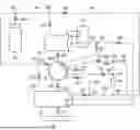
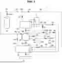
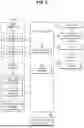
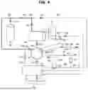
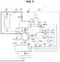
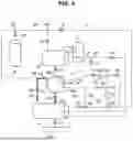
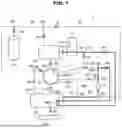
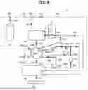
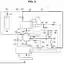

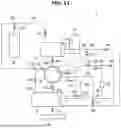
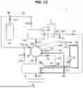
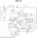
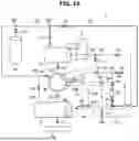
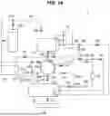
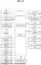
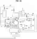
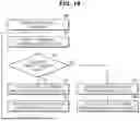

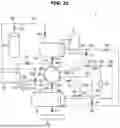
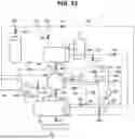
Sources:
- United States Patent and Trademark Office - verify current appl. status at the USPTO↗
Similar patent applications:
- » 20060230544
Drum type washing machine and controlling method thereof - » 20060191077
Washing machine and control method thereof - » 10719012
Washing machine and control method thereof - » 20060021154
Washing machine and control method thereof - » 20050034250
Heating apparatus of washing machine and control method thereof - » 20050081308
Washing machine and control method thereof - » 20050132503
Washing machine and control method thereof - » 20050144735
Washing machine and control method thereof - » 10878015
Washing machine and controlling method thereof - » 20060277690
Washing machine and control method thereof
Recent applications in this class:
Recent applications for this Assignee:
- » 20260173984 2026-06-18
SEMICONDUCTOR PACKAGE AND METHOD OF MANUFACTURING THE SEMICONDUCTOR PACKAGE - » 20260173976 2026-06-18
SEMICONDUCTOR PACKAGE AND METHOD FOR FABRICATING THE SAME - » 20260173969 2026-06-18
SEMICONDUCTOR PACKAGE AND METHOD OF MANUFACTURING SEMICONDUCTOR PACKAGE - » 20260173967 2026-06-18
SEMICONDUCTOR PACKAGE - » 20260173964 2026-06-18
SEMICONDUCTOR DEVICE - » 20260173949 2026-06-18
METHOD OF MANUFACTURING SEMICONDUCTOR PACKAGE - » 20260173929 2026-06-18
SEMICONDUCTOR CHIP, SEMICONDUCTOR PACKAGE INCLUDING THE SAME, AND METHOD OF FABRICATING THE SAME - » 20260173854 2026-06-18
SEMICONDUCTOR DEVICE INCLUDING WIRING STRUCTURE - » 20260173847 2026-06-18
INTEGRATED CIRCUIT INCLUDING HORIZONTALLY-EXTENDING MIDDLE-OF-LINE (MOL) STRUCTURE - » 20260173824 2026-06-18
VERTICALLY STACKED TEST STRUCTURE AND FABRICATION METHOD THEREFOR, AND SEMICONDUCTOR DEVICE HAVING VERTICALLY STACKED TEST STRUCTURE AND FABRICATION METHOD THEREFOR