GAS TURBINE COMBUSTOR
US20260168675A1
2026-06-18
19/382,387
2025-11-07
Smart Summary: A gas turbine combustor is designed to burn hydrogen fuel efficiently. It has a round outer casing that creates a space for combustion. A nozzle injects a mixture of air and fuel into this space to help with burning. An igniter is placed on the outside of the casing to start the combustion process. The nozzle is positioned at an angle to improve the mixing of air and fuel for better performance. 🚀 TL;DR
Abstract:
A combustor of a hydrogen gas turbine, comprising: an annular housing forming a combustion field; a fuel injection nozzle for injecting an air-fuel mixture of fuel and air toward the combustion field; and an igniter disposed on an outer periphery of the housing, wherein an axis of the fuel injection nozzle is disposed at an angle with respect to an axis of the housing.
Inventors:
- Shunsuke KASUGA 4 🇯🇵 Numazu-shi, Japan
- Yasushi TATEBAYASHI 5 🇯🇵 Fuji-shi, Japan
- Takahiro MINAMI 1 🇯🇵 Toyota-shi, Japan
Assignee:
- TOYOTA JIDOSHA KABUSHIKI KAISHA 26,758 🇯🇵 Toyota-shi, Japan
Applicant:
Interested in similar patents?
Get notified when new applications in this technology area are published.
Classification:
F23R3/286 » CPC main
Continuous combustion chambers using liquid or gaseous fuel characterised by the fuel supply having fuel-air premixing devices
F23R3/28 IPC
Continuous combustion chambers using liquid or gaseous fuel characterised by the fuel supply
Description
CROSS-REFERENCE TO RELATED APPLICATION
This application claims priority to Japanese Patent Application No. 2024-220773 filed on December 17, 2024. The disclosure of the above-identified application, including the specification, drawings, and claims, is incorporated by reference herein in its entirety.
BACKGROUND
1. Technical Field
The present disclosure relates to a gas turbine combustor.
2. Description of Related Art
Japanese Unexamined Patent Application Publication No. 2018-194210 (JP 2018-194210 A) discloses improving ignitability by providing an injection hole for auxiliary fuel in the vicinity of an igniter of a hydrogen gas turbine.
SUMMARY
Conventional gas turbine combustors are provided with an injection hole dedicated to ignition and an auxiliary fuel introduction passage, which complicates the structure. Such complication is not suitable, for example, for small gas turbines.
It is therefore an object of the present disclosure to provide a gas turbine combustor capable of improving ignitability at start-up without complicating the structure.
An aspect of the present application discloses a combustor of a hydrogen gas turbine. The combustor includes: an annular housing that provides a combustion field, a fuel injection nozzle that injects an air-fuel mixture of fuel and air toward the combustion field, and an igniter disposed at an outer periphery of the housing. An axis of the fuel injection nozzle is disposed with inclination with respect to an axis of the housing.
The fuel injection nozzle may include a first air injection port and a second air injection port arranged in an injection direction in the fuel injection nozzle, and a fuel injection port may be disposed between the first air injection port and the second air injection port.
An inclination angle of the inclination may be 45° to 70°.
The combustor of the hydrogen gas turbine may be of 10 kW to 90 kW.
According to the present disclosure, the fuel injected from the fuel injection nozzle is ejected toward the igniter, and therefore ignitability at start-up can be improved without complicating the structure.
BRIEF DESCRIPTION OF THE DRAWINGS
Features, advantages, and technical and industrial significance of exemplary embodiments of the disclosure will be described below with reference to the accompanying drawings, in which like signs denote like elements, and wherein:
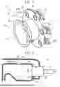
FIG. 1 is a perspective view illustrating the structure of a gas turbine combustor 10;
FIG. 2 is a cross-section illustrating the structure of the gas turbine combustor 10;
FIG. 3 is a perspective view of the fuel injection nozzle 20;
FIG. 4 is a cross-sectional view of a combustion injection nozzle 20;
FIG. 5A is a diagram illustrating a tilted flame; and
FIG. 5B is a diagram illustrating a tilted flame.
DETAILED DESCRIPTION OF EMBODIMENTS
1. Basic structure of gas turbine combustor
The gas turbine combustor of the present disclosure may be advantageously used in a gas turbine combustor that is fueled by hydrogen or a substance that is lighter in mass and has a higher combustion temperature than a hydrocarbon-based substance that has been previously used. FIG. 1 is a perspective view illustrating a gas turbine combustor 10 (only some members are illustrated for explanation), FIG. 2 is a view illustrating a periphery of one fuel injection nozzle 20 in the gas turbine combustor 10, FIG. 3 is an external perspective view of the fuel injection nozzle 20, and FIG. 4 is a view illustrating an internal structure of the fuel injection nozzle 20.
As can be seen from FIGS. 1 and 2, in the gas turbine combustor 10, the fuel injection nozzle 20 is installed 31a the opening of the housing 31 of the combustion chamber 30 defining the combustion field A. A compressed air PA flows into the fuel injection nozzle 20 from a compressor (not shown) connected to a turbine (not shown) through an annular compressed air supply ring 40 defined in an outer periphery of the combustion chamber 30. In addition, the fuel F flows from a fuel tank (not shown) through the fuel supply pipe 21, and the compressed air PA and the fuel F are mixed, and are discharged to the combustion field A as indicated by an arrow M and burned.
As can be seen from FIG. 1, a plurality of fuel injection nozzles 20 are arranged so as to circulate at predetermined intervals along the outer peripheral end portion of the housing 31, and an air-fuel mixture of fuel and air is discharged from each of the fuel injection nozzles 20 toward the combustion field A.
Further, as shown in FIG. 1, an igniter 50, which is an ignition device, is disposed at an outer peripheral portion of the housing 31, and is configured to ignite an air-fuel mixture of fuel and air discharged to the combustion field A so that a flame can be generated.
As shown in FIGS. 3 and 4, each of the fuel injection nozzles 20 has a substantially cylindrical peripheral wall portion 23 in which a flange 22 or the like is formed. Further, the respective fuel injection nozzles 20 are fitted to the opening 31a of the housing 31 such that the end face of the nozzle port 20a faces the combustion field A. In the nozzle port 20a of the fuel injection nozzle 20, a first air ejection port 20b is opened in a substantially central area thereof, and a slit-shaped (or point-like) second air ejection port 20c is formed so as to surround the periphery thereof. Further, in the nozzle port 20a of the fuel injection nozzle 20, a plurality of fuel injection ports 20d are arranged substantially uniformly between the first air ejection port 20b and the second air ejection port 20c.
The first air ejection port 20b, the fuel injection port 20d, and the second air ejection port 20c may be arranged concentrically in this order, and may be configured to inject the compressed air and the fuel more evenly. As can be seen from FIG. 4, the compressed air flow PA sent through the compressed air supply ring 40 flows into the air flow path from the air intake 40a. A portion of the compressed air flow PA is injected from the first air ejection port 20b and another portion from the second air ejection port 20c, respectively. Further, the fuel supplied through the fuel flow path 21a inside the fuel supply pipe 21 is injected from the fuel injection port 20d between the first air ejection port 20b and the second air ejection port 20c in a manner described later. The fuel injection amount is adjusted so that the combustion temperature becomes equal to or lower than 1500°C.
The diameter of the fuel injection port 20d is designed to be smaller than the extinguishing distance of the fuel in order to suppress flashback. Specifically, since the extinguishing distance of hydrogen is about 0.64 mm, when the fuel is hydrogen, the diameter of the fuel injection port 20d may be, for example, less than or equal to 0.6 mm.
In addition, in the present disclosure, the fuel injection nozzle 20 is configured to generate a flame F that is inclined at an angle θ in a circumferential direction with respect to a direction in which an axis O of an annular ring of the housing 31 extends. This is shown schematically in FIGS. 5A and 5B. That is, the fuel injection nozzle 20 injects an air-fuel mixture of fuel and air in the direction of the angle θ. Although a specific method for this purpose is not particularly limited, the direction of the fuel injection nozzle 20 itself may be inclined. Here, θ is the direction in which the concentration of the injected air-fuel mixture is highest. The specific value of the angle θ is not particularly limited, but may be 45° to 70°.
2. Effects
Hydrogen has a higher burning temperature than hydrocarbon-based fuels which have been generally used up to now, and NOx is easily generated. Therefore, in the combustor used in the hydrogen gas turbine, it is required to make the fuel concentration as uniform as possible in the mixing process from the introduction of the fuel and the air to the pre-combustion. This is to suppress a region in which the fuel concentration locally increases and the combustion temperature increases in the air-fuel mixture of the fuel and the air being formed. In particular, in the case of a small gas turbine, since the space between the air and the fuel inlet and the combustion site is reduced, it is preferable that the uniformity of the fuel in the air can be achieved as quickly as possible.
Therefore, in the gas turbine combustor 10 of the present embodiment, the first air ejection port 20b, the second air ejection port 20c, and the fuel injection port 20d are configured as described above. Since hydrogen and air are concentrated in a narrow range in the combustion chamber A on the downstream side of the fuel injection nozzle 20, the uniformity of the fuel in the air can be enhanced. On the other hand, in such a configuration, the high-temperature region is concentrated in a narrow range of the combustion chamber on the downstream side of the fuel injection nozzle, and therefore, it is difficult to supply an air-fuel mixture of hydrogen and oxygen to the periphery of the igniter, and thus it is difficult to ignite. Also, even when ignited, a flame is formed only immediately below the center of the fuel injection nozzle. In this case, the space other than the fuel injection nozzle is a useless space in which the flame is not formed. When this wasteful space can be effectively utilized, the gas turbine combustor can be miniaturized. In contrast, in the present disclosure, the flame formed from the fuel injection nozzle 20 is inclined in the circumferential direction. As a result, an air-fuel mixture of hydrogen and oxygen is injected toward the igniter 50 installed on the outer periphery of the housing 31. Since the air-fuel mixture reaches the outer peripheral side of the housing 31, the ignition performance by the igniter 50 can be enhanced without complicating the structure. As described above, since the space in the circumferential direction can be utilized, the gas turbine combustor can be miniaturized, and the effect is particularly remarkable in a small engine.
The configuration of the present embodiment is particularly a gas turbine using hydrogen as fuel, and is advantageously applied to a small gas turbine combustor of a small size, for example of 10 kW to 90 kW class, and more preferably of 10 kW to 60 kW class.
Claims
What is claimed is:1. A combustor of a hydrogen gas turbine, the combustor comprising:
an annular housing that provides a combustion field;
a fuel injection nozzle that injects an air-fuel mixture of fuel and air toward the combustion field; and
an igniter disposed at an outer periphery of the housing, wherein an axis of the fuel injection nozzle is disposed with inclination with respect to an axis of the housing.
2. The combustor according to claim 1, wherein the fuel injection nozzle includes a first air injection port and a second air injection port arranged in an injection direction in the fuel injection nozzle, and a fuel injection port is disposed between the first air injection port and the second air injection port.
3. The combustor according to claim 1, wherein an inclination angle of the inclination is 45° to 70°.
4. The combustor according to claim 1, wherein the combustor of the hydrogen gas turbine is of 10 kW to 90 kW.
Images & Drawings included:


Sources:
- United States Patent and Trademark Office - verify current appl. status at the USPTO↗
Similar patent applications:
- » 10440470
Fuel injection nozzle for gas turbine combustor, gas turbine combustor, and gas turbine - » 20230288068
Perforated plate for gas turbine combustor, gas turbine combustor, and gas turbine - » 20190368730
Resonant sound absorbing device of gas turbine combustor, gas turbine combustor including the same, and gas turbine - » 20190242581
Gas turbine combustor, gas turbine, and control method for gas turbine combustor - » 20180187891
Combustor nozzle, gas turbine combustor, gas turbine, cover ring, and combustor nozzle manufacturing method - » 10382500
Gas turbine combustor, combustion method of the gas turbine combustor, and method of remodeling a gas turbine combustor - » 20240133771
ABNORMALITY DETECTION SYSTEM FOR COMBUSTOR FOR GAS TURBINE, COMBUSTOR FOR GAS TURBINE AND GAS TURBINE, AND ABNORMALITY DETECTION METHOD FOR COMBUSTOR FOR GAS TURBINE - » 20240230471
ABNORMALITY DETECTION SYSTEM FOR COMBUSTOR FOR GAS TURBINE, COMBUSTOR FOR GAS TURBINE AND GAS TURBINE, AND ABNORMALITY DETECTION METHOD FOR COMBUSTOR FOR GAS TURBINE - » 20170219211
Gas turbine combustor, gas turbine, control device, and control method - » 10464499
Gas turbine combustor, gas turbine, and jet engine
Recent applications in this class:
- » 20260168674 2026-06-18
GAS TURBINE ENGINE INCLUDING HYDROGEN-COMPATIBLE FUEL-AIR MIXER WITH MULTI-JET MIXING TUBE - » 20260160420 2026-06-11
HYDROGEN CAPABLE FUEL INJECTOR AND ASSEMBLY - » 20260146739 2026-05-28
COMBUSTOR WITH BAFFLE - » 20260139837 2026-05-21
COMBUSTION NOZZLE - » 20260110433 2026-04-23
COMBUSTOR NOZZLE, AND COMBUSTOR AND GAS TURBINE INCLUDING SAME - » 20260104166 2026-04-16
BURNER, COMBUSTOR PROVIDED WITH SAME, AND GAS TURBINE PROVIDED WITH COMBUSTOR - » 20260092706 2026-04-02
Turbine Engine and Fuel Nozzle Assembly Therefor - » 20260092705 2026-04-02
GAS TURBINE ENGINE AND FUEL INJECTOR ASSEMBLY THEREFOR - » 20260085837 2026-03-26
COAXIALLY STAGED BURNER FOR LOW-EMISSION COMBUSTION CHAMBER OF DUAL-FUEL GAS TURBINE UTILIZING GASEOUS AND LIQUID FUELS - » 20260078905 2026-03-19
TURBINE ENGINE WITH COMBUSTION SECTION AND FUEL PASSAGE THAT SUPPLIES HYDROGEN-CONTAINING FUEL TO COMBUSTION SECTION
Recent applications for this Assignee:
- » 20260173028 2026-06-18
IN-VEHICLE DEVICE, VEHICLE, SYSTEM, NON-TRANSITORY STORAGE MEDIUM, AND PROFILE SETTING METHOD - » 20260172883 2026-06-18
SYSTEM - » 20260171878 2026-06-18
MOTOR UNIT - » 20260171857 2026-06-18
STATOR - » 20260171856 2026-06-18
STATOR CORE - » 20260171666 2026-06-18
CONTROL DEVICE AND CONTROL METHOD - » 20260171548 2026-06-18
ENERGY STORAGE DEVICE - » 20260171546 2026-06-18
HEAT MANAGEMENT SYSTEM, AND MANUFACTURING METHOD FOR HEAT MANAGEMENT SYSTEM - » 20260171537 2026-06-18
ENERGY STORAGE DEVICE - » 20260171535 2026-06-18
ELECTRODE ASSEMBLY