KNIFE SHARPENING MECHANISM WITH AN ADJUSTABLE SHARPENING ANGLE AND AN ELECTRIC KNIFE SHARPENER
US20260175344A1
2026-06-25
19/020,033
2025-01-14
Smart Summary: A knife sharpening mechanism allows users to sharpen knives easily and effectively. It features an adjustable angle to suit different types of knives. The system includes a driving wheel and sets of driven wheels that work together with an abrasive belt. When the driving wheel spins, it moves the abrasive belt to sharpen the knife. This design makes it simple to change the sharpening angle for various cutting tools. 🚀 TL;DR
Abstract:
A knife sharpening mechanism with an adjustable sharpening angle and an electric knife sharpener, comprising: an angle adjuster, a bracket, a driving wheel, driven wheel sets and an abrasive belt; at a bottom interior of the bracket is provided with the driving wheel, an upper end of an interior of the bracket is symmetrically provided with driven wheel sets, a driven wheel set is provided at a position diagonally above a side of driving wheel at a lower end of the bracket, the abrasive belt is set covering the driving wheel and the driven wheel sets, and the rotation of the abrasive belt is driven by the driving wheel to realize sharpening of a cutting tool, and at a front end of the bracket is provided with an angle adjuster to realize adjustment of the grinding angle of the tool to adapt to the grinding needs of different tools.
Applicant:
Interested in similar patents?
Get notified when new applications in this technology area are published.
Classification:
B24B3/54 » CPC main
Sharpening cutting edges, e.g. of tools; Accessories therefor, e.g. for holding the tools of cutting blades of hand or table knives
B24B41/066 » CPC further
Component parts such as frames, beds, carriages, headstocks; Work supports, e.g. adjustable steadies adapted for supporting work in the form of tools, e.g. drills
B24B41/06 IPC
Component parts such as frames, beds, carriages, headstocks Work supports, e.g. adjustable steadies
Description
1. TECHNICAL FIELD
The invention belongs to the technical field of knife grinder, specifically relates to a knife sharpening mechanism with an adjustable sharpening angle and an electric knife sharpener.
2. BACKGROUND ART
People cannot live without knives, especially household kitchen knives, fruit knives and other board-shaped knives. If the knife is blunt, it needs to be sharpened, most of the traditional sharpening method use a block-shaped brick or waste grinding wheel for manual sharpening, which is laborious and time-consuming, and also contaminate the kitchen and affects sanitation. There are also people take the knife with a hand to sharpen the knife directly on an ordinary grinder or a simple grinder, often leading to sparks flying in all directions, and hurting the hand accidentally, there is a potential safety hazard.
The improved technical solution aimed at the prior art includes an electric multifunctional fixed-angle knife sharpener disclosed in patent number CN202122004387.6, which comprises an abrasive belt for grinding, an electric motor for driving the abrasive belt to act, a belt wheel transmission mechanism and a machine shell. The belt wheel transmission mechanism comprises a driving U-shaped wheel driven by the electric motor to rotate, and a driven U-shaped wheel; the driven U-shaped wheel is arranged on a rotatable U-shaped groove frame through a first pin shaft; an end of the U-shaped groove frame adjacent to the driving U-shaped wheel is provided with a hinged shaft to achieve rotation, an other end thereof is provided with a button pin that can be unlocked or locked and equipped with a pin hole; the electric multifunctional fixed-angle knife sharpener has the characteristics that the structure is compact, the abrasive belt is convenient to replace, the grinding tool template is easy to operate, and is convenient to use at home; however, the above solution also has shortcomings: the angle of the tool cannot be adjusted according to the type of tool and the grinding situation, which leads to the grinding of the knife is not sharp, and the effect is poor;
Therefore, for the technical problems described above, there is an urgent need for a knife sharpening mechanism and electric knife sharpener with adjustable sharpening angle.
3. SUMMARY OF THE INVENTION
The technical problem to be solved by the invention is to overcome defects of the prior art, and to provide a knife sharpening mechanism with an adjustable sharpening angle and an electric knife sharpener.
In order to solve the above technical problem, a technical solution provided by the invention is a knife sharpening mechanism with an adjustable sharpening angle, comprising:
an angle adjuster, a bracket, a driving wheel, driven wheel sets and an abrasive belt; at a bottom interior of the bracket is provided with the driving wheel, at an upper end of an interior of the bracket is symmetrically provided with driven wheel sets, a driven wheel set is provided at a position diagonally above a side of the driving wheel at a lower end of the bracket, the abrasive belt is set covering the driving wheel and the driven wheel sets, and the rotation of the abrasive belt is driven by the driving wheel to realize sharpening of a cutting tool, and at a front end of the bracket is provided with an angle adjuster to realize adjustment of the grinding angle of the tool to adapt to the grinding needs of different tools.
As an improvement, the bracket includes a front bracket and a rear bracket set at a rear side of the front bracket, the driving wheel, driven wheel sets and abrasive belt are all located between the front bracket and the rear bracket, and two ends of a wheel axle of each driven wheel set are connected to the front bracket and the rear bracket, respectively, and a servomotor is provided at a front end of a lower end of the front bracket, and a rotating shaft of the servomotor is provided to pass through the front bracket and extends between the front bracket and the rear bracket, and the driving wheel is set on the rotating shaft of the servomotor.
As an improvement, a tensioning mechanism is provided between the front bracket and rear bracket to cooperate with the abrasive belt, the tensioning mechanism is located diagonally above a side of the driving wheel and is set opposite to the driven wheel set at a lower end of the front bracket;
the tensioning mechanism includes a fixing plate, a wheel frame, a guide rod and a spring; one end of the fixing plate is set on the rear bracket, sliding grooves are provided on both of an inner wall of the front bracket and an inner wall of the rear bracket, a mounting groove is provided at a top of the sliding groove on the front bracket, another end of the fixing plate is placed in the mounting groove; a middle of the fixing plate is provided with a sliding hole; the guide rod is slidably set inside the sliding hole, a lower end of the guide rod is provided with the wheel frame, and in the wheel frame is provided with a tensioning wheel, the tensioning wheel and abrasive belt cooperate in a rolling manner so that the abrasive belt is in a state of tension; two sides of the wheel frame are located in the sliding groove, the spring is sleeved on the guide rod and is located between the wheel frame and the fixing plate, an upper end of the guide rod is rotatably provided with a pull rod, above the fixing plate on the rear bracket is provided with an adjusting groove, one end of the pull rod extends out from the adjusting groove, and an upper end of the adjusting groove is provided with a limiting groove.
As an improvement, the angle adjuster comprises a knob, a fixing shaft, cams, shaft sleeves, shaft rods, connecting arms and a tension spring; the fixing shaft is provided at a front end of the front bracket, the fixing shaft is rotatably provided with a knob, the knob is provided with two cams, a plurality of clamping grooves are provided on circumferences of wheels of the cams; shaft rods are provided symmetrically at a front end of the front bracket, the shaft rods are rotatably provided with shaft sleeves, and each shaft sleeve is provided with a connecting arm; two connecting arms are staggered, and each connecting arm cooperates with one of the corresponding cams, one end of each connecting arm is provided with an arc-shaped protrusion, and the arc-shaped protrusion cooperates with the clamping groove for positioning the connecting arm; other ends of the connecting arms extend to two sides of the front bracket respectively, an end of each connecting arm that extends to a side of the front bracket is provided with a pressure plate, a V-shaped placing cavity is formed between each pressure plate and the abrasive belt; one end of each connecting arm provided with the arc-shaped protrusion is provided with a hanging ring, and both ends of the tension spring are respectively connected to two hanging rings so that the arc-shaped protrusion is tightly attached to an outer edge of the cam to achieve angle adjustment by rotating the knob.
As an improvement, a chamber is provided at the position where the pressure plate and connecting arm are connected, an upper end of the chamber extends out of the pressure plate and connecting arm, one end of the chamber extends out of the pressure plate, in the chamber is rotatably provided with a roller, an upper end of the roller protrudes out of the chamber, one end of the chamber extending out of the pressure plate is provided with an end cover, and the roller is rotatably connected with the end cover.
An electric knife sharpener, characterized in that it comprises a knife sharpening mechanism with an adjustable sharpening angle as described in any one of claims 1 to 5;
It also includes a housing, a control mechanism and a grinding mechanism, the knife sharpening mechanism with an adjustable sharpening angle is set at a rear end of the housing, plug-in slots are symmetrically provided on two sides of an upper end of the housing, and the plug-in slots are located on both sides of the front bracket; in the plug-in slot is provided with the grinding mechanism, and a control mechanism is provided at a front end of the housing.
As an improvement, the control mechanism includes a controller and a power adapter; the power adapter is set at a front end of an interior of the housing, the front end of the housing is provided with a jack that cooperates with the power adapter, and the upper end of the housing is provided with the controller.
As an improvement, an upper end of a central part of the housing is provided with an upper housing, notches are provided at an upper end and two sides of the upper housing, the upper housing is covered on an outer side of the knob, a rear end of the upper housing is connected to the front bracket, an upper portion of the knob extends out from the notch at the upper end of the upper housing, and one end of the connecting arms extends out from the notches at sides of the upper housing.
As an improvement, a rear end of the housing is rotatably provided with a door via a shaft, the door is located at a rear side of the rear bracket to protect the knife sharpening mechanism with an adjustable sharpening angle, an upper end of the door is provided with an upper slot, a top cover is provided on top of the front bracket and rear bracket, a rear end of the top cover is connected to fit with the upper slot; a front end of the top cover is placed on the upper housing; the door is symmetrically provided with V-shaped grooves, the V-shaped grooves and V-shaped placing cavities mating for placing a tool.
As an improvement, the grinding mechanism comprises a grinding frame and a plate body; in the upper slot is provided with the grinding frame, an extension plate is provided on one side of an upper end of the grinding frame, the extension plate extends in the direction of the abrasive belt and forms a protection for the pressure plate; one side of the grinding frame is provided with a groove, and in the groove is rotatably provided with the plate body via a shaft, and one side of the plate body is provided with an abrasive plate.
Compared with the prior art, the invention has the following advantages:
1. the abrasive belt is set covering the driving wheel and driven wheel sets, the driven wheel sets enable the abrasive belt to form a certain inclined angle, the front end of the bracket is equipped with an angle adjuster to realize adjustment of the tool grinding angle, in order to adapt to the grinding needs of different tools;
the connecting arms extend to both sides of the front bracket respectively, an end of each connecting arm that extends to a side of the front bracket is provided with a pressure plate, the pressure plate on the connecting arm and the abrasive belt forms a certain angle, and the angle between the connecting arm and the abrasive belt can be adjusted by adjusting the knob, to form different angles to adapt to different cutting edge angles of the tool, so as to achieve the effect of sharpening the knife to enhance the degree of sharpness; and the abrasive belt on left and right sides of the front bracket can be used to grind the tool, more convenient to use;
2. the knob is provided with two cams, a plurality of clamping grooves are provided on circumferences of wheels of the cams; one end of each connecting arm is provided with an arc-shaped protrusion, and the arc-shaped protrusion cooperates with the clamping groove; both ends of the tension spring are respectively connected to two hanging rings so that the arc-shaped protrusion is tightly attached to an outer edge of the cam to achieve angle adjustment by rotating the knob;
3. a tensioning mechanism is provided, the spring is sleeved on the guide rod and is located between the wheel frame and the fixing plate, so that the force of the spring is applied to the wheel frame, so that the tensioning wheel is tightly attached to the abrasive belt and the abrasive belt has a certain tension;
sliding grooves are provided on both of an inner wall of the front bracket and an inner wall of the rear bracket, two sides of the wheel frame are located in the sliding groove, an upper end of the guide rod is rotatably provided with a pull rod, above the fixing plate on the rear bracket is provided with an adjusting groove, one end of the pull rod extends out from the adjusting groove, and an upper end of the adjusting groove is provided with a limiting groove, so that the tensioning wheel can be made to move along the sliding groove, and then the pull rod is fixed to the limiting groove, then the tensioning wheel is away from the abrasive belt, and the abrasive belt is no longer tensioned, and the abrasive belt can be replaced;
4. both sides of the housing are equipped with abrasive plates that can be turned over and adjusted, which can be turned over and opened for grinding different tools, and can also be rotated and stowed in the groove, it is more convenient to use.
4. BRIEF DESCRIPTION OF ACCOMPANY DRAWINGS
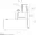
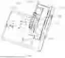
FIG. 1 is a side view of a knife sharpening mechanism with an adjustable sharpening angle and an electric knife sharpener provided by the invention;
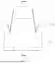
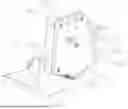
FIG. 2 is a rear view of a knife sharpening mechanism with an adjustable sharpening angle and an electric knife sharpener provided by the invention;
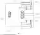
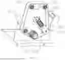
FIG. 3 is a top view of a knife sharpening mechanism with an adjustable sharpening angle and an electric knife sharpener provided by the invention;
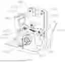
FIG. 4 is a three-dimensional structural diagram of a knife sharpening mechanism with an adjustable sharpening angle and an electric knife sharpener provided by the invention;
FIG. 5 is a first disassembled state diagram of a knife sharpening mechanism with an adjustable sharpening angle and an electric knife sharpener provided by the invention;
FIG. 6 is a second disassembled state diagram of a knife sharpening mechanism with an adjustable sharpening angle and an electric knife sharpener provided by the invention;
FIG. 7 is a third disassembled state diagram of a knife sharpening mechanism with an adjustable sharpening angle and an electric knife sharpener provided by the invention;
FIG. 8 is a fourth disassembled state diagram of a knife sharpening mechanism with an adjustable sharpening angle and an electric knife sharpener provided by the invention;
FIG. 9 is a reference diagram of a state of use of the abrasive plate of a knife sharpening mechanism with an adjustable sharpening angle and an electric knife sharpener provided by the invention;
FIG. 10 is schematic diagram of a knife sharpening mechanism with an adjustable sharpening angle of a knife sharpening mechanism with an adjustable sharpening angle and an electric knife sharpener provided by the invention;
FIG. 11 is a sectional view at A-A in FIG. 2;
FIG. 12 is a sectional view at B-B in FIG. 1;
FIG. 13 is a partially enlarged view of C in FIG. 12;
FIG. 14 is a partially enlarged view of D in FIG. 11.
As shown in the accompany drawings:
-
- 100 driving wheel,
- 200 driven wheel set,
- 300 abrasive belt,
- 401 front bracket, 402 rear bracket, 403 servomotor,
- 501 fixing plate, 502 wheel frame, 503 guide rod, 504 spring, 505 sliding groove, 506 mounting groove, 507 sliding hole, 508 tensioning wheel, 509 pull rod, 510 adjusting groove, 511 limiting groove,
- 601 knob, 602 fixing shaft, 603 cam, 604 shaft sleeve, 605 shaft rod, 606 connecting arm, 607 tension spring, 608 clamping groove, 609 arc-shaped protrusion, 610 pressure plate, 611 V-shaped placing cavity, 612 hanging ring, 613 chamber, 614 roller, 615 end cover,
- 701 housing, 702 plug-in slot, 703 upper housing, 704 notch, 705, door, 706 upper slot, 707 top cover, 708 V-shaped groove,
- 801 controller, 802 power adapter, 803 jack,
- 901 grinding frame, 902 plate body, 903 extension plate, 904 groove, 905 abrasive plate.
5. SPECIFIC EMBODIMENT OF THE INVENTION
In order to make the objects, technical solutions and advantages of the embodiments of the present invention clearer, the technical solutions in the embodiments of the invention will be clearly and completely described below with reference to the drawings in the embodiments of the invention, and it is obvious that the described embodiments are some, but not all, embodiments of the invention. The components of embodiments of the invention generally described and illustrated in the figures herein may be arranged and designed in a wide variety of different configurations.
With reference to FIG. 1 to FIG. 14, a knife sharpening mechanism with an adjustable sharpening angle, comprising:
an angle adjuster, a bracket, a driving wheel 100, driven wheel sets 200 and an abrasive belt 300; at a bottom interior of the bracket is provided with the driving wheel 100, at an upper end of an interior of the bracket is symmetrically provided with driven wheel sets 200, a driven wheel set 200 is provided at a position diagonally above a side of the driving wheel 100 at a lower end of the bracket, the abrasive belt 300 is set covering the driving wheel 100 and the driven wheel sets 200, and the rotation of the abrasive belt 300 is driven by the driving wheel 100 to realize sharpening of a cutting tool, and at a front end of the bracket is provided with an angle adjuster to realize adjustment of the grinding angle of the tool to adapt to the grinding needs of different tools.
As an improvement, the bracket includes a front bracket 401 and a rear bracket 402 set at a rear side of the front bracket, the driving wheel 100, driven wheel sets 200 and abrasive belt 300 are all located between the front bracket 401 and the rear bracket 402, and two ends of a wheel axle of each driven wheel set 200 are connected to the front bracket 401 and the rear bracket 402, respectively, and a servomotor 403 is provided at a front end of a lower end of the front bracket 401, and a rotating shaft of the servomotor 403 is provided to pass through the front bracket 401 and extends between the front bracket 401 and the rear bracket 402, and the driving wheel 100 is set on the rotating shaft of the servomotor 403.
A tensioning mechanism is provided between the front bracket 401 and rear bracket 402 to cooperate with the abrasive belt 300, the tensioning mechanism is located diagonally above a side of the driving wheel 100 and is set opposite to the driven wheel set 200 at a lower end of the front bracket 401;
the tensioning mechanism includes a fixing plate 501, a wheel frame 502, a guide rod 503 and a spring 504; one end of the fixing plate 501 is set on the rear bracket 402, sliding grooves 505 are provided on both of an inner wall of the front bracket 401 and an inner wall of the rear bracket 402, a mounting groove 506 is provided at a top of the sliding groove 50 on the front bracket 401, an other end of the fixing plate 501 is placed in the mounting groove 506; a middle of the fixing plate 501 is provided with a sliding hole 507; the guide rod 503 is slidably set inside the sliding hole 507, a lower end of the guide rod 503 is provided with the wheel frame 502, and in the wheel frame 502 is provided with a tensioning wheel 508, the tensioning wheel 508 and abrasive belt 300 cooperate in a rolling manner so that the abrasive belt 300 is in a state of tension; two sides of the wheel frame 502 are located in the sliding groove 505, the spring 504 is sleeved on the guide rod 503 and is located between the wheel frame 502 and the fixing plate 501, an upper end of the guide rod 503 is rotatably provided with a pull rod 509, and the width of the pull rod 509 is greater than the thickness thereof; above the fixing plate 501 on the rear bracket 402 is provided with an adjusting groove 510, one end of the pull rod 509 extends out from the adjusting groove 510, and an upper end of the adjusting groove 510 is provided with a limiting groove 511.
Pulling the pull rod 509 to move along the adjusting groove 510 can pull the wheel frame 502 to move along the sliding groove 505 until the pull rod 509 reaches the limiting groove 511, and then rotate the pull rod 509; since the width of the pull rod 509 is greater than the thickness thereof, so that the pull rod 509 can stay in the limiting groove 511, and so that the tensioning wheel 508 is away from the abrasive belt 300, and the abrasive belt 300 is no longer tensioned, and the abrasive belt 300 can be replaced.
The angle adjuster comprises a knob 601, a fixing shaft 602, cams 603, shaft sleeves 604, shaft rods 605, connecting arms 606 and a tension spring 607; the fixing shaft 602 is provided at a front end of the front bracket 401, the fixing shaft 602 is rotatably provided with a knob 601, the knob 601 is provided with two cams 603, a plurality of clamping grooves 608 are provided on circumferences of wheels of the cams 603; shaft rods 605 are provided symmetrically at a front end of the front bracket 401, the shaft rods 605 are rotatably provided with shaft sleeves 604, and each shaft sleeve 604 is provided with a connecting arm 606; two connecting arms 606 are staggered, and each connecting arm 606 cooperates with one of the corresponding cams 603, one end of each connecting arm 606 is provided with an arc-shaped protrusion 609, and the arc-shaped protrusion 609 cooperates with the clamping groove 608 for positioning the connecting arm 606; other ends of the connecting arms 606 extend to two sides of the front bracket 401 respectively, an end of each connecting arm 606 that extends to a side of the front bracket 401 is provided with a pressure plate 610, a V-shaped placing cavity 611 is formed between each pressure plate 610 and the abrasive belt 300; one end of each connecting arm 606 provided with the arc-shaped protrusion 609 is provided with a hanging ring 612, and both ends of the tension spring 607 are respectively connected to two hanging rings 612 so that the arc-shaped protrusion 609 is tightly attached to an outer edge of the cam 603 to achieve angle adjustment by rotating the knob 601.
A chamber 613 is provided at the position where the pressure plate 610 and connecting arm 606 are connected, an upper end of the chamber 613 extends out of the pressure plate 610 and connecting arm 606, one end of the chamber 613 extends out of the pressure plate 610, in the chamber 613 is rotatably provided with a roller 614, an upper end of the roller 614 protrudes out of the chamber 613, one end of the chamber 613 extending out of the pressure plate 610 is provided with an end cover 615, and the roller 614 is rotatably connected with the end cover 615.
Specifically, put the tool into the V-shaped placing cavity 611, and make the tool blade upward, the back of the knife is placed on the roller 614, a side surface of the tool is attached to a side of the pressure plate 610; when the knob 601 rotates, the cams 603 push the arc-shaped protrusions 609 on the connecting arms 606, the connecting arms 606 will rotate with the fixing shaft 602 as a rotating shaft, which further drives the pressure plate 610 and the tool to approach the direction of the abrasive belt 300, so that the tool blade is attached to the abrasive belt 300, to achieve the grinding of the tool; on the other hand, it also realizes the adjustment of the grinding angle of the tool, and can be adapted to the grinding needs of different tools; a plurality of clamping grooves 608 are provided on circumferences of wheels of the cams 603; the arc-shaped protrusion 611 cooperates with the clamping groove 608; both ends of the tension spring 607 are respectively connected to two hanging rings 612, so that the connecting arms 606 can be pulled, and the arc-shaped protrusion 611 can stay in the clamping groove 608, therefore, on the one hand, the connecting arms 606 can be located, that is, to fix the position of the pressure plate 610, so as to realize grinding of the tool at a fixed angle; in addition, the tension spring 607 can ensure that the arc-shaped protrusions 611 are attached closely to an outer edge of the cams 603, so as to achieve that the pressure plate 610 follows the rotation of the cams 603 to achieve angle adjustment; in another aspect, the design of the roller 614 makes it possible to push the tool back and forth, thus realizing the grinding of the entire blade of the tool.
An electric knife sharpener, characterized in that it comprises a knife sharpening mechanism with an adjustable sharpening angle as described in any one of claims 1 to 5;
it also includes a housing 701, a control mechanism and a grinding mechanism, the knife sharpening mechanism with an adjustable sharpening angle is set at a rear end of the housing 701, plug-in slots 702 are symmetrically provided on two sides of an upper end of the housing 701, and the plug-in slots 702 are located on both sides of the front bracket 401; in the plug-in slot 702 is provided with the grinding mechanism, and a control mechanism is provided at a front end of the housing 701.
The control mechanism includes a controller 801 and a power adapter 802; the power adapter 802 is set at a front end of an interior of the housing 701, the front end of the housing 701 is provided with a jack 803 that cooperates with the power adapter 802, and the upper end of the housing 701 is provided with the controller 801; the controller 801, the power adapter 802, and the servomotor 403 are connected to each other by lines, and the on-off of the power supply and the on-off of the servomotor 403 are controlled by the controller 801.
An upper end of a central part of the housing 701 is provided with an upper housing 703, notches 704 are provided at an upper end and two sides of the upper housing 703, the upper housing 703 is covered on an outer side of the knob 601, a rear end of the upper housing 703 is connected to the front bracket 401, an upper portion of the knob 601 extends out from the notch 704 at the upper end of the upper housing 703, and one end of the connecting arms 606 extends out from the notches 704 at sides of the upper housing 703.
A rear end of the housing 701 is rotatably provided with a door 705 via a shaft, the door 705 is located at a rear side of the rear bracket 402 to protect the knife sharpening mechanism with an adjustable sharpening angle, which is also easy to open the door 705 to change the abrasive belt 300 or to carry out internal maintenance; an upper end of the door 705 is provided with an upper slot 706, a top cover 707 is provided on top of the front bracket 401 and rear bracket 402, a rear end of the top cover 707 is connected to fit with the upper slot 706; a front end of the top cover 707 is placed on the upper housing 703; the door 705 is symmetrically provided with V-shaped grooves 708, the V-shaped grooves 708 and V-shaped placing cavities 611 mating for placing a tool.
The grinding mechanism comprises a grinding frame 901 and a plate body 902; in the upper slot 706 is provided with the grinding frame 901, an extension plate 903 is provided on one side of an upper end of the grinding frame 901, the extension plate 903 extends in the direction of the abrasive belt 300 and forms a protection for the pressure plate 610; one side of the grinding frame 901 is provided with a groove 904, and in the groove 904 is rotatably provided with the plate body 902 via a shaft, and one side of the plate body 902 is provided with an abrasive plate 905; when the plate body 902 is turned and flipped over, one side of the plate body 902 rests on the extension plate 903 so that the abrasive plate 905 is exposed so that different tools can be sharpened during use.
When the invention is in its specific embodiment,
when in use, by plugging the power supply plug into the power adapter 802, and then using the controller 801 to turn on the power supply of the equipment and turn on the servomotor 403, the servomotor 403 rotates and drives the abrasive belt 300 to rotate through the driving wheel 100, and then the back of the tool is put into the V-shaped groove 708 and the V-shaped placing cavity 611; then the knob 601 is rotated by the hand, and the rotation of the knob 601 drives the cams 603 to rotate, because two ends of the tension spring 607 are respectively connected with the hanging rings 612 on two connecting arms 606, the arc-shaped protrusion 609 is tightly attached to an outer edge of the cams 603, when the cams 603 rotate, one end of the connecting arms 606, which are attached to the cams 603, moves up and down along with the cams 603, so that the whole connecting arms 606 rotate with the shaft rod 605 as a rotating shaft, thereby realizing angle adjustment between the pressure plate 610 on the connecting arm 606 and the abrasive belt 300, when the pressure plate 610 is close to the abrasive belt 300, the tool is pushed to approach the abrasive belt 300 and is attached to the abrasive belt 300, to realize grinding of the tool, and the back of the tool is positioned on the roller 614, so that the tool can be pushed to move back and forth, and realize the grinding of the whole blade of the tool;
when it is necessary to grind other tools, the plate body 902 can be turned over so that one side of the plate body 902 is placed on the extension plate 903 to form a support for the plate body 902, at which time the abrasive plate 905 is located on an upper part, so that it is possible to grind different tools on the abrasive plate 905;
when replacing the abrasive belt 300, opening the rear door 705, pulling the pull rod 509 to move along the adjusting groove 510, the wheel frame 502 can be pulled to move along the sliding groove 505 until the pull rod 509 reaches the limiting groove 511, and then rotating the pull rod 509, because the width of the pull rod 509 is greater than the thickness thereof, so that the pull rod 509 can stay in the limiting groove 511, so that the tensioning wheel 508 is away from the abrasive belt 300, and the abrasive belt 300 is no longer tensioned, and the abrasive belt 300 can be replaced; after the replacement is completed, the pull rod 509 is pulled so that it is detached from the limiting groove 511, and the pull rod 509 will move down along the adjusting groove 510 under the action of the spring 504, and the wheel frame 502 will move down along the sliding groove 505 until the tensioning wheel 508 is pressed against the abrasive belt 300 to make the abrasive belt 300 under tension.
In the description of the embodiments of the invention, it should be noted that, if the terms “center”, “on”, “below”, “left”, “right”, “vertical”, “horizontal”, “inner”, “outer”, etc. indicate orientations or positional relationships based on the orientations or positional relationships shown in the drawings or the orientations or positional relationships that the products of the invention are usually placed in when used, the orientations or positional relationships are only used for convenience of describing the invention and simplifying the description, but the terms do not indicate or imply that the devices or elements indicated must have specific orientations, be constructed in specific orientations, and operate, and therefore, should not be construed as limiting the invention. Furthermore, the terms “first”, “second”, “third” and the like are used solely to distinguish one from another and are not to be construed as indicating or implying relative importance.
Furthermore, the terms “horizontal”, “vertical”, “overhang” and the like do not require that the components be absolutely horizontal or overhang, but may be slightly inclined. For example, “horizontal” merely means that the direction is more horizontal than “vertical” and does not mean that the structure must be perfectly horizontal, but may be slightly inclined.
In the description of the embodiments of the invention, “a plurality” represents at least 2.
In the description of the embodiments of the invention, it should be further noted that unless otherwise explicitly stated or limited, the terms “arranged”, “mounted”, and “connected” should be interpreted broadly, and may be, for example, fixedly connected, detachably connected, or integrally connected; can be mechanically or electrically connected; they may be connected directly or indirectly through intervening media, or they may be interconnected between two elements. The specific meanings of the above terms in the invention can be understood by those skilled in the art according to specific situations.
The invention and its embodiments have been described above, but the description is not limited thereto; only one embodiment of the invention is shown in the drawings, and the actual structure is not limited thereto. In general, it is to be understood by those skilled in the art that non-creative design of structural forms and embodiments that are similar to the technical solutions without departing from the spirit of the invention shall all fall within the protective scope of the invention.
Claims
1. A knife sharpening mechanism with an adjustable sharpening angle, comprising:
an angle adjuster, a bracket, a driving wheel, driven wheel sets and an abrasive belt; at a bottom interior of the bracket is provided with the driving wheel, at an upper end of an interior of the bracket is symmetrically provided with driven wheel sets, a driven wheel set is provided at a position diagonally above a side of the driving wheel at a lower end of the bracket, the abrasive belt is set covering the driving wheel and the driven wheel sets, and the rotation of the abrasive belt is driven by the driving wheel to realize sharpening of a cutting tool, and at a front end of the bracket is provided with an angle adjuster to realize adjustment of the grinding angle of the tool to adapt to the grinding needs of different tools.
2. The knife sharpening mechanism with an adjustable sharpening angle of claim 1, wherein the bracket includes a front bracket and a rear bracket set at a rear side of the front bracket, the driving wheel, driven wheel sets and abrasive belt are all located between the front bracket and the rear bracket, and two ends of a wheel axle of each driven wheel set are connected to the front bracket and the rear bracket, respectively, and a servomotor is provided at a front end of a lower end of the front bracket, and a rotating shaft of the servomotor is provided to pass through the front bracket and extends between the front bracket and the rear bracket, and the driving wheel is set on the rotating shaft of the servomotor.
3. The knife sharpening mechanism with an adjustable sharpening angle of claim 2, wherein a tensioning mechanism is provided between the front bracket and rear bracket to cooperate with the abrasive belt, the tensioning mechanism is located diagonally above a side of the driving wheel and is set opposite to the driven wheel set at a lower end of the front bracket;
the tensioning mechanism includes a fixing plate, a wheel frame, a guide rod and a spring; one end of the fixing plate is set on the rear bracket, sliding grooves are provided on both of an inner wall of the front bracket and an inner wall of the rear bracket, a mounting groove is provided at a top of the sliding groove on the front bracket, another end of the fixing plate is placed in the mounting groove; a middle of the fixing plate is provided with a sliding hole; the guide rod is slidably set inside the sliding hole, a lower end of the guide rod is provided with the wheel frame, and in the wheel frame is provided with a tensioning wheel, the tensioning wheel and abrasive belt cooperate in a rolling manner so that the abrasive belt is in a state of tension; two sides of the wheel frame are located in the sliding groove, the spring is sleeved on the guide rod and is located between the wheel frame and the fixing plate, an upper end of the guide rod is rotatably provided with a pull rod, above the fixing plate on the rear bracket is provided with an adjusting groove, one end of the pull rod extends out from the adjusting groove, and an upper end of the adjusting groove is provided with a limiting groove.
4. The knife sharpening mechanism with an adjustable sharpening angle of claim 2, wherein the angle adjuster comprises a knob, a fixing shaft, cams, shaft sleeves, shaft rods, connecting arms and a tension spring; the fixing shaft is provided at a front end of the front bracket, the fixing shaft is rotatably provided with a knob, the knob is provided with two cams, a plurality of clamping grooves are provided on circumferences of wheels of the cams; shaft rods are provided symmetrically at a front end of the front bracket, the shaft rods are rotatably provided with shaft sleeves, and each shaft sleeve is provided with a connecting arm; two connecting arms are staggered, and each connecting arm cooperates with one of the corresponding cams, one end of each connecting arm is provided with an arc-shaped protrusion, and the arc-shaped protrusion cooperates with the clamping groove for positioning the connecting arm; other ends of the connecting arms extend to two sides of the front bracket respectively, an end of each connecting arm that extends to a side of the front bracket is provided with a pressure plate, a V-shaped placing cavity is formed between each pressure plate and the abrasive belt; one end of each connecting arm provided with the arc-shaped protrusion is provided with a hanging ring, and both ends of the tension spring are respectively connected to two hanging rings so that the arc-shaped protrusion is tightly attached to an outer edge of the cam to achieve angle adjustment by rotating the knob.
5. The knife sharpening mechanism with an adjustable sharpening angle of claim 4, wherein a chamber is provided at the position where the pressure plate and connecting arm are connected, an upper end of the chamber extends out of the pressure plate and connecting arm, one end of the chamber extends out of the pressure plate, in the chamber is rotatably provided with a roller, an upper end of the roller protrudes out of the chamber, one end of the chamber extending out of the pressure plate is provided with an end cover, and the roller is rotatably connected with the end cover.
6. An electric knife sharpener, comprising a knife sharpening mechanism with an adjustable sharpening angle;
it also includes a housing, a control mechanism and a grinding mechanism, the knife sharpening mechanism with an adjustable sharpening angle is set at a rear end of the housing, plug-in slots are symmetrically provided on two sides of an upper end of the housing, and the plug-in slots are located on both sides of the front bracket; in the plug-in slot is provided with the grinding mechanism, and a control mechanism is provided at a front end of the housing.
7. The electric knife sharpener of claim 6, wherein the control mechanism includes a controller and a power adapter; the power adapter is set at a front end of an interior of the housing, the front end of the housing is provided with a jack that cooperates with the power adapter, and the upper end of the housing is provided with the controller.
8. The electric knife sharpener of claim 6, wherein an upper end of a central part of the housing is provided with an upper housing, notches are provided at an upper end and two sides of the upper housing, the upper housing is covered on an outer side of the knob, a rear end of the upper housing is connected to the front bracket, an upper portion of the knob extends out from the notch at the upper end of the upper housing, and one end of the connecting arms extends out from the notches at sides of the upper housing.
9. The electric knife sharpener of claim 8, wherein a rear end of the housing is rotatably provided with a door via a shaft, the door is located at a rear side of the rear bracket to protect the knife sharpening mechanism with an adjustable sharpening angle, an upper end of the door is provided with an upper slot, a top cover is provided on top of the front bracket and rear bracket, a rear end of the top cover is connected to fit with the upper slot; a front end of the top cover is placed on the upper housing; the door is symmetrically provided with V-shaped grooves, the V-shaped grooves and V-shaped placing cavities mating for placing a tool.
10. The electric knife sharpener of claim 9, wherein the grinding mechanism comprises a grinding frame and a plate body; in the upper slot is provided with the grinding frame, an extension plate is provided on one side of an upper end of the grinding frame, the extension plate extends in the direction of the abrasive belt and forms a protection for the pressure plate; one side of the grinding frame is provided with a groove, and in the groove is rotatably provided with the plate body via a shaft, and one side of the plate body is provided with an abrasive plate.
Images & Drawings included:


Sources:
- United States Patent and Trademark Office - verify current appl. status at the USPTO↗
Recent applications in this class:
- » 20260151870 2026-06-04
MULTI-FUNCTIONAL ELECTRIC SHARPENER - » 20260070179 2026-03-12
BLADE SHARPENING SYSTEM WITH FRICTION DRIVE ANGLE ADJUSTMENT MECHANISM - » 20260048465 2026-02-19
SHARPENING TOOL - » 20260014660 2026-01-15
INTEGRATED CUTTING TOOL SHARPENING SYSTEM - » 20250319566 2025-10-16
DETACHABLE KNIFE SHEATH BONDS GRINDING STONES - » 20250235973 2025-07-24
METHOD AND APPARATUS FOR SHARPENING A TOOL - » 20250144761 2025-05-08
A GRINDING ANGLE SETTING DEVICE, A GRINDING SYSTEM AND A METHOD OF SETTING A GRINDING ANGLE - » 20250135596 2025-05-01
Knife Sharpening Device - » 20250108468 2025-04-03
KNIFE SHARPENER AND KNIFE SHARPENING METHOD - » 20250100098 2025-03-27
Electric Knife Sharpener for Elastically Grinding Double Edges