HURRICANE BLANKET
US20260176885A1
2026-06-25
19/385,449
2025-11-11
Smart Summary: A special blanket system helps protect roofs during strong windstorms like hurricanes or tornadoes. It consists of cargo net panels that can be connected together and secured to the building's foundation with straps. Each panel is custom-made to fit different roof shapes and sizes. When connected, these panels create a large blanket that covers the entire roof securely. This system is easy to ship, install, remove, and store for future use. 🚀 TL;DR
Abstract:
A blanketing system for securing a roof-covered structure during a windstorm, such as a hurricane, typhoon, cyclone or tornado. The system typically includes sections or panels in the form of cargo nets that can be joined together by connection hardware and anchored to the foundation of the building by tie-down straps. Each of the interconnecting cargo net panels can be custom made to precisely fit a specific portion of the roof, and the panels are connected to form a large blanket which precisely fits the specific roof for which it was designed. The blanket is secured by the tie-down straps to anchors in the foundation, and is suitable for covering a wide variety of roof structures, and can be rapidly shipped, installed, removed, and placed into storage until needed.
Applicant:
Interested in similar patents?
Get notified when new applications in this technology area are published.
Classification:
E04H9/14 » CPC main
Buildings, or groups of buildings, or shelters adapted to withstand or provide protection against abnormal external influences, e.g. war-like action, earthquake, extreme climate against other dangerous influences, e.g. tornadoes, floods
Description
CROSS-REFERENCE TO RELATED APPLICATIONS
This application claims priority to U.S. Provisional Application No. 63/736,057, filed Dec. 19, 2024, the disclosure of which is incorporated herein by reference in its entirety.
FIELD OF THE INVENTION
The present invention generally relates to systems and methods of protecting a roof of a building from a severe storm, and more particularly to a modular panel system for covering and securing the roof of a building from high wind speeds produced by a hurricane.
BACKGROUND OF THE INVENTION
In 2024 the state of Florida was subjected to direct hits from multiple hurricanes, which exposed Florida and the southern gulf coast to devastating damage. Indeed, the 2024 Atlantic hurricane season became the second costliest on record, inflicting at least $220 billion in damages and 400 deaths overall, most of which was caused by four systems: Beryl, Debby, Helene, and Milton. The season produced 18 named storms, 11 hurricanes, and 5 major hurricanes; it was also the first since 2019 to feature multiple Category 5 hurricanes.
In addition to the increase in hurricanes, the human population growth along the coastline of Florida and the Atlantic coast in general has resulted in an increased risk to life and property from hurricane related damage. There are approximately 40 million permanent residents along the coastlines of Florida, Texas, and the Carolinas, where hurricanes frequently strike. In addition, during hurricane season (June through November) many coastal areas experience substantial but temporary population increases from holiday, weekend, and vacation visitors.
Homes, outdoor garages, sheds, residential structures, commercial structures, hotels and other buildings can suffer substantial damage from storm-generated winds, and business owners and homeowners located in hurricane-prone areas must often provide temporary reinforcement to their structures in order to reduce the amount of damage. Hurricane shutters have long been used as barriers to protect window and door openings from windborne debris. Roof damage from hurricanes primarily occurs due to high winds and pressure differentials that occur during a hurricane or tornado, which can tear off shingles, damage flashing, and loosen or rip off entire sections of the roof. Accordingly, roof covers, straps and ties, and other protective devices have been used to secure the roofs of buildings and other structures.
Various wind protection devices for use during windstorms have been designed for permanent or removable installation on homes and buildings. One well-known type of roof/structure protection system includes a full, continuous netting or cover, typically anchored by long, auger-type anchors driven into the ground around the structure being protected. However, coastal ground conditions are typically wet and sandy, with high ground water tables, making ground anchoring integrity questionable under extreme wind conditions. Due to the soggy, sandy grounds, it would be more beneficial when facing high winds in these regions to anchor such ties or straps to the foundation of the building itself, in order to assure the holding integrity of the straps.
While current roof protection systems may be considered satisfactory for their intended purpose, there is a continuing need for improvements in protecting roofs from structural wind damage during hurricanes and windstorms. It would therefore be advantageous to provide a system sufficiently adaptable to protect the roofs of a wide variety of real and personal property from hurricane-force wind damage. It would also be useful to provide a modular hurricane blanketing system adapted for custom installation on any of a wide variety of structures.
SUMMARY OF THE INVENTION
One preferred aspect of the invention provides a system for securing a roof-covered structure, wherein the system comprises: (a) a plurality of panels, wherein each of the plurality of panels is placed onto a particular portion of a roof of a structure, and wherein each of the plurality of panels is connectable to at least one other of the plurality of panels to form a blanket substantially covering the entire roof; (b) a plurality of anchors secured to the foundation of the structure; (c) a plurality of tie-down straps for tying down the plurality of panels to the plurality of anchors secured to the foundation of the structure, wherein each of the plurality of tie-down straps connects a portion of one of the plurality of panels to one of the plurality of anchors; and (d) a plurality of tensioning devices, wherein each of the plurality of tie-down straps is tightened by one of the plurality of tensioning devices to one of the plurality of anchors, wherein the system can be attached firmly to the foundation so that it cannot be moved.
Another preferred aspect of the invention provides a system for covering and securing the roof of a structure, the system comprising: (a) a plurality of panels connectable to one another by connection hardware for forming a blanket which substantially covers a roof of a structure, wherein each one of the plurality of panels is in the form of a cargo net adapted to cover a portion of the roof; (b) a plurality of anchors secured to the concrete foundation of the structure; and (c) a plurality of straps for tying down the plurality of panels to the plurality of anchors secured to the foundation, each one of the plurality of straps having a ratchet attached thereto for tightening the strap, wherein the system can be attached firmly to the foundation so that it cannot be moved.
The nature and advantages of the present invention will be more fully appreciated from the following drawings, detailed description, and claims.
BRIEF DESCRIPTION OF THE DRAWINGS
The accompanying drawings illustrate embodiments of the invention and, together with a general description of the invention given above, and the detailed description given below, serve to explain the principles of the invention.
FIG. 1 is a perspective view of a house covered by a ridge panel and two roof panels, connected by straps to the foundation in accordance with the present invention;
FIG. 2 is a view of the house of FIG. 1, with a gable panel added to the end wall;
FIG. 3 a perspective view of a ridge panel according to the present invention;
FIG. 4 is a perspective view of a roof panel according to the present invention;
FIG. 5 is a perspective view of a square panel according to the present invention;
FIG. 6 is a perspective view of a triangle panel according to the present invention;
FIG. 7 is a perspective view of a sizing strap according to the present invention;
FIG. 8 is a perspective view of the inventive hurricane blanket covering a large home having a gable-type roof;
FIG. 9 is a perspective view of a D-ring plate according to the present invention;
FIG. 10 is a perspective view of a wall bracket according to the present invention.
DETAILED DESCRIPTION OF THE INVENTION
The present invention provides a system for covering and protecting a roof-covered structure, which can include a plurality of sections, nets, or panels typically in the form of a cargo net. Each individual panel can be placed onto a particular portion of the roof of a building, and once the panels are in place, they can then be connected to one another, forming a blanket that can substantially cover the entire roof. This blanket can then be anchored, secured, fixed or otherwise attached to the foundation of the building by ratcheting straps, so that the roof and the building can resist being moved by high winds. The system can be rapidly installed, removed, and conveniently disassembled and placed into storage when not needed.
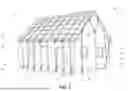
FIGS. 1, 2 and 8 each illustrate a plurality of modular panels or sections provided in pre-measured form for installation in covering relation with a particular roof structure to be protected. Looking at FIG. 1 and 2, a ridge panel 14 is shown centered over the peak or ridge of the roof 13, with one-half of the ridge panel 14 on one side of the peak and the other half on the other side. Individual panels 14 and 16 in FIG. 1, and also panel 28 inf FIG. 2, can be joined together as shown at hardware connections 17 and 18 to form a precisely sized and shaped protection blanket for the roof. Once in place on the roof to be protected, the interconnected “hurricane blanket”, or “modular panel system” can be secured to the foundation 50 so that it cannot be moved (or to a concrete slab beneath the structure, for example, if it is a shed or outdoor garage). The assembled blanket, i.e., the plurality of panels connected to one another to form a modular panel system, can be preferably connected to a plurality of tie-down straps 20 that are secured to anchors 25 bolted into the foundation 50 and tightened by ratchet straps 21, such that wind forces are transferred to the foundation 50, protecting the roof from blowing off. While the blankets illustrated in FIGS. 1 and 2 are similar and serve the same purpose, FIG. 2 differs from FIG. 1 in that it also includes a triangular-shaped “gable” panel 28 at each gable end of the house (the pointed wall under the roof), which can be useful for protecting larger roofs and structures from the storm's wind forces lifting the roof and/or the structure off of the foundation. FIG. 8 shows an even more complex hurricane blanket, and is described in more detail below.
As illustrated in FIGS. 1, 2 and 8, a plurality of nets or panels 14, 16, 28 can be strategically placed to substantially cover the entire roof of a building 12. The panels can initially be joined to one another using connection hardware 17, 18, and ultimately the blanket or modular panel system that is formed can be tightened to the structure by a plurality of tie-down straps 20, which are tensioned between the eave panels 14, 28 and a corresponding plurality of anchors 25 which are secured to the foundation 50 of the building (or to a concrete slab beneath). The plurality of tie-down straps 20 are preferably made of strong polyester or nylon webbing, and are used to secure the panels to the building by using a ratcheting mechanism 21, typically including a handle or winch, that can be cranked back and forth to tighten each strap 20. Tightening the straps in this manner can provide a “snug” fit for the interconnected panels covering the roof, without damaging the gutters or siding of the house. The strong and secure fastening of the straps 20 by the ratchets 21 can be easily adjusted and released.
The anchors 25 for the straps 20 can be screwed, bolted or otherwise permanently connected to the foundation 50 of the building 12, for example by anchor bolts, and are generally spaced at predetermined distances from one another all around the entire foundation 50, as illustrated. Once bolted to the foundation 50, each of the anchors 25 can be clipped, hooked, or otherwise joined by connection hardware (17, 18) to one of the plurality of tie-down straps 20, and each of the straps 20 can be joined to a roof panel 16 (or a gable panel 28, see FIG. 2) by similar connection hardware. As a non-limiting example, and as illustrated in FIG. 1, each roof panel 16 can be connected by hardware 17 to a ridge panel 14, which spans or covers the peak or ridge 13 of the roof. The roof panels 16, once connected to the ridge panel 14, can then be secured by the tie-down straps 20 to the foundation 50 of the building, by threading each of the straps through a corresponding one of the plurality of anchors 25. Each of the plurality of straps 20 can thereafter be tightened by their corresponding ratchet winches 21.
In a preferred embodiment of the invention, the plurality of panels includes four general types of panels, namely: ridge panels 14 for covering the peak or ridge of the roof, as illustrated in FIG. 3; roof panels 16 for connecting to the ridge panels 14 above and the tie-down straps 20 below, as illustrated in FIG. 4; “debris” or square panels 26 for covering windows and doors, as illustrated in FIG. 5; and gable or triangle panels 28 for covering the gable or other odd-shaped portion of the roof, as illustrated in FIG. 6. Indeed, there are many different areas of a roof having a different pitch and size, and to aid in fitting the various panels 14, 16, 26, 28 all together to cover a particular house, sizing straps 65 as shown in FIG. 7 can be used. Interconnecting panels such as the ridge panels 14, roof panels 16, square panels 26, triangle panels 28 and sizing straps 65 can be custom manufactured to precisely fit a particular portion of a particular roof, and the panels 14, 16, 26, 28 can then be secured to one another or otherwise interconnected as a single unit or modular panel system, which can then be secured by the tie-down straps 20 to the building's foundation 50. See also FIG. 8.
The plurality of sections or panels 14, 16, 26, 28 disclosed herein are each individually useful for specifically fitting over, covering and protecting a particular portion of a roof of a structure. The structure may be a commercial, industrial, residential, mobile, or other free standing or add-on structure. The inventive modular panel system is thus composed of individual panel units that fit together to form a whole. Each panel can also be separated or replaced independently without affecting the rest of the system, and panels already forming a system can be combined with other panels to create a larger system. This approach allows for flexibility, customization, and easier maintenance and expansion in a wide range of applications, from sheds and outdoor garages to large commercial buildings. In addition, during manufacture of the panels 14, 16, 26, 28, it is preferred that they are made without connection hardware being permanently attached. Thus, the panels are preferably made in the form of cargo nets that can connect with almost any type of connection hardware simply by attaching the connection hardware directly to the mesh webbing itself, or to small loops sewn into the webbing perimeter. This allows for decreased cost of production of the panels, as well as ease and decreased costs for shipping and storage. Therefore, although illustrated in FIGS. 3-6 having connection hardware in the form of hooks 30, 56, and D-rings 32, 34, 36, 37, 52, 54, the panels are preferably manufactured separately from the connection hardware, and the connection hardware is used as needed for connecting the panels of a particular modular panel system.
As illustrated in FIG. 3, the ridge panel 14 can be manufactured in the form of a cargo net 31 custom made to fit a portion of a particular roof. As a non-limiting example, connection hardware 17, 18 for the cargo net 31 can include hooks 30 on the long (normal) sides of the netting 35, and D-rings 32 on the short (gable-side) ends of the netting 35. The cargo netting 35 is preferably made of a 2-inch wide polyester webbing, sown into custom panel sizes with 6 inch mesh openings. For adding the hardware couplings, portions of the cargo netting can include sewn loops that can connect to almost any type of connection hardware. Polyester webbing has a higher tensile strength than polypropylene, does not stretch, and is less expensive than nylon. While the preferred netting material is polyester, the material can also be other materials that do not stretch, such as Kevlar.
It can be appreciated from looking at FIG. 3 that the ridge panel 14 is symmetrical, and therefore the ridge panel can be centered over the peak or ridge of the roof, with two (2) of the short side D-rings (i.e., one-half of the ridge panel) on one side of the peak and the other two (2) of the short side D-rings (i.e., the other half of the ridge panel) on the other side of the peak. Thus, half of the hooks 30 will be on one side of the roof, and the other half of the hooks on the other side. The hooks 30 located on the long sides of the ridge panel 14 can be joined to the D-rings 37 located on a roof panel 16 (see FIG. 4). FIGS. 1 and 2 illustrate this connection as connection hardware 17. Specifically, D-rings 37 can be seen located on the second to last row of the cargo net 35 of the roof panel 16 in FIG. 4. Also, D-rings 34 can be seen opposite to the D-rings 37 at the opposing long end of the roof panel 16, and D-rings 36 can be seen on each of the short ends of the cargo net 35 of the roof panel 16. All of these D-rings 34, 36, 37 of the roof panel 16 can be joined by a hook. Specifically, D-rings 37 can be joined to hooks 30 of a ridge panel, D-rings 34 and 36 can be joined to a hook of a tie-down strap, and D-rings 36 can also be joined to the hooks 56 of a triangle strap (see FIG. 6).
As illustrated in FIGS. 1 and 2, the roof panel 16 can be placed over the portion of the roof 13 as it angles downward toward the gutters, soffits, overhangs, or eaves. This location puts the ringed ends (37, see FIG. 4) of the roof panel 16 adjacent to the hooked ends (30, see FIG. 3) of the ridge panel 14, allowing the ridge panel 14 and the roof panel 16 to be connected to one another in covering relation to the roof. FIG. 2 illustrates these same connections between the ridge panel 14 and the roof panel 16, but also includes a triangular gable panel 28. When a gable panel is added it can be connected by attachment means such as connection hardware 18 to both the ridge panel 14 and the roof panels 16, as can be appreciated from viewing FIG. 2.
Looking at FIG. 6, hooks 56 of the triangular panel 28 can be joined to gable side D-rings 36 of the roof panel (see FIG. 4), as well as to the gable side D-rings 32 of the roof panel 14 (see FIG. 3). FIG. 5 illustrates a square panel 26, made of a cargo net 53 and having a plurality of D-rings 52 for attachment to a hook located on each side of the square net 53. The square “debris” panel 26 shown in FIG. 5 can be used to cover windows or doors to protect from flying debris, or it can be used as needed to fill in any gaps on the roof, according to its particular shape and pitch. The sizing straps 65, illustrated in FIG. 7, are typically used between panels to achieve a proper final fit. The sizing straps can be connect to the sewn loop attachment points of the cargo netting 35 via D-ring connections or other connection hardware. For example, in one embodiment, rather than D-ring connections, threaded couplers can be used at the sewn loop connection points of the cargo netting 35.
The roof panels 16 and the triangle panels 28 are preferably tightened by tensioning means such as a plurality of ratchets 21 associated with each of the plurality of tie-down straps 20 which are anchored to the foundation of the building. Additional panels, herein designated as square/debris panels 26 as shown in FIG. 4, or one or more sizing straps 65, as shown in FIG. 7, can be secured to the roof panels at the overhang of the eaves, to fill gaps as the panels are fitted onto the building, or to protect the windows and doors from flying debris (see, e.g., FIG. 8). In one embodiment the debris panels 26 may have a smaller webbing than the roof panels, so that debris is more easily blocked from reaching the windows or doors, or even the chimney top.
As noted above, although the panel-to-panel connection hardware 17, 18 is shown and described herein as D-rings and hooks, the hardware for use in connecting the inventive system is not so limited. For example, the panels can include sewn-in loops at various portions of the net for connection to threaded couplers, O-rings, buckles, grommets, N-hooks, S-hooks, carabiners, alligator clips, cobra buckles, cam buckles, webbing loops, or Velcro. For example, the cargo netting of the various panels can have sewn-in loops as connection points which can be interconnected via snap hooks and O-rings. The ratcheted tie-down straps 20 can be connected to stainless steel foundation anchors 25, 40, 60, as illustrated herein, which have been permanently bolted to the building's foundation.
To prepare a blanket system for a specific roof, measurements of the particularities of the roof can be taken by laser or other known methods, which can be entered into a computer program application that determines the optimal sizes of the various roof panels, ridge panels and square/triangle panels to be manufactured. For example, as illustrated in FIG. 1, ridge panel 14 (shown in detail in FIG. 3) can be measured and manufactured to cover the peak of the roof, and a pair of roof panels 16 (shown in detail in FIG. 4) can be used to cover the remainder of the roof including the eaves. The square panel 26 shown in FIG. 5 can be used to cover windows or doors to protect from flying debris, or it can be used as needed to fill in any gaps on the roof, according to its particular shape and pitch. The gable or triangle panel 28 shown in FIG. 6 can be used to cover the gable portion of the roof. Thus, each of these types of panels 14, 16, 26, 28 can be used to perform a specific function, with the common goal being to create a modular panel system which can aid in covering the roof like a blanket, protecting the roof and the entire building from being damaged and/or completely picked up and carried away during a windstorm.
FIG. 8 illustrates a larger, residential type building that has been covered with the various types of panels and connection hardware disclosed herein to create a modular panel system or “hurricane blanket” which can be used to cover gable roofs, hip roofs and variations thereof, such as gambrel, pavilion, mansard, tented, Dutch, and half-hip roofs. As noted, measurements of the particularities of the roof can be taken by laser or other known methods, which can be entered into a computer program application that determines the optimal sizes of the various roof panels 14, ridge panels 16, and square/triangle panels 26, 28 to be used. As illustrated, ridge panels 14 can be measured and manufactured to cover the peak of the roof, roof panels 16 to cover the eaves. The square panels 26 can be used to cover windows 15 or doors to protect from flying debris, or it can be used as needed to fill in any gaps on the roof, or even cover the chimney as illustrated in FIG. 8. Gable or triangle panels 28 are illustrated covering the gable portion of the roof. Connection hardware 17, 18, and sizing straps 65 are used to join panel to panel, and also to join the panels to tie-down straps 20, which are anchored to the foundation 50 of the building by anchors 60, and which are tightened by ratchets 21. Windows and skylight windows 15 are covered with square panels 26, and roof panels 16 can be seen covering the roof and connected to the ridge panels 14 and gable panels 28. When the various panels and connections are secured to the roof of a building in this manner, the modular panel system created can protect the roof from hurricane force winds, which otherwise would lift the roof off of the building.
Testing: Wind Loading Testing was conducted on the inventive system as substantially illustrated in FIG. 1. Testing was performed from Apr. 9, 2025 through Apr. 10, 2025. All equipment used for accuracy and data recording was calibrated with traceability to the National Institute of Standards and Technology reference standards. With the test setup confirmed, a first wind source was powered on and began exposure for the duration of 3-Hours. After 20-Minutes had elapsed, a second wind source was added to the test setup to ensure higher than 100 mph wind speeds. The second wind source was raised to the height of the roof and angled upward to achieve a more direct impact of wind onto the roof. Wind speed was generated up to 100 mph for the duration of 3-Hours per face. No visual physical damage or anomalies were observed during or after testing.
Specific foundation anchors that can be used with the present invention are shown in FIGS. 9 and 10. FIG. 9 illustrates a D-ring anchor 60 including a stainless steel plate 62 with a pair of bolt holes 63 for receiving expansion bolts, and a D-ring 64 attached in the center for connecting to the tie-down straps, for example, via hooks. FIG. 10 illustrates a plate anchor 40 which includes a stainless steel cover plate 42 with a pair of shims 44 that can fit beneath the cover plate. Expansion bolts can be inserted through holes 43 of the cover plate and holes 45 of the shims, such that the anchor 40 can be joined to the foundation. Expansion bolts can be drilled into the foundation, and can preferably have a ½″ (one-half inch) thread rod/shank made of stainless steel. As a non-limiting example of the type of concrete expansion bolts that can be used with the present invention, Red Head™ expansion bolts are a brand of heavy-duty concrete anchors, specifically wedge anchors, designed for fastening to solid concrete. They work by being hammered into a pre-drilled hole, then tightened with a nut to expand a steel clip or “wedge” at the bottom of the anchor, creating a tight and secure hold.
Advantages of the inventive modular roof blanketing system include non-stretchable cargo netting panels which are custom made to precisely fit the roof and secured to the foundation. The inventive roof protection system can be rapidly installed by home or business owners and home improvement subcontractors, and can be removed and easily stored by the home or business owner when not in use. The system thus provides custom made-to-fit panels, with end-gable panels to secure the gable end of the roof, attached by stainless hardware.
Proper fitting of the panels to securely cover the roof is a critical factor provided by the modular panel system disclosed herein. An accurate fit allows the system to function as a cohesive unit, effectively securing the roof to the structure. As noted above, the process of creating the inventive panel system preferably begins with precise roof area measurements, such as by laser, followed by the input of data into a program that generates the parameters of individual panel sections. These sections are then made to order, and can be assembled on the roof of the structure it is designed to protect, to form a matrix when fastened together. In contrast, a large, single blanket covering, as used in the prior art, presents difficult logistical challenges related to installation, removal, and storage, making these designs and processes significantly less useful and efficient. Furthermore, the inventive modular system allows for precise fit adjustments through the use of connector straps, which can facilitate efficient spacing and enable accurate tensioning to the foundation anchors. The ease of handling and storage represents a considerable advantage, particularly for seasonal installations and removals.
The panels can be manufactured by industry suppliers of such materials, and can be made of typically 2-inch wide polyester webbing, sown into custom panel sizes with 6 inch openings, with sewn-in loops or other appropriate attachment means for connecting to other panels via connection hardware. A precise measurement of all aspects, angles, and surfaces of the roof and building design will be made prior to manufacture of the panels for a particular home or building. It is also anticipated that a smaller model-version can be developed for mobile homes, sheds, or any structure sitting on a concrete slab. This application is much smaller and easier to install, often only requiring only one or two panels, and can be ratchet-strapped to the slab it is resting on.
When hurricane season has passed, the various panels of inventive roof protection system can be disassembled, folded and stored. The cost of the inventive system compared to the total loss of a dwelling is relatively inexpensive. More specifically, preventing the repair/replacement costs following the destruction of a home or business comparatively makes utilizing the inventive system inexpensive. In some circumstances it may be desirable to remove the gutter systems that are present on the building, typically until a particular storm passes and perhaps as long as the hurricane/storm season lasts. Typically a service company can be utilized to uninstall the system and reinstall the gutter systems.
Although removal and reinstallation of the gutter system may be desired by some homeowners, the present invention provides a ratcheting or cinching process in which tightening of the roof panels lengthwise along the building edge, prior to reaching the gutters, can negate the need for removal and reinstallation of gutter systems. For example, if gutters are present along the normal side of the building, the roof panels can be initially tensioned from each gable end, so that tension is created along the length of the structure, just above the point where the gutters attach to the roof. Once tensioned lengthwise in this manner, along the roof side of the gutters, the remaining portion of the roof panel will drape over the gutters and can be secured to the foundation by tie-down straps. However, the tie-down straps on the normal side of the building do not need to be tensioned as tightly as the previously tensioned gable-side straps. The normal-side tie-down straps can be ratcheted or cinched into place in a manner that is tight enough to hold down the roof edge/eaves and protect the gutter system, but not so tight as to cause damage to the gutters.
While the present invention has been illustrated by the description of embodiments and examples thereof, it is not intended to restrict or in any way limit the scope of the appended claims to such details. Additional advantages and modifications will be readily apparent to those skilled in the art. Accordingly, departures may be made from such details without departing from the scope of the invention.
Claims
1. A system for securing a roof-covered structure, wherein the system comprises:
a) a plurality of panels, wherein each of the plurality of panels is placed onto a particular portion of a roof of a structure, and wherein each of the plurality of panels is connectable to at least one other of the plurality of panels to form a blanket substantially covering the entire roof;
b) a plurality of anchors secured to the foundation of the structure;
c) a plurality of tie-down straps for tying down the plurality of panels to the plurality of anchors secured to the foundation of the structure, wherein each of the plurality of tie-down straps connects a portion of one of the plurality of panels to one of the plurality of anchors; and
d) a plurality of tensioning devices, wherein each of the plurality of tie-down straps is tightened by one of the plurality of tensioning devices to one of the plurality of anchors, wherein the system can be attached firmly to the foundation so that it cannot be moved.
2. The system of claim 1, wherein each of the plurality of panels is in the form of a cargo net precisely measured to cover a particular portion of the roof, and wherein the plurality of panels are connectable to one another by connection hardware.
3. The system of claim 2, wherein the connection hardware is selected from the group consisting of D-rings, hooks, threaded couplers, O-rings, buckles, grommets, N-hooks, S-hooks, carabiners, alligator clips, cobra buckles, cam buckles, webbing loops, Velcro, and combinations thereof.
4. The system of claim 1, wherein each of the plurality of panels is selected from the group consisting of a roof panel, a ridge panel, a gable panel, and a square panel.
5. The system of claim 1, wherein each of the plurality of panels is custom-made according to laser measurements and computer calculations to cover a specific portion of the roof, and wherein the plurality of panels form the blanket upon being connected to one another to substantially cover the entire roof.
6. The system of claim 1, wherein each of the plurality of anchors is a D-ring anchor, the D-ring anchor comprising a stainless steel plate, a pair of bolt holes for receiving expansion bolts, and a D-ring attached in the center of the steel plate for connecting to the tie-down straps.
7. The system of claim 1, wherein each of the plurality of anchors is a plate anchor, each plate anchor comprising a stainless steel cover plate, and a pair of shims for fitting beneath the cover plate, wherein the cover plate the shims each include holes for receiving expansion bolts.
8. The system of claim 1, wherein each of the plurality of anchors are secured to the concrete foundation by a plurality of expansion bolts drilled into the foundation, wherein each one of the plurality of expansion bolts includes a ½″ (one-half inch) thread rod/shank made of stainless steel.
9. The system of claim 1, wherein each of the plurality of tensioning devices is a ratchet.
10. A system for covering and securing the roof of a structure, the system comprising:
a) a plurality of panels connectable to one another by connection hardware for forming a blanket which substantially covers a roof of a structure, wherein each one of the plurality of panels is in the form of a cargo net adapted to cover a portion of the roof;
b) a plurality of anchors secured to the concrete foundation of the structure; and
c) a plurality of straps for tying down the plurality of panels to the plurality of anchors secured to the foundation, each one of the plurality of straps having a ratchet attached thereto for tightening the strap, wherein the system can be attached firmly to the foundation so that it cannot be moved.
11. The system of claim 10, wherein the connection hardware is selected from the group consisting of D-rings, hooks, threaded couplers, O-rings, buckles, grommets, N-hooks, S-hooks, carabiners, alligator clips, cobra buckles, cam buckles, webbing loops, Velcro, and combinations thereof.
12. The system of claim 10, wherein each one of the plurality of panels is selected from the group consisting of a roof panel, a ridge panel, a gable panel, and a square panel.
13. The system of claim 10, wherein each one of the plurality of panels is custom-made according to laser measurements and computer calculations to cover a specific portion of the roof, and wherein the plurality of panels form the blanket upon being connected to one another to substantially cover the entire roof.
14. The system of claim 10, wherein each of the plurality of anchors is a D-ring anchor, the D-ring anchor comprising a stainless steel plate, a pair of bolt holes for receiving expansion bolts, and a D-ring attached in the center of the steel plate for connecting to the tie-down straps.
15. The system of claim 10, wherein each of the plurality of anchors is a plate anchor, each plate anchor comprising a stainless steel cover plate, and a pair of shims for fitting beneath the cover plate, wherein the cover plate the shims each include holes for receiving expansion bolts.
16. The system of claim 10, wherein each of the plurality of anchors are secured to the concrete foundation by a plurality of expansion bolts drilled into the foundation, wherein each one of the plurality of expansion bolts includes a ½″ (one-half inch) thread rod/shank made of stainless steel.
Images & Drawings included:


Sources:
- United States Patent and Trademark Office - verify current appl. status at the USPTO↗
Recent applications in this class:
- » 20260139506 2026-05-21
Systems & Methods for Modular Hurricane-Resistant Structures - » 20250290342 2025-09-18
Fire Shelter and Method - » 20250207425 2025-06-26
REMOVEABLE ABOVE-GROUND STORM SHELTER AND METHOD OF USE - » 20240301714 2024-09-12
SHELTER APPARATUS AND METHOD THEREOF - » 20240301713 2024-09-12
Hurricane Asset Protection System for preparing real estate, vehicles, and other tangible property for natural and manmade calamities and their aftermath - » 20240247515 2024-07-25
Rafter Support Assembly and Method of Using Same - » 20240117651 2024-04-11
SECURITY VAULT - » 20230358067 2023-11-09
Security apparatus for protecting a surface - » 20230175280 2023-06-08
EMBER SCREEN - » 20230108669 2023-04-06
Structures and methods for lunar utilization