FUEL INJECTOR AND METHODS OF USE THEREOF
US20260177243A1
2026-06-25
18/999,444
2024-12-23
Smart Summary: A fuel injector has a special part called a swirl pot that creates a swirling motion for the fuel. This swirl pot has an outer body that forms a chamber where the swirling happens. Inside this chamber, there is another part called a swirler core that helps guide the fuel in a specific path. The swirler core is a separate piece from the outer body. Together, these parts work to improve how fuel is injected into an engine. 🚀 TL;DR
Abstract:
A fuel injector includes a swirl pot including an outer body defining a swirling chamber having a longitudinal axis. The fuel injector also includes a swirler core disposed within the swirling chamber substantially concentric with the longitudinal axis and together with the outer body defining at least one swirl path within the swirl chamber. The swirler core is a unitary body separate and distinct from the outer body.
Inventors:
- Rajeshriben Patel 7 🇺🇸 San Diego, CA, United States
- Bryan D. Quay 2 🇺🇸 Santee, CA, United States
- Paul ECONOMO 2 🇺🇸 Carlsbad, CA, United States
- Gregory M. BALOW 1 🇺🇸 San Diego, CA, United States
- Grace TERRIS 1 🇺🇸 San Diego, CA, United States
Assignee:
- Solar Turbines Incorporated 328 🇺🇸 San Diego, CA, United States
Applicant:
Interested in similar patents?
Get notified when new applications in this technology area are published.
Classification:
F23R3/14 » CPC main
Continuous combustion chambers using liquid or gaseous fuel characterised by the air-flow or gas-flow configuration; Air inlet arrangements for primary air inducing a vortex by using swirl vanes
F23R3/286 » CPC further
Continuous combustion chambers using liquid or gaseous fuel characterised by the fuel supply having fuel-air premixing devices
F23R3/28 IPC
Continuous combustion chambers using liquid or gaseous fuel characterised by the fuel supply
Description
GOVERNMENT LICENSE RIGHTS
This invention was made with government support under DE-FE0032106 awarded by the Department of Energy. The government has certain rights in the invention.
TECHNICAL FIELD
The present disclosure relates generally to gas turbine engines, and more particularly, to swirl pots for swirl fuel injectors that are tolerant to thermal expansion.
BACKGROUND
A combustion system for a gas turbine engine may include a fuel injector for directing fuel from a fuel supply, and an intake manifold for supplying air, to a combustion chamber of a combustor in which the fuel and air is combusted to drive rotation of one or more shafts, thereby producing mechanical energy. During operation of the gas turbine engine, different portions or areas of the fuel injector may be exposed to different temperatures. For example, a downstream portion of the fuel injector, positioned closer to combustion chamber, may be exposed to more heat from the combustion of a fuel within the combustion chamber than an upstream portion of the fuel injector, which may also be cooled by air flowing into the intake manifold. As a result, a temperature gradient may be created between the upstream portion of the fuel injector and the downstream portion of the fuel injector. Or for example, the fuel injector may be configured to direct different types of fuels to the combustion chamber, e.g., a first fuel with a relatively low concentration of hydrogen and a second fuel with a relatively high concentration of hydrogen, via a single fuel path or different fuel paths included in the fuel injector, at separate times or concurrently. The different types of fuels may have different thermal properties, such that the conveyance of the different types of fuels through the fuel injector to combustion chamber may create a thermal gradient within the fuel injector, e.g., between laterally adjacent portions of the fuel injector. A temperature gradient between different portions of the fuel injector may cause potentially harmful thermal stress between one or more components of the fuel injector.
U.S. Pat. No. 11,274,831 (the '831 patent) discloses a fuel injector nozzle for a combustion turbine engine including thermal stress-relief vanes. The fuel injector nozzle described in the '831 patent includes two or more nested, concentric, spaced annular sleeves and at least two vanes disposed between opposing sleeves.
The methods and systems of the present disclosure may solve one or more of the problems set forth above and/or other problems in the art.
SUMMARY
According to one aspect of the disclosure, a fuel injector includes a swirl pot including an outer body defining a swirling chamber having a longitudinal axis. The fuel injector also includes a swirler core disposed within the swirling chamber substantially concentric with the longitudinal axis and together with the outer body defining at least one swirl path within the swirl chamber. The swirler core is a unitary body separate and distinct from the outer body.
According to another aspect of the disclosure, a fuel injector includes a swirl pot including an outer body defining a swirling chamber and a plurality of radial vanes, each radial vane of the plurality of radial vanes including a radial pin extending toward a longitudinal axis of the swirling chamber. The fuel injector also includes a swirler core disposed within the swirling chamber and including a plurality of holes, each hole of the plurality of holes receiving a corresponding radial pin. A clearance between a hole and a corresponding radial pin allows for thermal expansion between the outer body and the swirler core.
According to yet another aspect of the disclosure, a method of manufacturing a fuel injector includes additively manufacturing an outer body of a swirl pot defining a swirling chamber having a longitudinal axis, and additively manufacturing a swirler core disposed within the swirling chamber substantially concentric with the longitudinal axis. The swirler core forms a unitary body separate and distinct from the outer body.
BRIEF DESCRIPTION OF THE DRAWINGS
The accompanying drawings, which are incorporated in and constitute a part of this specification, illustrate various exemplary embodiments and together with the description, serve to explain the principles of the disclosed embodiments.
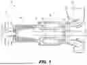
FIG. 1 depicts a schematic diagram of an exemplary embodiment of a gas turbine engine;
FIG. 2 depicts an exemplary embodiment of a fuel injector;
FIG. 3 depicts an exploded and partial cross-sectional view of an exemplary embodiment of a swirl pot;
FIG. 4 depicts a cross-sectional view of an exemplary embodiment of a swirl pot; and
FIG. 5 depicts a flowchart of an exemplary method for manufacturing a swirl pot.
DETAILED DESCRIPTION
Both the foregoing general description and the following detailed description are exemplary and explanatory only and are not restrictive of the features, as claimed. As used herein, the terms “comprises,” “comprising,” “having,” including,” or other variations thereof, are intended to cover a non-exclusive inclusion such that a process, method, article, or apparatus that comprises a list of elements does not include only those elements, but may include other elements not expressly listed or inherent to such a process, method, article, or apparatus. Moreover, in this disclosure, relative terms, such as, for example, “substantially,” are used to indicate a possible variation of ±10% in the stated value.
It should also be understood that the various components illustrated herein are not necessarily drawn to scale. In other words, the features disclosed in various embodiments may be implemented using different relative dimensions within and between components than those illustrated in the drawings.
FIG. 1 depicts a schematic diagram of an exemplary embodiment of a gas turbine engine 100. As depicted in FIG. 1, the gas turbine engine 100 may include, from an upstream end to a downstream end, an inlet manifold 110, a compressor 120, a combustor 130, a turbine 140, and an exhaust outlet 150. The gas turbine engine 100 may further include one or more shafts 102. Various components of the gas turbine engine 100, e.g., the compressor 120 and/or the turbine 140, may be coupled to and/or concentric with a longitudinal axis of the one or more shafts 102.
The inlet manifold 110 may funnel a working fluid, e.g., air, into the compressor 120. The compressor 120 may include one or more components, e.g., rotor assemblies and stator assemblies, configured to compress the working fluid. The combustor 130 may include a combustion chamber 132 configured to receive the compressed working fluid from the compressor 120 and fuel from one or more fuel injectors 134. A mixture of the compressed working fluid and the fuel may be ignited and combusted within the combustor 130. The turbine 140 may include one or more components, e.g., rotor assemblies and stator assemblies, configured to extract energy produced by the combustion of the mixture of the compressed working fluid and the fuel. The energy extracted by the turbine 140 may be transferred to an external system and/or the compressor 120 via the one or more shafts 102. Exhaust produced by the combustion of the compressed working fluid and the fuel may be expelled from the gas turbine engine 100 via the exhaust outlet 150.
FIG. 2 is a perspective view of a fuel injector 134 of the present disclosure. The fuel injector 134 may also include an injector head 204, a flange 202, and a stem 206 extending between the flange 202 and the injector head 204. The injector head 204 may include an atomizer nozzle. The fuel injector 134 may include one or more inlets (not shown) configured to receive one or more fluids. The one or more inlets may be located on the flange 202. For example, the one or more inlets of the fuel injector 134 may include a first inlet configured to receive the compressed working fluid from the compressor 120, a second inlet configured to receive a first fuel type from a first fuel source, and a third inlet configured to receive a second fuel type from a second fuel source.
The injector head 204 may include one or more swirl pots 210, through and within which fuel is mixed into the compressed working fluid and then delivered to the combustion chamber 132 of the combustor 130. The one or more fluids or fuels received by the one or more inlets may be delivered to the one or more swirl pots 210 by separate and distinct internal channels within the fuel injector 134. For example, the compressed working fluid may be delivered to a swirl pot 210 by a first internal channel, a first fuel type may be delivered to the swirl pot 210 by a second internal channel, and a second fuel type may be delivered to the swirl pot 210 by a third internal channel. Although the fuel injector 134 of FIG. 2 is shown to include seven swirl pots 210, those skilled in the art will recognize that any number of swirl pots 210 may be included and may vary depending on the application. Each swirl pot 210 included in the multi-pot swirl fuel injector 134 may include a plurality of vanes, such as radial vanes 215 and axial vanes 224 (FIG. 3), as will be discussed in more detail below. The vanes are configured to swirl the mixture of the compressed working fluid and the fuel before it is delivered to the combustion chamber 132 of the combustor 130.
FIG. 3 depicts an exploded and partial cross-sectional view of an exemplary embodiment of a swirl pot 210 of a fuel injector 134 of the present disclosure. As depicted in FIG. 3, the swirl pot 210 may include an outer body 211 and a swirler core 220. The outer body 211 is shown as a partial cross-sectional and the swirler core 222 is shown exploded from its normal disposition within the outer body 211 to illustrate details within the outer body 211. The outer body 211 may include an interior surface 212 defining a swirling chamber 230 within the swirl pot 210. Although the outer body 211 and the swirler core 220 are depicted as disjointed in the exploded view of FIG. 3, it will be understood and appreciated that the swirler core 220 is disposed completely within the swirling chamber 230 defined by interior surface 212 of the outer body 211, as depicted in cross-section in FIG. 4. The swirl pot 210, e.g., the swirling chamber 230, may include a longitudinal axis 213, and the swirler core 220 may be disposed within the swirling chamber 230 substantially concentric with the longitudinal axis 213. A radial axis 214 of the swirl pot 210, e.g., the swirling chamber 230, may refer to any axis or direction that radiates outward from the longitudinal axis 213 at a substantially orthogonal angle to the longitudinal axis 213. Together, the outer body 211 and the swirler core 220 define within the swirling chamber 230 one or more swirl paths. The compressed working fluid and/or the fuel are mixed and/or swirled along the one or more swirl paths before being delivered to the combustion chamber 132 of the combustor 130. As described in further detail below, the swirler core 220 may be a unitary body that is separate and distinct from the outer body 211 of the swirl pot 210.
The outer body 211 of the swirl pot 210 may include a plurality of radial vanes 215. Each radial vane 215 may extend from the interior surface 212 of the outer body 211 toward the longitudinal axis 213 along a radial axis 214. Each radial vane 215 may include a radial pin 216 at the end of the radial vane 215 nearest the longitudinal axis 213. The radial pin 216 may be oval shaped, as shown, or have any appropriate shape, e.g., cylindrical, and an area of a base of the radial pin 216 may be less than a radially inner surface 218 of the radial vane 215 from which the radial pin 216 extends, such that the base of the radial pin 216 and the surface of the radial vane 215 from which the radial pin 216 extends may form a lip 219 surrounding the base of the radial pin 216. The radial vanes 215 may define axial swirl paths within the swirling chamber 230.
Each radial vane 215 may additionally or alternatively include a fuel path (not shown) for delivering fuel to the swirling chamber 230. A fuel path included in a radial vane 215 may extend through a radial pin 216 included in the radial vane 215. The outer body 211 may additionally or alternatively include additional fuel paths (not shown) for delivering fuel downstream of the radial vane(s) 215. For example, the outer body 211 may include a fuel path that is substantially parallel to the interior surface 212 of the outer body 211. In an embodiment in which the outer body 211 includes a first fuel path included in a radial vane 215 and a second fuel path for delivering fuel downstream of the radial vane 215, the first fuel path may convey a first type of fuel and the second fuel path may convey a second type of fuel. For example, the first type of fuel may include a first concentration of hydrogen and the second type of fuel may include a second concentration of hydrogen. In one example, the first concentration of hydrogen may be lower than the second concentration. The hydrogen concentration in the fuel mixture can be up to 100% of the fuel mixture. While the outer body 211 of the swirl pot 210 is depicted for clarity as solid in both FIGS. 2 and 3, it will be understood and appreciated that the outer body includes the one or more fuel paths as described above, such as for delivering fuel through one or more outlet holes 218.
The swirler core 220 may include an upstream portion 221 and a downstream portion 222. The upstream portion 221 of the swirler core 220 may include a plurality of holes 223. Each hole 223 may be configured to receive a corresponding radial vane 215 of the outer body 211. For example, each hole 223 may be configured to receive the radial pin 216 of one of the corresponding radial vanes 215. The downstream portion of 222 of the swirler core 220 may include a plurality of axial vanes 224. The axial vanes 224 may extend along the exterior surface 225 of the swirler core 220 in an axial direction and from the exterior surface 225 of the swirler core 220 toward the interior surface 212 of the outer body 211 along a radial axis 214. The axial vanes 224 may define radial swirl paths within the swirling chamber 230.
FIG. 4 depicts a cross-sectional view of an exemplary embodiment of a swirl pot 210 of a fuel injector 134 of the present disclosure. As mentioned above, the swirler core 220 is disposed within the swirling chamber 230 defined by the interior surface 212 of the outer body 211. The swirler core 220 is coupled to the outer body 211 by a plurality of radial vanes 215 received within a plurality of corresponding holes 223. The holes 223 and the radial vanes 215 received within the holes 223 effectively couple the swirler core 220 to the outer body 211 of the swirl pot 210. For example, an exterior surface of a radial pin 216 received within a hole 223 may prevent substantial movement of the swirler core 220 within the swirling chamber 230 along an axial direction, e.g., a direction substantially parallel to the longitudinal axis 213. Or for example, a lip 219 surrounding a base of a radial pin 216 received within a hole 223 may prevent substantial movement of the swirler core 220 within the swirling chamber 230 along a radial direction. Similarly, the axial vanes 224 may prevent substantial movement of the swirler core 220 within the swirling chamber 230 along a radial direction.
Between any radial vane 215 received within any corresponding hole 223, there may be an axial clearance or gap 241 and/or a radial clearance or gap 242. For example, there may be an axial clearance 241 between an interior surface of a hole 223 and an exterior surface of a radial pin 216 received within the hole 223 and/or a radial clearance 242 between an exterior surface 225 of the swirler core 220 surrounding a hole 223 and a lip surrounding the base of a radial pin 216 received in the hole 223. An axial clearance 241 between a radial vane 215 and a corresponding hole 223 may be less than 0.01 inches. A radial clearance 242 between the exterior surface 225 of the swirler core 220 and a radial vane 215 may also be less than 0.01 inches. Similarly, between any axial vane 224 and the interior surface 212 of the outer body 211, there may be a radial clearance 243. A radial clearance 243 between the interior surface 212 of the outer body 211 and an axial vane 224 may also be less than 0.01 inches.
As described in further detail below, various components of the fuel injector 134 may be formed through one or more additive manufacturing processes. For example, an outer body 211 of a swirl pot 210 and a swirler core 220 disposed within a swirling chamber 230 defined by an interior surface 212 of the outer body 211 may be formed during or through a single, continuous additive manufacturing process. Or for example, the fuel injector 134 may be entirely formed during or through a single, continuous additive manufacturing process.
INDUSTRIAL APPLICABILITY
The systems, apparatuses, and methods disclosed herein may find application in any system that may experience potentially harmful thermal stress between components. In particular, the systems, apparatuses, and methods disclosed herein may be advantageously used in fuel injectors for gas turbine engines.
Disclosed herein is a fuel injector 134 including a plurality of swirl pots 210. Each swirl pot 210 includes a swirler core 220 disposed within a swirling chamber 230 defined by an outer body 211 of the swirl pot 210. The swirler core 220 is a unitary body that is separate and distinct from the outer body 211. While the swirler core 220 is substantially fixed in place within the swirling chamber 230 by one or more features of the outer body 211 and the swirler core 220, clearances between the one or more features of the outer body 211 and the swirler core 220 allow for thermal expansion between the outer body 211 and the swirler core 220 without subjecting components of the swirl pot to potentially harmful thermal stress.
For example, referring to FIGS. 1 and 4, during the operation of a gas turbine engine 100 including a fuel injector 134, a downstream portion of a swirl pot 210 included in the fuel injector 134 may be positioned closer to the combustion chamber of 132 of a combustor 130 included in the gas turbine engine 100 than an upstream portion of the swirl pot 210. Thus, the downstream portion of the swirl pot 210 may be exposed to more heat produced by the combustion of a fuel within the combustion chamber 132 than the upstream portion of the swirl pot. As a result, a temperature gradient may be created between the upstream portion of the swirl pot 210 and the downstream portion of the swirl pot 210, e.g., along the longitudinal axis 213 of the swirl pot 210. Or for example, during the operation of the gas turbine engine 100, a first fuel with a relatively low concentration of hydrogen may be conveyed through the swirling chamber 230 of the swirl pot 210, and a second fuel with a relatively high concentration of hydrogen may be conveyed through a fuel path within the outer body 211 of the swirl pot 210, as described above. Because hydrogen is an effective cooling agent, the first fuel conveyed through the swirling chamber 230 may have a higher temperature than the second fuel conveyed through the fuel path within the outer body 211 of the swirl pot 210. As a result, a temperature gradient may be created between the swirling chamber 230 and the outer body 211 of the swirl pot 210, e.g., along a radial axis 214 of the swirl pot 210.
A temperature gradient created within the swirl pot 210 may cause one or more components of the swirl pot 210, e.g., a radial vane 215 of the outer body 211 or an axial vane of the swirler core 220, to thermally expand. A clearance or gap between the outer body 211 and the swirler core 220 may allow for the one or more components of the swirl pot 210 to thermally expand without applying stress on any other component of the swirl pot 210. For example, an axial clearance 241 between an interior surface of a hole 223 of the swirler core 220 and an exterior surface of a radial pin 216 of the outer body 211 may allow the swirler core 220 to thermally expand in an axial direction without applying stress to the radial pin 216, or may allow the radial pin 216 to thermally expand in an axial direction without applying stress to the swirler core 220. Or for example, a radial clearance 242 between the exterior surface of the swirler core 220 and the exterior surface of the radial pin 216 may allow the swirler core 220 to thermally expand in a radial direction without applying stress to the radial pin 216, or may allow the radial pin 216 to thermally expand in a radial direction without applying stress to the swirler core 220. Similarly, a radial clearance 243 between an interior surface 212 of the outer body 211 and an axial vane 224 of the swirler core 220 may allow the outer body 211 to thermally expand in a radial direction without applying stress to the swirler core 220, or may allow the axial vane 224 to thermally expand without applying stress to the outer body 211.
If, for example, a radial vane 215 of the outer body 211 were fixed to the exterior surface of the swirler core 220, such that the outer body 211 and the swirler core 220 formed a unitary body, thermal expansion of the radial vane 215 or the swirler core 220 may apply stress to the connection between the radial vane 215 and the swirler core 220, which may cause damage to or failure of the swirl pot 210, the fuel injector 134, or the gas turbine engine 100. Similarly, if axial vanes 224 of the swirler core 220 were fixed to the interior surface 212 of the outer body 211, such that the outer body 211 and the swirler core 220 formed a unitary body, thermal expansion of the axial vane 224 or the outer body 211 may cause damage to or failure of the swirl pot 210, the fuel injector 134, or the gas turbine engine 100. However, because the swirler core 220 is a unitary body that is separate and distinct from the outer body 211 due to axial clearances 241 and radial clearances 242, 243 between the swirler core 220 and the outer body 211 that allow for thermal expansion, such damage or failure may be avoided. In this way, the swirl pot 210 may be considered thermal expansion-tolerant.
While an axial clearance 241 or a radial clearance 242, 243 between two or more components of the swirl pot 210 may allow for one or more components of the swirl pot 210 to thermally expand without applying stress on any other component of the swirl pot 210, an axial clearance 241 or a radial clearance 242, 243 between two or more components of the swirl pot 210 may be small enough that the swirler core 220 is held substantially in place within the swirling chamber 230 defined by the interior surface 212 of the outer body 211. For example, while axial clearances 241 between a plurality of radial pins 216 of the outer body 211 received within a corresponding plurality of holes 223 of the swirler core 220 may allow for a radial pin 216 to expand without applying stress to the swirler core 220, and vice versa, the radial pins 216 received within the holes 223 may prevent substantial movement of the swirler core 220 within the swirling chamber 230 along an axial direction of the swirl pot 210. Similarly, while radial clearances 243 between a plurality of axial vanes 224 of the swirler core 220 and the interior surface 212 of the outer body 211 may allow for an axial vane 224 to thermally expand without applying stress to the interior surface 212, and vice versa, the axial vanes 224 may prevent substantial movement of the swirler core 220 within the swirling chamber 230 along a radial direction of the swirl pot 210.
As mentioned above, various components of the fuel injector 134 may be formed through one or more additive manufacturing processes. For example, the outer body 211 and the swirler core 220, which may be a unitary body that is separate and distinct from the outer body 211 due to axial clearances 241 and radial clearances 242, 243 between the swirler core 220 and the outer body 211, may be jointly formed during or through a single, continuous additive manufacturing process. An additive manufacturing process may include, for example, laser deposition or laser sintering. An additive manufacturing process may include post-processing steps including, but not limited to: de-powdering, washing, drying, deburring, cleaning, heat treating, and inspection. Additionally or alternatively, various components of the fuel injector 134 may be formed through one or more conventional manufacturing techniques, such as milling, machining, brazing, welding, etc.
FIG. 5 depicts a flowchart of a method 300 for manufacturing a swirl pot 210 of a fuel injector 134. Although steps of the method 300 are shown and described in a particular order, it will be understood and appreciated that the steps of the method 300 may be performed in any appropriate order, or simultaneously.
As depicted in FIG. 5, the method 300 may include a step 302 including additively manufacturing an outer body 211 of the swirl pot 210 defining a swirling chamber 230 having a longitudinal axis 213. The method 300 may further include a step 304 including additively manufacturing a swirler core 220 disposed within the swirling chamber 230 and substantially concentric with the longitudinal axis 304. As described above, the swirler core 220 may be a unitary body that is separate and distinct from the outer body 211 due to one or more clearances or gaps formed between the swirler core 220 and the outer body 211 through the steps of the method 300. As mentioned above, in some instances, the outer body 211 and the swirler core 220 may be formed during or through a single, continuous additive manufacturing process, e.g., the steps 302 and 304 of the method 300 may be performed concurrently. For example, in some instances, during or through an additive manufacturing process, the outer body 211 and the swirler core 220 may be formed in a successive plurality of layers perpendicular to the longitudinal axis 213 such that an individual layer of the plurality of layers may include one or more portions of the outer body 211 and one or more portions of the swirler core 220, and the additive manufacturing process continues uninterrupted until both the outer body 211 and the swirler core 220 are fully formed. The method 300 of additively manufacturing can further include post-processing steps such as grinding, heat treatments, cleaning, or other operations or combinations of operations.
By forming a swirl pot 210 of a fuel injector 134 to include clearances, e.g., axial clearances 241 and radial clearances 242, 243, between an outer body 211 of the swirl pot 210 and a swirler core 220 disposed within a swirling chamber 230 defined by an interior surface 212 of the outer body 211, damage to and/or failure of the swirl pot 210 may be reduced or avoided if/when one or more components of the swirl pot 210 thermally expand. In addition to the clearances formed within the swirl pot 210, forming the swirler core 220 to include 1) a plurality of holes 223 that receive a corresponding plurality of radial pins 216 extending along a radial axis 214 of the swirl pot 210 from an interior surface 212 the outer body 211 toward a longitudinal axis 213 of the swirl pot 210 and 2) axial vanes 224 extending along a radial axis 214 of the swirl pot 210 from an exterior surface of the swirler core 220 toward the interior surface 212 of the outer body 211, the swirler core 220 may be held substantially in place within the swirling chamber 230 defined by the interior surface 212 of the outer body 211.
It will be apparent to those skilled in the art that various modifications and variations can be made to the disclosed methods and systems without departing from the scope of the disclosure. Other embodiments of the methods and systems will be apparent to those skilled in the art from consideration of the specification and practice of the apparatus and system disclosed herein. It is intended that the specification and examples be considered as exemplary only, with a true scope of the disclosure being indicated by the following claims and their equivalents.
Claims
1. A fuel injector, comprising:
a swirl pot including an outer body defining a swirling chamber having a longitudinal axis; and
a swirler core disposed within the swirling chamber substantially concentric with the longitudinal axis and together with the outer body defining at least one swirl path within the swirl chamber, wherein the swirler core is a unitary body separate and distinct from the outer body such that movement of the swirler core within the swirl pot in an axial direction and in a radial direction with respect to the longitudinal axis is permitted, but limited, by the swirl pot to allow for thermal expansion of the swirler core and the swirl pot.
2. The fuel injector of claim 1, wherein the swirler core is coupled to the outer body of the swirl pot by a plurality of radial vanes extending radially from an interior surface of the outer body toward the longitudinal axis of the swirling chamber.
3. The fuel injector of claim 2, wherein the swirler core includes a plurality of holes, and wherein each radial vane of the plurality of radial vanes is received within a corresponding hole of the plurality of holes.
4. The fuel injector of claim 3, wherein a clearance between each radial vane and the corresponding hole allows for thermal expansion between the outer body and the swirler core.
5. The fuel injector of claim 4, wherein the clearance is an axial clearance.
6. (canceled)
7. The fuel injector of claim 4, wherein the clearance is a radial clearance.
8. The fuel injector of claim 3, wherein an axial clearance between each radial vane and the corresponding hole allows for thermal expansion between the outer body and the swirler core in axial direction of the swirling chamber, and wherein a radial clearance between each radial vane and the corresponding hole allows for thermal expansion between the outer body and the swirler core in a radial direction of the swirling chamber.
9. The fuel injector of claim 1, wherein the swirler core includes a plurality of axial vanes extending from an exterior surface of the swirler core toward an interior surface of the outer body, and wherein a clearance between at least one axial vane of the plurality of axial vanes and the interior surface of the outer body allows for thermal expansion between the outer body and the swirler core.
10. The fuel injector of claim 9, wherein the clearance is a radial clearance.
11. A fuel injector, comprising:
a swirl pot including an outer body defining a swirling chamber and a plurality of radial vanes, each radial vane of the plurality of radial vanes including: 1) a radial pin extending toward a longitudinal axis of the swirling chamber and 2) a lip formed by a base of the radial pin and a radially inner surface of the radial vane; and
a swirler core disposed within the swirling chamber and including a plurality of holes on an outer surface of the swirler core, each hole of the plurality of holes receiving a corresponding radial pin,
wherein an axial clearance between a first radial pin of a first radial vane of the plurality of radial vanes and a first hole of the plurality of holes on the outer surface of the swirler core allows for thermal expansion of the swirler core or the swirl pot in an axial direction,
wherein a radial clearance between a first lip of the first radial vane and the outer surface of the swirler core allows for thermal expansion between the outer body and the swirler core in a radial direction, and
wherein both the axial clearance and the radial clearance are less than 0.01 inches.
12. (canceled)
13. (canceled)
14. (canceled)
15. (canceled)
16. A method of manufacturing a fuel injector, comprising:
additively manufacturing an outer body of a swirl pot defining a swirling chamber having a longitudinal axis; and
additively manufacturing a swirler core disposed within the swirling chamber substantially concentric with the longitudinal axis,
wherein the swirler core forms a unitary body separate and distinct from the outer body such that movement of the swirler core within the swirl pot in an axial and in a radial direction with respect to the longitudinal axis is permitted, but limited, by the swirl pot to allow for thermal expansion of the swirler core and the swirl pot.
17. The method of claim 16, wherein the outer body includes a plurality of radial vanes extending radially from an interior surface of the outer body toward the longitudinal axis of the swirling chamber, wherein the swirler core includes a plurality of holes, and wherein each radial vane of the plurality of radial vanes is received within a corresponding hole of the plurality of holes.
18. The method of claim 17, wherein the outer body and the swirler core are formed during a single, continuous additive manufacturing process.
19. The method of claim 18, wherein an axial clearance between a radial vane and a corresponding hole allows for thermal expansion between the outer body and swirler core in an axial direction of the swirling chamber, and wherein a radial clearance between the radial vane and the corresponding hole allows for thermal expansion between the outer body and the swirler core in a radial direction of the swirling chamber.
20. The method of claim 16, wherein the swirler core includes a plurality of axial vanes extending from an exterior surface of the swirler core toward an interior surface of the outer body, and wherein a radial clearance between at least one axial vane of the plurality of axial vanes and an interior surface of the outer body allows for thermal expansion between the outer body and the swirler core.
21. The fuel injector of claim 1, wherein the movement of the swirler core within the swirl pot in the axial and the radial direction is permitted, but limited, by axial and radial clearances, respectively, between the swirler core and the swirl pot, and wherein the axial and radial clearances are each less than 0.01 inches.
22. The fuel injector of claim 11, wherein a cross-section of the first radial pin perpendicular to the radial direction is oval shaped.
23. The fuel injector of claim 11, wherein a cross-section of each radial pin perpendicular to the radial direction is oval shaped.
24. The fuel injector of claim 11, wherein the plurality of radial vanes defines a plurality of axial swirl paths within the swirling chamber.
25. The fuel injector of claim 11, wherein each radial vane of the plurality of radial vanes includes a fuel path for delivering fuel to the swirling chamber.
Images & Drawings included:


Sources:
- United States Patent and Trademark Office - verify current appl. status at the USPTO↗
Recent applications in this class:
- » 20260168671 2026-06-18
FUEL AND AIR INJECTION APPARATUS - » 20260168670 2026-06-18
FUEL INJECTOR ARCHITECTURES FOR TURBINE ENGINES WITH MULTI-STAGE GEOMETRY, STAGED FUEL INJECTION, AND HYBRID SWIRL CONTROL - » 20260153237 2026-06-04
FUEL NOZZLE AND GAS TURBINE ENGINE - » 20260153236 2026-06-04
COMBUSTOR FOR A GAS TURBINE - » 20260126175 2026-05-07
LOW-EMISSION COMBUSTOR HEAD STRUCTURE WITH V-SHAPED TRAILING EDGE VANE - » 20260126174 2026-05-07
NOZZLE FOR FEEDING AIR AND LIQUID FUEL INTO A COMBUSTION CHAMBER, AND ENGINE - » 20260117977 2026-04-30
HYDROGEN NOZZLE WITH MULTIPLE FLOW CIRCUITS AND FLOW DIRECTING SWIRLER - » 20260071755 2026-03-12
FUEL NOZZLE AND SWIRLER - » 20260049718 2026-02-19
TURBINE ENGINE WITH FUEL NOZZLE - » 20250321004 2025-10-16
NOZZLE BODY FOR FUEL INJECTOR
Recent applications for this Assignee:
- » 20260168410 2026-06-18
RESONATOR FOR TURBINE ENGINES - » 20260126015 2026-05-07
INTERCHANGING DRIVE TRAIN SYSTEM - » 20260098476 2026-04-09
TURBINE BLADE WITH COOLING FEATURES - » 20260092820 2026-04-02
METHOD AND SYSTEM FOR DETECTING ERRORS IN TEMPERATURE READINGS IN GAS TURBINE ENGINES - » 20260071694 2026-03-12
SYSTEM AND METHOD FOR DETERMINING PRESENCE OF CONTAMINANTS IN A FUEL VALVE - » 20260036093 2026-02-05
SYSTEM AND METHOD FOR DELIVERING FUEL TO A GAS TURBINE ENGINE - » 20260036053 2026-02-05
VANE ASSEMBLY FOR A GAS TURBINE ENGINE SYSTEM - » 20260022639 2026-01-22
TURBINE BLADE COOLING FEATURES - » 20250361839 2025-11-27
FUEL INJECTOR AND METHODS OF USE - » 20250290746 2025-09-18
ALIGNMENT TOOL FOR GAS TURBINE SYSTEMS