SLING MOUNT
US20260177348A1
2026-06-25
19/419,845
2025-12-15
Smart Summary: A sling mount is designed to hold a loop of material from a sling securely. It has a basket with a gap that allows access to its inside and a nose that helps keep the loop in place. A wire gate stretches across this gap, with one end connected to a hinge base. This hinge base helps the wire gate stay closed by pushing it against the basket's nose. Finally, the base of the sling mount can be attached to other equipment or accessories. 🚀 TL;DR
Abstract:
A sling mount is configured to releasably capture a loop of material at one end of a sling. The sling mount comprises a basket, a wire gate, a hinge base, and a base portion. The basket defines an interior cavity and a gap that provides access to the interior cavity and includes a nose adjacent the gap. The wire gate is configured to extend across the gap and has a proximal end and a distal end. The hinge base is configured to receive the proximal end of the wire gate. The proximal end of the wire gate cooperates with the hinge base to generate a biasing force that urges the wire gate toward a closed position in which the wire gate spans the gap of the basket and the distal end rests against the nose. The base portion is configured for attachment to an accessory mounting interface.
Inventors:
- Jonah Tyree 3 🇺🇸 Ooltewah, TN, United States
- Garrett Miller 2 🇺🇸 McDonald, TN, United States
Applicant:
Interested in similar patents?
Get notified when new applications in this technology area are published.
Description
CROSS-REFERENCE TO RELATED APPLICATION(S)
This application claims the benefit of U.S. Provisional Application Ser. No. 63/735,957, filed on Dec. 19, 2024, the entirety of which is incorporated herein by reference.
TECHNICAL FIELD
This disclosure relates to implementations of a sling mount configured to releasably secure an end of a firearm sling.
BACKGROUND
Slings are frequently used to support the weight of a firearm, to stabilize the firearm while aiming and firing, and to facilitate carrying the firearm over long distances. A variety of sling mounts exist, including fixed loops and quick-detach (QD) sockets. However, fixed loops are often used in conjunction with metal hooks, and QD sockets are often used in conjunction with metal sling swivels. Such metal-on-metal interfaces can generate noise during movement of the firearm and sling, which may be undesirable in tactical or other situations where noise discipline is important.
SUMMARY
It is to be understood that this summary is not an extensive overview of the disclosure. This summary is exemplary and not restrictive, and it is intended neither to identify key or critical elements of the disclosure nor delineate the scope thereof. The sole purpose of this summary is to explain and exemplify certain concepts of the disclosure as an introduction to the following complete and detailed description.
Disclosed are implementations of a sling mount configured to releasably capture a loop of material, such as paracord or nylon-coated steel, at one end of a sling.
In one example implementation, a sling mount comprises a basket, a wire gate, a hinge base, and a base portion. The basket defines an interior cavity and a gap that provides access to the interior cavity and includes a nose adjacent the gap. The wire gate is configured to extend across the gap and has a proximal end and a distal end. The hinge base is configured to receive the proximal end of the wire gate. The proximal end of the wire gate cooperates with the hinge base to generate a biasing force that urges the wire gate toward a closed position in which the wire gate spans the gap of the basket and the distal end rests against the nose. The base portion is configured for attachment to an accessory mounting interface.
In another example implementation, a sling mount comprises a curved basket, a hinge base, a wire gate, and a base portion. The curved basket defines an interior cavity and a gap that provides access to the interior cavity and includes a nose that defines one end of the gap. The wire gate has a proximal end affixed to the hinge base and a distal end. The proximal end of the wire gate cooperates with the hinge base to generate a biasing force that urges the wire gate toward a closed position in which the wire gate spans the gap of the curved basket and the distal end rests against the nose. The base portion is configured for attachment to an accessory mounting interface.
In yet another example implementation, a sling mount comprises a basket, a hinge base, a wire gate, and a base portion. The basket comprises a first end and a second end that define a gap therebetween, and an interior cavity configured to receive a loop of material. The wire gate has a proximal end that forms a hinge with the hinge base and a distal end that selectively closes the gap of the basket. The base portion is configured for attachment to a rail interface system.
Any aspect of any implementation, in combination with any one or more aspects of any other implementation(s).
Any one or more of the features disclosed herein.
Any one or more of the features as substantially disclosed herein.
Any one or more of the features as substantially disclosed herein, in combination with any one or more other features as substantially disclosed herein.
Any one of the aspects, features, or implementations, in combination with any one or more other aspects, features, or implementations.
Use of any one or more of the aspects or features disclosed herein.
It should be appreciated that any feature described herein can be claimed in combination with any other feature(s) described herein, regardless of whether the features originate from the same described implementation.
The details of one or more aspects of the disclosure are set forth in the accompanying drawings and the description below. Other features, objects, and advantages of the techniques described in this disclosure will be apparent from the description and drawings, and from the claims.
Numerous additional features and advantages of the present disclosure will become apparent to those skilled in the art upon consideration of the implementation descriptions provided below.
Additional features and advantages are described herein and will be apparent from the following description and figures.
BRIEF DESCRIPTION OF THE DRAWINGS
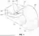
FIG. 1 is a perspective view of a sling mount in accordance with the principles of the present disclosure.
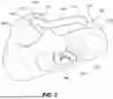
FIG. 2 is another perspective view of the sling mount shown in FIG. 1.
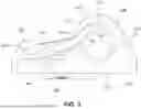
FIG. 3 is a right side elevational view of the sling mount shown in FIG. 1.
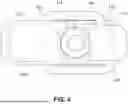
FIG. 4 is a top plan view of the sling mount shown in FIG. 1.
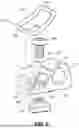
FIG. 5 is an exploded perspective view of the sling mount shown in FIG. 1.
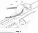
FIG. 6 is a view illustrating the sling mount shown in FIG. 1 attached to an accessory mounting interface.
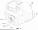
FIG. 7 is a perspective view of another sling mount in accordance with the principles of the present disclosure.
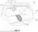
FIG. 8 is another perspective view of the sling mount shown in FIG. 7.
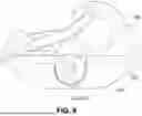
FIG. 9 is a right side elevational view of the sling mount shown in FIG. 7.
FIG. 10 is a top plan view of the sling mount shown in FIG. 7.
FIG. 11 is an exploded perspective view of the sling mount shown in FIG. 7.
FIG. 12 is a view illustrating the sling mount shown in FIG. 7 attached to a rail interface system.
Like reference numerals refer to corresponding parts throughout the several views of the drawings.
DETAILED DESCRIPTION
FIGS. 1-6 illustrate a sling mount 100 in accordance with the principles of the present disclosure. The sling mount 100 is configured to releasably secure one end of a firearm sling and attach to an M-LOK-compatible accessory mounting interface. More specifically, the sling mount 100 is configured to releasably capture a loop of material 104, such as paracord or nylon-coated steel, at one end of the sling. Using a non-metal loop 104 reduces or eliminates noise caused by metal-on-metal contact that is common with metal quick-detach (QD) swivels.
The sling mount 100 includes a curved basket 112, a wire gate 114, a hinge base 116 with two mounting holes 118, and a base 120 configured for attachment to an accessory mounting interface. A gap 122 is defined between two ends 124, 126 of the curved basket 112. The wire gate 114 is sized and dimensioned to span the gap 122, with its proximal end 128 affixed to the hinge base 116 to form a hinge and its distal end 130 resting against the nose 124 of the curved basket 112. The nose 124 is the end of the curved basket 112 at which the distal end 130 of the wire gate 114 closes. Together, the curved basket 112 and the wire gate 114 form a closed loop around an interior cavity 132.
An inward force applied to the wire gate 114 pivots the wire gate 114 around the hinge, creating a gate opening between the distal end 130 of the wire gate 114 and the nose 124 of the curved basket 112. While the wire gate 114 is open, a loop 104 can be fed through the gap 122 in the curved basket 112. When the inward force is removed, the proximal end 128 applies pressure to return the wire gate 114 to its rest position, closing the gap 122 and securing the loop 104 within the interior cavity 132. At rest, the proximal end 128 applies a biasing force to the wire gate 114 that urges the distal end 130 into a notch 134 in the nose 124 of the curved basket 112, thereby preventing the wire gate 114 from swinging open in response to outward forces applied from within the interior cavity 132, such as when the loop 104 is pulled against an interior side of the wire gate 114.
The curved basket 112 is shaped to minimize friction and wear, providing a smooth surface for the loop of material 104, attached to the sling, to rest on during use. While a curved basket 112 is depicted, the basket could incorporate an alternative interior shape that similarly minimizes friction and wear.
Together, the hinge base 116 and the proximal end 128 of the wire gate 114 form the hinge. The proximal end 128 of the wire gate 114 includes two ends 136, 138 secured within separate, offset mounting holes 118 in the hinge base 116. This configuration of the proximal end 128 and the hinge base 116 generates the biasing force that causes the wire gate 114 to return to its rest position.
The base 120 of the sling mount 100 is configured for attachment to an M-LOK slot but could alternatively be configured for attachment to a KeyMod slot or another type of accessory mounting interface. The sling mount 100 is attached to an M-LOK slot using a threaded fastener 140 and a T-nut 142, which are well known to those of ordinary skill in the art. The threaded fastener 140 extends through an opening 144 in the body 110 of the sling mount 100, which is positioned between the hinge base 116 and the curved basket 112.
The body 110 of the sling mount 100 may be formed from a polymer material, such as nylon 12; from a metal alloy, such as 7075-T6 aluminum; or from another suitable material or combination of materials. The wire gate 114 may be formed from a metal alloy, such as stainless steel, but it could also be formed from another suitable material or combination of materials.
FIGS. 7-12 illustrate another sling mount 200 in accordance with the principles of the present disclosure. The sling mount 200 is similar to the sling mount 100 disclosed above. However, the base 220 of the sling mount 200 is configured for attachment to a rail interface system, such as a MIL-STD-1913 rail.
The base 220 of the sling mount 200 includes rail clamps 250, 252 used in conjunction with a threaded fastener 254 to securely clamp the sling mount 200 to a rail interface system. The threaded fastener 254 extends laterally and transversely through lateral openings in the left and right rail clamps 250, 252 of the base 220. The head 255 of the fastener 254 is positioned in a counterbore 256 in one rail clamp 250, and the threaded end extends through the opposite rail clamp 252 to removably couple with a threaded hex nut 258 positioned in a recess. The positions of the fastener head 255 and hex nut 258 may alternatively be reversed, placing them on opposite sides of the base 220. The sling mount 200 is secured to the rail interface system by tightening the threaded fastener 254, which compresses the rail clamps 250, 252 laterally and draws the rail clamps 250, 252 together, thereby securely clamping the sling mount 200 to the rail interface system.
The foregoing description of the invention is intended to be illustrative; it is not intended to be exhaustive or to limit the claims to the precise forms disclosed. Those skilled in the relevant art can appreciate that many modifications and variations are possible in light of the foregoing description and associated drawings.
Reference throughout this specification to an “embodiment,” “implementation,” or words of similar import indicates that a particular described feature, structure, or characteristic is included in at least one embodiment of the present disclosure. Thus, the phrase “in some implementations,” or a phrase of similar import, as used throughout this specification, does not necessarily refer to the same embodiment.
The described features, structures, or characteristics may be combined in any suitable manner in one or more embodiments. In the above description, numerous specific details are provided for a thorough understanding of embodiments of the present disclosure. One skilled in the relevant art will recognize, however, that embodiments of the present disclosure can be practiced without one or more of the specific details, or with other methods, components, materials, etc. In other instances, well-known structures, materials, or operations may not be shown or described in detail.
Claims
1. A sling mount comprising:
a basket defining an interior cavity and a gap that provides access to the interior cavity, the basket including a nose adjacent the gap;
a wire gate configured to extend across the gap, the wire gate having a proximal end and a distal end;
a hinge base configured to receive the proximal end of the wire gate, the proximal end cooperating with the hinge base to generate a biasing force that urges the wire gate toward a closed position in which the wire gate spans the gap of the basket and the distal end rests against the nose; and
a base portion configured for attachment to an accessory mounting interface.
2. The sling mount of claim 1, wherein the proximal end is seated in two offset mounting holes of the hinge base to generate the biasing force that urges the wire gate toward the closed position.
3. The sling mount of claim 2, wherein application of an inward force to the wire gate pivots the distal end of the wire gate away from the nose of the basket to create a gate opening for receiving a loop of material, and removal of the inward force allows the biasing force to return the wire gate to the closed position.
4. The sling mount of claim 1, wherein the nose of the basket includes a notch.
5. The sling mount of claim 4, wherein, in the closed position, the distal end of the wire gate rests in the notch of the nose.
6. A sling mount comprising:
a curved basket defining an interior cavity and a gap that provides access to the interior cavity, the curved basket including a nose that defines one end of the gap;
a hinge base;
a wire gate having a proximal end affixed to the hinge base and a distal end, the proximal end cooperating with the hinge base to generate a biasing force that urges the wire gate toward a closed position in which the wire gate spans the gap of the curved basket and the distal end rests against the nose; and
a base portion configured for attachment to an accessory mounting interface.
7. The sling mount of claim 6, wherein the nose of the curved basket includes a notch.
8. The sling mount of claim 7, wherein, in the closed position, the distal end of the wire gate rests in the notch of the nose.
9. The sling mount of claim 6, wherein the hinge base includes two mounting holes, and the proximal end of the wire gate has two ends that are respectively received in the two mounting holes of the hinge base.
10. The sling mount of claim 9, wherein the two mounting holes of the hinge base are offset from each other.
11. The sling mount of claim 6, wherein application of an inward force to the wire gate pivots the distal end of the wire gate away from the nose of the curved basket to create a gate opening for receiving a loop of material, and removal of the inward force allows the biasing force to return the wire gate to the closed position.
12. A sling mount comprising:
a basket comprising a first end and a second end that define a gap therebetween, and an interior cavity configured to receive a loop of material;
a hinge base;
a wire gate having a proximal end that forms a hinge with the hinge base and a distal end that selectively closes the gap of the basket; and
a base portion configured for attachment to a rail interface system.
13. The sling mount of claim 12, wherein the base portion includes a first rail clamp, a second rail clamp, and a threaded fastener.
14. The sling mount of claim 13, wherein tightening the threaded fastener draws the first rail clamp and the second rail clamp together to secure the sling mount to the rail interface system.
15. The sling mount of claim 12, wherein the first end of the basket includes a notch.
16. The sling mount of claim 15, wherein, in a closed position, the distal end of the wire gate rests in the notch of the first end.
17. The sling mount of claim 12, wherein the hinge base includes two mounting holes, and the proximal end of the wire gate has two ends that are respectively received in the two mounting holes of the hinge base.
18. The sling mount of claim 17, wherein the two mounting holes of the hinge base are offset from each other.
19. The sling mount of claim 12, wherein application of an inward force to the wire gate pivots the distal end of the wire gate away from the first end of the basket to create a gate opening for receiving a loop of material, and removal of the inward force allows the biasing force to return the wire gate to a closed position.
Images & Drawings included:


Sources:
- United States Patent and Trademark Office - verify current appl. status at the USPTO↗
Similar patent applications:
- » 20180356185
Apparatus for providing a sling mount point for a firearm - » 13741987
Revolving rear sling mount for a firearm - » 20060048431
RAIL MOUNTED SLING FITTING - » 17902958
Sling mount for lever action firearm - » 20060254113
Sling mounts for firearms - » 20090288325
Sling mounts for firearms - » 20120011758
Integrated sling mount and recoil lug - » 20130232842
FNH SLP Sling Mount Adapter - » 20150292833
Rear sling mount - » 20190107364
SWINGER STOCK AND SWINGER SLING MOUNT, SWINGER STOCK, AND INSERT FOR THE SOPMOD STOCK
Recent applications in this class:
- » 20260160518 2026-06-11
FIREARM SLING CONNECTOR WITH A MOUNT ASSEMBLY AND ONE OR MORE LOOPS - » 20260085909 2026-03-26
FIREARM SLING CONNECTOR WITH A SWIVEL ASSEMBLY - » 20250237469 2025-07-24
FIREARM SLING MOUNT STUD - » 20250003714 2025-01-02
Portable Object Support System - » 20240210142 2024-06-27
SLING SLIDER - » 20240151492 2024-05-09
QUICK DISCONNECT SLING MOUNT FOR A FIREARM - » 20230408222 2023-12-21
GATE-KEEPER RIFLE HOLDER - » 20230280126 2023-09-07
SHOULDER-STRAP-BASED CARGO CARRYING HOOK - » 20220390202 2022-12-08
Firearm support system - » 20220333895 2022-10-20
Sling slider