HEATING COMPONENT AND AEROSOL GENERATING DEVICE
US20260182653A1
2026-07-02
19/552,286
2026-02-27
Smart Summary: A new device helps create aerosols without burning materials. It has a special heating part that warms up a specific section of the material used to generate the aerosol. This heating part wraps around the material but is shorter than the material itself. The design ensures that only the right amount of heat is applied to produce aerosols safely. Overall, it allows for effective aerosol generation without combustion. 🚀 TL;DR
Abstract:
A heating component and an aerosol generating device are provided. The heating component is configured to heat a substrate section of an aerosol generating substrate to cause the substrate section to generate aerosols without burning. The heating component includes a heating element. The heating element is configured to sleeve the substrate section. The length of the heating element is less than the length of the substrate section.
Inventors:
- Zhihua WEN 20 🇨🇳 Shenzhen, China
- Ruofei YAN 2 🇨🇳 Shenzhen, China
- Hailong Li 5 🇨🇳 Shenzhen, China
- Dazhi ZHANG 1 🇨🇳 Shenzhen, China
Assignee:
- SMOORE INTERNATIONAL HOLDINGS LIMITED 17 Grand Cayman, Cayman Islands
Applicant:
Interested in similar patents?
Get notified when new applications in this technology area are published.
Classification:
A24F40/46 » CPC main
Electrically operated smoking devices; Component parts thereof; Manufacture thereof; Maintenance or testing thereof; Charging means specially adapted therefor; Constructional details, e.g. connection of cartridges and battery parts Shape or structure of electric heating means
A24F40/20 » CPC further
Electrically operated smoking devices; Component parts thereof; Manufacture thereof; Maintenance or testing thereof; Charging means specially adapted therefor Devices using solid inhalable precursors
Description
This application is a continuation application of International application No. PCT/CN2024/103863, filed on Jul. 5, 2024, which claims priority to Chinese Patent Application No. 202322366539.6, filed on Aug. 31, 2023, Chinese Patent Application No. 202311227403.5, filed on Sep. 21, 2023, and Chinese Patent Application No. 202311193512.X, filed on Sep. 14, 2023. The entire disclosure of the prior applications are hereby incorporated by reference.
TECHNICAL FIELD
This disclosure relates to the field of atomization technologies, including to a heating component and an aerosol generating device.
BACKGROUND
The statements herein only provide background information related to this disclosure, and do not necessarily constitute the existing technology. An aerosol generating device generates aerosols by performing low-temperature heating on an aerosol generating substrate in a manner of not burning a tobacco section, for user inhalation. Harmful components in the aerosols generated in this way are significantly fewer than harmful components in aerosols generated by ordinary combustible cigarettes. Using a heat-not-burn cigarette can greatly avoid adverse effects of the combustible cigarettes on a human body, forming a healthier smoking method.
A heating manner for cigarettes of the existing aerosol generating device mostly uses a hollow heating element to heat a circumferential ring of a tobacco section of a cigarette. To ensure thorough atomization of the tobacco section, a general method is to lengthen the hollow heating element. However, it has been found that lengthening the heating element increases the energy consumption required by heating a tobacco section with the same length, which is not conducive to energy conservation.
SUMMARY
Technical Problems
One of the objectives of the embodiments of this disclosure is to provide a heating component and an aerosol generating device, to solve the problem that desired energy consumption increases because thorough atomization of a cigarette is ensured by lengthening a heating element in the existing technology.
Technical Solutions
Technical solutions used in the embodiments of this disclosure are as follows:
An aspect provides a heating component, configured to heat a substrate section to cause the substrate section to generate aerosols without burning. The heating component includes a heating element. The heating element is sleeved outside the substrate section. The length of the heating element is less than the length of the substrate section.
In an aspect, the heating component further includes a connector disposed on the at least one end of the heating element. The thermal conductivity of the connector is lower than the thermal conductivity of the heating element.
In an aspect, the connector is a plastic member.
In an aspect, the connector is in hot melt connection to the heating element.
In an aspect, the connector includes the end portion connected to the heating element; and the hot melt connection position between the connector and the heating element is formed by wrapping around the end portion of the heating element by the end portion of the connector, and/or by wrapping around the end portion of the connector by the end portion of the heating element.
In an aspect, a first connector and a second connector are respectively arranged at the two opposite ends of the heating element; an accommodating slot is formed in the bottom end of at least one connector in a recessed manner; and a thermal insulation layer is disposed within the accommodating slot.
In an aspect, the first connector is a hollow structure into which the substrate section is inserted; the lower end of the first connector is connected to the upper end of the heating element; the upper end of the second connector is connected to the lower end of the heating element; and the accommodating slot is formed in the bottom end of the second connector.
In an aspect, this disclosure further provides an aerosol generating device, including an aerosol generating substrate and the heating component. The aerosol generating substrate includes the substrate section.
In an aspect, the aerosol generating substrate is inserted into the heating element from top to bottom; a rectangular plane coordinate system is established by using the center point of the upper end of the substrate section as the origin, using the direction passing through the center point of the upper end of the substrate section and perpendicular to the length of the substrate section as the Y-axis direction, and using the axial direction from the upper end to the lower end of the substrate section as the positive X-axis direction; the length of the substrate section is defined as L; an X-coordinate range in which the plane of the lower end surface of the heating element is intersected the positive X-axis direction is 0.5L to L; and the range of the tube length of the heating element is 0.5L to 1.1L. In an aspect, a gap exists between the substrate section and the heating element.
In an aspect, this disclosure further provides a heating component, including an accommodating structure, a heating film, and a heat spreading layer. The accommodating structure is configured to accommodate an aerosol generating substrate. The heating film is arranged on the accommodating structure to heat the accommodating structure. The accommodating structure is configured to transfer heat to the aerosol generating substrate. The heat spreading layer includes at least two heat spreading sections spaced apart from each other in the axial direction of the heating film. The heat spreading sections are arranged on the heating film in a surrounding manner in the circumferential direction of the heating film.
In an aspect, each heat spreading section is a heat spreading ring connected end to end in the circumferential direction of the heating film.
In an aspect, each heat spreading section is heat spreading plate having a spacing between the head end and the tail end in the circumferential direction of the heating film; or, each heat spreading section includes a plurality of heat spreading blocks spaced apart from each other in the circumferential direction of the heating film.
In an aspect, the equivalent length of each heat spreading section in the circumferential direction of the heating film is A, and the length of the heating film in the circumferential direction of the heating film is X, where A/X≥60%.
In an aspect, the equivalent length of each heat spreading section in the axial direction of the heating film is B, the quantity of heat spreading sections is N, and the length of the heating film in the axial direction of the heating film is Y, where NB/Y≤80%.
In an aspect, a distance between at least two adjacent heat spreading sections in the axial direction of the heating film is greater than 0.8 mm and less than 3 mm.
In an aspect, the heat spreading sections are arranged on the inner side or the outer side of the heating film in a surrounding manner. In an aspect, the thermal conductivity coefficient of each heat spreading section is >200 W/(m·K); and/or,
-
- the thickness of each heat spreading section is less than 0.2 mm.
In an aspect, the accommodating structure includes a tube body and a radiation layer. The tube body is configured to accommodate the aerosol generating substrate. The radiation layer is disposed on the inner side wall of the tube body and is configured to radiate infrared rays when heated.
In an aspect, this disclosure further provides an aerosol generating device, including an aerosol generating substrate and the heating component provided in the third aspect. The aerosol generating substrate includes the substrate section.
In an aspect, this disclosure further provides a heating component. The heating component includes an accommodating component configured to accommodate an aerosol generating substrate. The accommodating component is formed with an accommodating cavity. A supporting air-blocking member and a base are disposed within the accommodating cavity.
The accommodating component is provided with a heating element.
The accommodating cavity has the two ends. The base is disposed at one end, and the supporting air-blocking member is disposed within the accommodating cavity and is close to the other end of the accommodating cavity. An air-blocking opening is formed in at least one of the supporting air-blocking member and the base.
In an aspect, a first air-blocking opening is formed in the supporting air-blocking member. A second air-blocking opening is formed in the base.
In an aspect, the range of the quantity of first air-blocking openings is 2 to 10, and the range of the opening cross-sectional area of each first air-blocking opening is 0.5 mm to 3.0 mm.
In an aspect, the first air-blocking opening is formed by inward recessing of the inner circumferential surface of the supporting air-blocking member.
Or, the first air-blocking opening is formed in the position between the inner circumferential surface and the outer circumferential surface of the support air-blocking member.
In an aspect, the range of the quantity of second air-blocking openings is 2 to 10, and the range of the opening cross-sectional area of each second air-blocking opening is 0.5 mm to 3.0 mm.
In an aspect, the base has the supporting surface facing toward the supporting air-blocking member, and the supporting surface is inwards recessed to form a groove. The second air-blocking opening extends from the outer circumferential wall of the base to the groove.
In an aspect, the supporting air-blocking member is configured to sleeve the aerosol generating substrate. The supporting air-blocking member is coaxial with the accommodating cavity.
In an aspect, the heating component further includes a positioning member. The positioning member and the base are respectively arranged at the two axial ends of a portion of the accommodating component provided with the heating element. The positioning member and the base are respectively configured to perform axial and radial positioning on the two axial ends of the portion of the accommodating component provided with the heating element.
In an aspect, the size, in a first direction, of the portion of the accommodating component provided with the heating element is greater than the size, in a second direction, of the portion of the accommodating component provided with the heating element. The size, in the second direction, of the portion of the accommodating component provided with the heating element is set to be less than the outer diameter of the aerosol generating substrate. The first direction and the second direction are respectively perpendicular to the axial direction of the accommodating component.
In an aspect, this disclosure further provides an aerosol generating device, including an aerosol generating substrate and the heating component provided in the fifth aspect. The aerosol generating substrate includes the substrate section.
Beneficial Effects
The beneficial effects of an atomization component and the aerosol generating device that are provided in the examples of this disclosure are as follows: To ensure thorough atomization of the substrate section, a general method is to lengthen a hollow heating element, in this disclosure: The length of the heating element is designed to be less than the length of the substrate section. This configuration mitigates the heat radiation of the heating element toward the two ends of the heating element, so that most heat on the heating element effectively atomizes the substrate section, thus increasing the energy utilization rate, reducing the energy loss, and saving more energy.
BRIEF DESCRIPTION OF THE DRAWINGS
To describe the technical solutions in the examples of this disclosure more clearly, the following briefly introduces the accompanying drawings for describing the examples, the accompanying drawings in the following description show merely some examples of this disclosure, and a person of ordinary skill in the art may still derive other drawings from the accompanying drawings without creative efforts.
FIG. 1 is a schematic diagram of a three-dimensional assembled structure of a heating component according to an aspect of this disclosure;
FIG. 2 is a schematic structural diagram of connection between a heating component and a connector according to an aspect of this disclosure;
FIG. 3 is a schematic structural diagram of an aerosol generating substrate being not inserted into a heating component according to an aspect of this disclosure;
FIG. 4 is a schematic structural diagram of an aerosol generating substrate being inserted into a heating component according to an aspect of this disclosure;
FIG. 5 is a cross-sectional view of a heating component according to an aspect of this disclosure;
FIG. 6 is an exploded view of a three-dimensional structure of a heating component according to an aspect of this disclosure;
FIG. 7 is a partially schematic structural diagram of an aerosol generating device according to an aspect of this disclosure;
FIG. 8 is a cross-sectional view of a heating element in an aerosol generating device according to an aspect of this disclosure;
FIG. 9 is an enlarged view of part A in FIG. 8;
FIG. 10 is an exploded view of a heating element in an aerosol generating device according to an aspect of this disclosure;
FIG. 11 is an exploded view of another heating element in an aerosol generating device according to an aspect of this disclosure;
FIG. 12 is a coordinate graph of the axial position and the temperature of a heating element in an aerosol generating device according to an aspect of this disclosure;
FIG. 13 is a schematic structural diagram of ring-like heat spreading sections in a heating element in an aerosol generating device according to an aspect of this disclosure;
FIG. 14 is a schematic structural diagram of sheet-like heat spreading sections in a heating element in an aerosol generating device according to an aspect of this disclosure;
FIG. 15 is a schematic structural diagram of heat spreading sections, including a plurality of heat spreading blocks, in a heating element in an aerosol generating device according to an aspect of this disclosure;
FIG. 16 is an annotation diagram of heat spreading sections and a heating film in a heating element in an aerosol generating device according to an aspect of this disclosure;
FIG. 17 is a schematic structural diagram of a heating film in a heating element in an aerosol generating device according to an aspect of this disclosure;
FIG. 18 is an exploded view of a heating element in an aerosol generating device according to an aspect of this disclosure;
FIG. 19 is a cross-sectional view of a heating element in an aerosol generating device according to an aspect of this disclosure;
FIG. 20 is a schematic diagram of a flowing direction of an airflow of an aerosol generating device according to an aspect of this disclosure;
FIG. 21 is a schematic structural diagram of an aerosol generating substrate in an aerosol generating device according to an aspect of this disclosure;
FIG. 22 is a longitudinal cross-sectional view of an accommodating component, a supporting structure, a positioning member, and an aerosol generating substrate in an aerosol generating device according to an aspect of this disclosure;
FIG. 23 is an enlarged view of part A in FIG. 22;
FIG. 24 is an enlarged view of part B in FIG. 22;
FIG. 25 is a transverse cross-sectional view of a supporting air-blocking member and an aerosol generating substrate in an aerosol generating device according to an aspect of this disclosure;
FIG. 26 is a schematic structural diagram of a supporting air-blocking member in an aerosol generating device according to an aspect of this disclosure;
FIG. 27 is a schematic structural diagram of a base in an aerosol generating device according to an aspect of this disclosure; and
FIG. 28 is a transverse cross-sectional view of a heating element and an aerosol generating substrate in an aerosol generating device according to an aspect of this disclosure.
REFERENCE NUMERALS IN THE ACCOMPANYING DRAWINGS
-
- 1000: heating component; 100: heating element; 110: tube body; 111: first connection portion; 112: second connection portion; 120: heating film; 130: lead; 500: first connector; 501: first substrate; 502: second cylinder; 600: second connector; 601: second substrate; 602: second cylinder; 603: accommodating slot; 700: thermal insulation layer; 800: thermal insulation sleeve; 900: connector; 101: accommodating structure; 110: tube body; 114: radiation layer; 120: heating film; 121: connection section; 122: heating wire; 123: heating wire group; 140: heating spreading layer; 141: heat spreading section; 141a: heat spreading ring; 141b: heat spreading plate; 141c: heat spreading block; 150: film strap; 160: first insulating layer; 170: bonding pad; 180: second insulating layer; 190: anti-wear protective layer; 102: accommodating component; 200: supporting air-blocking member; 210: fitting surface; 220: first air-blocking opening; 300: base; 310: bottom plate; 320: convex column; 321: supporting surface; 322: groove; 323: second air-blocking opening; 400: positioning member; 410: top plate; 420: convex ring; 421: limiting slot; 4211: first abutting surface; 4212: second abutting surface; a: first clearance; 2000: aerosol generating substrate; 2100: substrate section; 2200: hollow section; 2210: air hole; 2300: cooling section; 2400: filter section; Y1: first direction; and Y2: second direction.
DETAILED DESCRIPTION
To make the objectives, technical solutions, and advantages of this disclosure clearer, the following further describes this disclosure in detail with reference to the accompanying drawings and the examples. It should be understood that the examples described here are only intended to explain this disclosure and are not intended to limit this disclosure.
It should be noted that when a component is referred to as being “fixed to” or “arranged to” another component, the component can be directly or indirectly on another component. When one component is referred to as being “connected” to another component, the component can be directly or indirectly connected to another component. Orientations or positional relationships indicated by the terms “upper”, “lower”, “left”, “right”, and the like are orientations or positional relationships as shown in the drawings, and are only for the purpose of facilitating the description instead of indicating or implying that devices or elements indicated need to have particular orientations, and be constructed and operated in the particular orientations, so that these terms are not construed as limiting this disclosure. A person of ordinary skill in the art can understand the specific meanings of the above terms according to specific situations. In addition, the terms such as “first” and “second” are used merely for the purpose of description, and shall not be construed as indicating or implying relative importance or implying a quantity of indicated technical features. “Plurality” means two or more, unless otherwise expressly and specifically defined.
To explain the technical solutions provided by this disclosure, specific accompanying drawings and examples will be described in detail below.
At present, heat not burning (HNB) is a new type of product that combines a heating component with a cigarette. It is a “low-temperature cigarette” designed with the idea of “only heating without burning”. The heating component is used to heat a substrate section of a treated aerosol generating substrate (similarly in a cigarette shape) to a temperature, and the substrate section is baked to generate a flavor, to achieve an inhalation effect close to that of a real cigarette. A current aerosol generating device mostly uses a hollow heating element to heat a circumferential ring of a substrate section of a cigarette. Therefore, to ensure thorough atomization of the substrate section, a general method is to lengthen the hollow heating element. However, it has been found that lengthening the heating element increases the energy consumption required by heating a substrate section with the same length, which is not conducive to energy conservation.
Based on this, to solve the above problem, this disclosure designs a heating component. The length of a heating element is designed to be less than the length of a substrate section to mitigate the heat radiation of the heating element toward the two ends of the heating element, so that most heat on the heating element effectively atomizes the substrate section, thus increasing the energy utilization rate, reducing the energy loss, and saving more energy.
Referring to FIG. 1, FIG. 2, FIG. 3, and FIG. 4, an aspect of this disclosure provides a heating component 1000. The heating component 1000 is configured to heat a substrate section 2100 to cause the substrate section 2100 to generate aerosols without burning. The heating component 1000 includes a heating element 100. The heating element 100 sleeves the substrate section 2100. The length of the heating element 100 is less than the length of the substrate section 2100.
Specifically, the heating component 1000 of this disclosure belongs to one of components of an aerosol generating device. The heating component 1000 is used in conjunction with an aerosol generating substrate 2000. The aerosol generating substrate 2000 is similar to a cigarette shape, and includes the substrate section 2100. As it contains a tobacco product, the substrate section 2100 is more similar in taste and form to a traditional cigarette. During use, the aerosol generating substrate 2000 is inserted into the heating element 100 of the heating component 1000, and the heating element 100 generates heat to heat the substrate section 2100 to a degree sufficient to generate aerosols, for user inhalation.
Referring to FIG. 3, the aerosol generating substrate 2000 further includes a filter section 2400 and a hollow section 2200. The hollow section 2200 is located between the substrate section 2100 and the filter section 2400. The filter section 2400 is configured to filter out some harmful substances from the aerosols. The hollow section 2200 can isolate heat and avoid a scalding feeling in the mouth by overheating of the filter section 2400. In addition, the hollow section 2200 can mix aerosols generated after the substrate section 2100 is heated and atomized with air.
It can be understood that the heating element 100 is configured to convert electrical energy into thermal energy. Referring to FIG. 6, the heating element 100 includes a tube body 110 and a heating film 120 wound on the tube body 110 in the axial direction of the tube body 110. The heating film 120 may be a heating plate or a resistance wire. The heating film 120 is provided with a lead 130 and is electrically connected to a power supply through the lead 130. The heating film 120 generates heat and transfers the heat to the tube body 110 for diffusion, to cause the tube body 110 to have the heating function.
To ensure the thorough atomization of the substrate section 2100, the method in the existing technology is to lengthen the heating element to ensure thorough heating on the substrate section. However, due to the metal material of the heating element, which has good thermal conductivity and good axial heat transfer during heating, dissipation of the heat of the heating element toward the two ends in the axial direction is severe, leading to energy loss. Therefore, a longer heating element consumes more energy to heat a substrate section with the same length. This is not conductive for energy conservation.
Therefore, this disclosure improves the structure of heating component 1000 by designing the length of the heating element 100 to be less than the length of substrate section 2100. Referring to FIG. 2, FIG. 3, and FIG. 4, the length of the heating element 100 is H shown in the figure. It can be understood that the heating component 1000 is often used in conjunction with the aerosol generating substrate 2000. Therefore, the length of the heating component 1000 can be designed based on the length of a substrate section 2100 of a popular aerosol generating substrate 2000 in the market, so that the length of the heating element 100 is less than the length of the substrate section 2100.
According to the heating component 1000 of this disclosure, the length of the heating element 100 is designed to be less than the length of the substrate section 2100. This configuration can undoubtedly mitigate the heat radiation of the heating element 100 toward the two ends of the heating element 100, so that most heat on the heating element 100 effectively atomizes the substrate section 2100, thus increasing the energy utilization rate, reducing the energy loss, and saving more energy.
Referring to FIG. 2 to FIG. 6, the heating component 1000 further includes a connector 900 arranged on the at least one end of the heating element 100. The connector 900 is a plastic member.
It can be understood that the connector 900 is connected to the end portion of the heating element 100, and the connector 900 can isolate the heat generated by the heating element 100 and avoid heat dissipation.
In an aspect, a connector 900 may be arranged only at one end of the heating element 100. For example, the connector 900 is only arranged at the upper end of the heating element 100, and the lower end of the heating element 100 can be correspondingly configured as a bottom sealing structure. Or, the connector 900 can be arranged only at the lower end of the heating element 100, and the upper end of the heating element 100 can be correspondingly configured as an open structure.
In an aspect, it is not limited to arranging the connector 900 at only one end of the heating element 100, but the connector 900 can be simultaneously arranged at the other end of the heating element 100.
The connector 900 is specifically an injection molded part, which is injection-molded by injection molding equipment in a mold. It is convenient to process the connector 900 and the product has the high stability. Referring to FIG. 2 and FIG. 3, the thermal conductivity of the connector 900 is less than the thermal conductivity of the heating element.
The thermal conductivity is also referred to as a thermal conductivity coefficient or thermal conductivity. It is a physical quantity that represents the thermal conductivity of a material. A higher thermal conductivity reflects better thermal conduction performance. The unit of the thermal conductivity is watts per meter degree (W/(m·K)).
It can be understood that due to the direct connection contact between the connector 900 and the end portion of the heating element 100, if the thermal conductivity of the connector 900 is high, the heat of the heating element 100 is further dissipated outward. Therefore, this disclosure designs the thermal conductivity of the connector 900 to be less than the thermal conductivity of the heating element 100, thus reducing the heat loss.
In an aspect, a method for reducing the thermal conductivity of the connector 900 is to add a thermal insulation material with high thermal insulation performance, such as micron-sized hollow glass beads, in addition to using the most basic material composition of the product during the injection molding of the connector 900. The thermal insulation material is subjected to injection molding after being uniformly mixed with a raw injection molding material, which can reduce the thermal conductivity of the connector 900 and reduce the outward heat loss of the heating element 100.
Specifically, in the mixing process of the thermal insulation material and the raw injection molding material, the weight percentage of the thermal insulation material is 10% to 30%.
For example, referring to the thermal conductivity of 0.25 to 0.3 W (m·K) of an ordinary injection-molded part, by adding the micron-sized hollow glass beads during the injection molding, the thermal conductivity of the injection-molded part is 0.15 to 0.21 W/(m·K), and the thermal conductivity of the product has significantly decreased.
By the use of the above technical solution and adding the thermal insulation material with the high thermal insulation performance during the injection molding of the connector 900, the thermal conductivity of the connector 900 can be reduced, thereby reducing the outward heat loss of the heating element 100 and enhancing the thermal insulation effect.
Referring to FIG. 2 and FIG. 3, the connector 900 is in hot melt connection to the heating element 100.
The hot melt connection in this disclosure means that the heating element 100 is made of a metal material, and the connector 900 is made of a plastic material. During connection, the end portion of the heating element 100 is first heated to the melting point of the connector 900, and then a pressure is applied to implement abutted connection between the end portion of the heating element 100 and the corresponding end portion of the connector 900. The temperature of the heating element 100 can partially melt the end portion of the connector 900. After cooling, the end portion of the connector 900 and the end portion of the heating element 100 will be fused together.
By the use of the above technical solution, the heating element 100 is in hot melt connection to the connector 900 tightly, so that the structural support and fixation are more reliable. Moreover, it can effectively isolate the internal air of the heating element 100 from the external air contact to reduce the heat loss.
Referring to FIG. 2 to FIG. 6, the connector 900 includes the end portion connected to the heating element 100. The hot melt connection position between the connector 900 and the heating element 100 is formed by wrapping around the end portion of the heating element 100 by the end portion of the connector 900, and/or by wrapping around the end portion of the connector 900 by the end portion of the heating element 100.
It can be understood that there are three different connection manners for the hot melt connection between the connector 900 and the heating element 100: the end portion of the connector 900 wraps around the periphery of the end portion of the heating element 100; or, the end portion of the connector 900 is wrapped around by the end portion of the heating element 100; or, the inside and outside of the end portion of the connector 900 wraps around the end portion of the heating element 100.
In an aspect, connectors 900 are arranged at the two opposite ends of the heating element 100. Based on the state of the heating component 1000 in FIG. 2, the connector 900 located at the upper end of the heating element 100 is defined as a first connector 500, and the connector 900 located at the lower end of the heating element 100 is defined as a second connector 600. Specifically, the first connector 500 and the second connector 600 are respectively connected to the two opposite ends of the heating element 100. Both the first connector 500 and the second connector 600 can play a role in isolating the heat generated by the heating element 100 and avoiding heat dissipation
Referring to FIG. 2, FIG. 3, and FIG. 4, the first connector 500 is a hollow structure into which the substrate section 2100 is inserted. The lower end of the first connector 500 is connected to the upper end of the heating element 100. The upper end of the second connector 600 is in hot melt connection to the lower end of the heating element 100.
The first connector 500 is connected to the upper end of the heating element 100, and the second connector 600 is connected to the lower end of the heating element 100. The substrate section 2100 is inserted into the heating component 1000 from top to bottom, and the first connector 500 is the hollow structure that does not interfere with the insertion of the substrate section 2100. The bottom end of the second connector 600 is a closed structure. After the substrate section 2100 is inserted into the heating element 100, the bottom end of the substrate section 2100 abuts against the second connector 600.
The first connector 500 is a flange structure. The first connector 500 includes a first substrate 501 and a first cylinder 502 that is arranged on the first substrate 501 and extends in the axial direction of the heating element. The end portion of the heating element 100 is connected to the first cylinder 502. Moreover, although the length of the heating element 100 is shortened, the length of the first cylinder 502 can be correspondingly increased to compensate for the reduced length of the heating element 100. This ensures that the final length of the heating component 1000 remains unchanged, thus avoiding the impact on the original size of the heating component 1000. Other structures of the aerosol generating apparatus except the heating component 1000 do not need to be changed, which reduces the product update costs to the extremely large extent.
It can be understood that the heating element 100 is a tubular structure. A first connection portion 111 that is in hot melt connection to the first cylinder 502 is correspondingly arranged at the upper end of the heating element 100, and the first connection portion 111 is also a ringlike structure.
Here, the diameter of the first connection portion 111 is not limited, as long as it can be connected to the first cylinder 502.
For example, the first connection portion 111 can sleeve the first cylinder 502. After connection, the periphery of the first cylinder 502 is wrapped around by the first connection portion 111. Or, the first connection portion 111 can be sleeved to the inner wall the first cylinder 502. After connection, the first cylinder 502 is wrapped around by the first connection portion 111.
Or, since the hot melt connection is used, the first connection portion 111 can be directly inserted into the first cylinder 502. After connection, the inside and outside of the first cylinder 502 wrap around the first connection portion 111.
The second connector 600 is a flange structure. The second connector 600 includes a second substrate 601 and a second cylinder 602 that is arranged on the second substrate 601 and extends in the axial direction of the heating element. The end portion of the heating element 100 is connected to the second cylinder 602. Moreover, although the length of the heating element 100 is shortened, the length of the second cylinder 602 can be correspondingly increased to compensate for the reduced length of the heating element 100. This ensures that the final length of the heating component 1000 remains unchanged, thus avoiding the impact on the original size of the heating component 1000. Other structures of the aerosol generating apparatus except the heating component 1000 do not need to be changed, which reduces the product update costs to the extremely large extent.
It can be understood that the heating element 100 is a tubular structure. A second connection portion 112 that is in hot melt connection to the second cylinder 602 is correspondingly arranged at the lower end of the heating element 100, and the second connection portion 112 is also a ringlike structure.
Here, the diameter of the second connection portion 112 is not limited, as long as it can be connected to the second cylinder 602.
For example, the second connection portion 112 can sleeve the second cylinder 602. After connection, the periphery of the second cylinder 602 is wrapped around by the second connection portion 112. Or, the second connection portion 112 can be sleeved to the inner wall the second cylinder 602. After connection, the second cylinder 602 is wrapped around by the second connection portion 112.
Or, since the hot melt connection is used, the second connection portion 112 can be directly inserted into the second cylinder 602. After connection, the inside and outside of the second cylinder 602 wrap around the second connection portion 112.
By the use of the above technical solution, the specific connection position between the heating element 100 and the first connector 500 or the second connector 600 is not exclusive, the most convenient solution can be selected based on an actual connection requirement.
Referring to FIG. 5, in an aspect, connectors 900 are arranged at two opposite ends of the heating element 100. One connector 900 is defined as a first connector 500, and the other connector 900 is defined as a second connector 600. An accommodating slot 603 is formed in the bottom end of the second connector 600 in a recessed manner, and a thermal insulation layer 700 is disposed within the accommodating slot 603.
Specifically, based on the state of the heating component 1000 in FIG. 2, the connector 900 located at the upper end of the heating element 100 is defined as a first connector 500, and the connector 900 located at the lower end of the heating element 100 is defined as a second connector 600.
It can be understood that referring to FIG. 5, the bottom end of the existing second connector 600 is a solid structure, and the material of the second connector 600 inherently has the thermal conductivity, leading to heat dissipation. Therefore, in this disclosure, the accommodating slot 603 is formed in the bottom of the second connector 600. The thermal insulation layer 700 is disposed within the accommodating slot 603, so that the heat loss can be better reduced, and the heating efficiency of the heating element can be improved.
The thermal insulation layer 700 has good thermal insulation performance. For example, the thermal insulation layer 700 can be made of an aerogel material, which has good thermal insulation performance and delays heat dissipation.
Referring to FIG. 5 and FIG. 6, in an aspect, the heating component 1000 further includes a thermal insulation sleeve 800 that sleeves the periphery of the heating element 100, and the thermal insulation sleeve 800 is sandwiched between the first connector 500 and the second connector 600.
It can be understood that the thermal insulation sleeve 800 is arranged at the periphery of the heating element 100, which can effectively isolate heat and reduce the heat loss of the heating element 100.
Specifically, the thermal insulation sleeve 800 is a sleeve structure. The thermal insulation sleeve 800 sleeves the heating element 100. The two opposite ends of the thermal insulation sleeve 800 are respectively connected to the first connector 500 and the second connector 600, thereby closing the heating element 100 to prevent energy dissipation.
For example, the thermal insulation sleeve 800 can be made of an aerogel material, which has good thermal insulation performance and delays heat dissipation.
Referring to FIG. 7, an aspect of this embodiment of this disclosure provides an aerosol generating device, including an aerosol generating substrate 2000 and the above heating component 1000.
Specifically, the aerosol generating device is a novel product that combines the heating component 1000 with the aerosol generating substrate 2000. The aerosol generating substrate 2000 is in a cigarette shape. During use, a substrate section 2100 of the aerosol generating substrate 2000 is inserted into the heating element 100 of the heating component 1000. The heating element 100 generates heat to heat the substrate section 2100 of the aerosol generating substrate 2000 to a degree sufficient to generate aerosols, for user inhalation.
Referring to FIG. 3 and FIG. 4, in an aspect, the aerosol generating substrate 2000 is inserted into the heating element 100 from top to bottom. A rectangular plane coordinate system is established by using the center point of the upper end of the substrate section 2100 as the origin O, using the direction passing through the center point of the upper end of the substrate section 2100 and perpendicular to the length of the substrate section 2100 as the Y-axis direction, and using the axial direction from the upper end to the lower end of the substrate section 2100 as the positive X-axis direction. The length of the substrate section 2100 is defined as L. An X-coordinate range in which the plane of the lower end surface of the heating element is intersected the positive X-axis direction is 0.5L to L. The range of the tube length of the heating element is 0.5L to 1.1L.
It can be understood that the length of the substrate section 2100 is defined as L. To ensure that the heating element 100 can fully heat the substrate section 2100, the heating element 100 is not set to be too short. The range of the tube length of the heating element 100 is 0.5L to 1.1L. For example, the tube length of the heating element 100 may be 0.5L, 0.6L, 0.7L, 0.8L, 0.9L, 1.0L, 1.1L, or the like.
Moreover, after the aerosol generating substrate 2000 is inserted into the heating element 100, the aerosol generating substrate 2000 does not exactly overlap the heating element 100. They will partially overlap and are partially staggered up and down. Therefore, the X-coordinate range of an intersection between the plane of the lower end surface of the heating element 100 and the positive X-axis direction is further limited to 0.5L to L. For example, the X-coordinate of the intersection between the plane of the lower end surface of the heating element 100 and the positive X-axis direction may be 0.5L, 0.6L, 0.7L, 0.8L, 0.9L, 1.0L, or the like.
Thus, it can be concluded that the length of the overlapping between the heating element 100 and the aerosol generating substrate 2000 is at least 0.5L, so that it is enough for the heating element 100 to thoroughly heat the substrate section 2100 to ensure thorough atomization of the substrate section 2100.
Referring to FIG. 3 to FIG. 4, in an aspect, a gap exists between the outer surface of the aerosol generating substrate 2000 and the heating element 100. It can be understood that referring to FIG. 4, after the aerosol generating substrate 2000 is inserted into the heating component 1000, the lower end of the aerosol generating substrate 2000 may not partially overlap the heating element 100. If the gap exists between the outer surface of the aerosol generating substrate 2000 and the heating element 100, during the heating of the heating element 100, an airflow in the gap can be heated by the heating element 100 and reach the lower end of the substrate section 2100 to heat the lower end of the substrate section 2100, so that the lower end of the substrate section 2100 can be fully heated and atomized, thus enhancing the atomization effect.
Secondly, the aerosol generating substrate 2000 needs to be inserted into the heating element 100, and the gap exists between the outer surface of the aerosol generating substrate 2000 and the heating element 100, so that the aerosol generating substrate 2000 can be smoothly inserted into the heating element 100.
In an aspect, referring to the table below, this disclosure further provides a data comparison table of the energy consumption required by thorough atomization of the substrate section 2100 of the aerosol generating substrate 2000 at different parameters.
Here, the length of the substrate section 2100 of the aerosol generating substrate 2000 used is 20 mm.
| Adding | ||||||
| amount of the | ||||||
| Length of the | Tube top | Tube bottom | thermal | Energy | ||
| substrate | Tube length | coordinate | coordinate | insulation | consumption | |
| Data | section (mm) | (mm) | (mm) | (mm) | material | mW · h |
| 1 | 20 | 27 | −4 | 23 | None | 310 |
| 2 | 20 | 22.3 | −4 | 18.3 | None | 282 |
| 3 | 20 | 19.6 | −3.6 | 16 | None | 270 |
| 4 | 20 | 19.6 | −3.6 | 16 | 30% | 265 |
From the comparison of data 1, data 2, and data 3, it can be concluded that:
Therefore, a longer heating element 100 consumes more energy to heat a substrate section 2100 with the same length. Especially when the length of the heating element 100 is 19.6 mm, which is less than the length of 20 mm of the substrate section 2100, the desired energy consumption is minimum.
From the comparison of data 3 and data 4, it can be concluded that:
While the length of the heating element 100 is the same, the connector 900 added with the thermal insulation material added during the injection molding is used, the energy consumption required by the heating on the substrate section 2100 with the same length is reduced.
Therefore, this disclosure combines them and designs the length of the heating element 100 to be less than the length of the substrate section 2100. In addition, the thermal insulation material is added during the injection molding of the connector 900. This maximizes the decrease in the energy loss and saves more energy.
In an aspect, current circumferential surrounding heating is a commonly used heating manner for the aerosol generating substrate in the aerosol generating device. Specifically, the aerosol generating substrate is inserted into the heating element to heat the surrounding direction of the aerosol generating substrate through the heating element. However, the existing heating element inevitably experiences local heat concentration and non-uniform heating due to processing errors in the thickness, the width, and the clearance of the heating film, or an improper design. To improve the heating uniformity of the heating element on the aerosol generating substrate, a heat spreading layer can be arranged on the surface of the heating element, and the heat generated by the heating film can be conducted to the surrounding of the heating film through the heat spreading layer. The heat spreading layer is a one-piece structure, which can transfer the heat of the heating element in the axial direction and the circumferential direction and, to an extent, improve the heating uniformity of the heating element on the aerosol generating substrate. However, the applicant has found via the research that the arrangement of the heat spreading layer can quickly transfer the heat in the central region of the heating element to the two axial ends of the heating element, thus ultimately leading to the problems of low heating efficiency and low overall energy efficiency of the central region of the heating element.
To solve the above problems, in this disclosure, a heat spreading layer 140 is arranged in the heating element 100, and the heat spreading layer 140 is segmented in the axial direction of the heating element 100. The heat spreading section 141 is disposed in the circumferential direction of the heating element 100. Therefore, the heat generated by the heating element 100 can be transferred in the circumferential direction through each uniform heat spreading section 141 while avoiding the rapid transfer of the heat from the central region of the heating element 100 to the two axial ends, thereby improving the heating efficiency of the central region and improving the energy efficiency of the entire heating element 100.
Referring to FIG. 8 to FIG. 11, the heating element 100 includes an accommodating structure 101, a heating film 120, and a heat spreading layer 140. The accommodating structure 101 is configured to accommodate the aerosol generating substrate 2000. The heating film 120 is arranged on the accommodating structure 101 to heat the accommodating structure 101. The accommodating structure 101 is configured to transfer heat to the aerosol generating substrate 2000. The heat spreading layer 140 includes at least two heat spreading sections 141 spaced apart from each other in the axial direction of the heating film 120. The heat spreading sections 141 are arranged on the heating film 120 in a surrounding manner in the circumferential direction of the heating film 120.
In this embodiment of this disclosure, by the arrangement of the heat spreading layer 140 which includes the at least two heat spreading sections 141 spaced apart from each other in the axial direction of the heating film 120, the heat spreading sections 141 are on the heating film 120 in the surrounding manner in the circumferential direction of the heating film 120. The heat spreading sections 141 are arranged in the surrounding manner in the circumferential direction of the heating film 120, so that the heat generated by a corresponding portion of the heating film 120 can be transferred in the circumferential direction through the heat spreading sections 141, thereby enhancing the temperature uniformity of the heating film 120 in the circumferential direction, improving the circumferential thermal conduction efficiency of the aerosol generating substrate 2000, and mitigating the problem of the temperature difference between the surface and the center of the aerosol generating substrate 2000. Meanwhile, the heat spreading sections 141 are spaced apart from each other in the axial direction of the heating film 120, so that the heat spreading sections 141 can be arranged based on the heating situation of the heating film 120 in its axial direction. For example, one heat spreading section 141 can be correspondingly arranged at the axial position with more heat of the heating film 120, and another heat spreading section 141 can be correspondingly arranged at the axial position with less heat of the heating film 120, and even other heat spreading sections 141 can be correspondingly arranged at the axial position with moderate heating of the heating film 120. Therefore, the temperatures of heating layers of the heating film 120 can be transferred in the circumferential direction and the axial direction through the heat spreading layer 140, to form a more significant temperature gradient, without directly transferring the heat in a high-temperature region in the axial direction to a low-temperature region, thereby improving the heating efficiency of the central region of the heating element 100 and improving the overall energy efficiency of the heating element 100.
In addition, a specific temperature gradient is formed in the axial direction of the aerosol generating substrate 2000, which can improve the distribution of a temperature field based on a set requirement, so that the fragrance of the aerosol generating substrate 2000 can be stimulated layer by layer, and a more lasting and sufficient fragrance experience can be obtained. Meanwhile, the formation of the temperature gradient also helps to reduce the temperature of the aerosols at the first puffs.
In an aspect, referring to FIG. 8 to FIG. 11, the heat spreading sections 141 are arranged on the outer side of the heating film 120 in a surrounding manner. It can be understood that in other embodiments of this disclosure, the heat spreading sections 141 can also be arranged on the inner side of the heating film 120 in a surrounding manner. This is not exclusively limited here.
Referring to FIG. 12, which shows a coordinate relationship diagram between the axial position of the heating element 100 and the temperature. The horizontal direction L represents the axial position of the heating element 100. For example, if the axial position of the bottom end of the heating element 100 is used as the origin, L represents the position coordinate of the heating element 100 from bottom to top. T represents the temperature of the heating element 100 corresponding to different axial positions. N1 represents a relationship line between the axial position and temperature of the heating element 100 when the heat spreading layer 140 is a one-piece structure in the existing technology. N2 represents a relationship line between the axial position and temperature of the heating element 100 when the heat spreading layer 140 includes a plurality of heat spreading sections 141 spaced apart from each other in the axial direction. From FIG. 8, it can be seen that when the heat spreading layer 140 is segmented, a more significant temperature gradient can be formed by the heat generated by the heating element 100.
In an aspect, after the heating film 120 is electrified, in the axial direction of the heating film 120, the middle region generates more heat, and the regions at the two ends generate less heat.
It should be noted that the middle region is not necessarily the central position of the heating film 120, and may alternatively be a position slightly deviated from the central position to the two ends.
In an aspect, at least three heat spreading sections 141 are provided. Two of the heat spreading sections 141 correspond to the two axial end regions of the heating film 120, and the remaining heat spreading sections 141 are located between the heat spreading sections 141 at the two ends. The heat spreading sections 141 at the two ends can achieve circumferential uniform transferring of the temperatures of the regions of the two ends of the heating film 120, while the heat spreading section 141 in the middle can achieve circumferential uniform transferring of the temperature of the central region of the heating film 120. Due to the axial spaced arrangement of the heat spreading sections 141, no heat will be transferred between adjacent heat spreading sections 141, which means that the heat of the heating film 120 can be uniformly transferred in the circumferential direction, while also maintaining the temperature gradient of the heating film 120 in the axial direction. That is, the distribution of the temperature field can be improved based on a set requirement, so that the fragrance of the aerosol generating substrate 2000 can be stimulated layer by layer, and a more lasting and sufficient fragrance experience can be obtained.
In an aspect, referring to FIG. 11 and FIG. 13, each heat spreading section 141 is a heat spreading ring 141a that is connected end to end in the circumferential direction of the heating film 120. That is, the heat spreading section 141 is arranged around the circumferential direction of the heating film 120 by one circle, so as to uniformly transfer the heat of the heating film 120 in its circumferential direction, increase the temperature uniformity of the heating film 120 in the circumference, improve the circumferential thermal conduction efficiency of the aerosol generating substrate 2000, and mitigate the problem of the temperature difference between the surface and the center of the aerosol generating substrate 2000.
In an aspect of this disclosure, referring to FIG. 10 and FIG. 14, each heat spreading section 141 is a heat spreading plate 141b having a spacing between the head end and the tail end in the circumferential direction of the heating film 120. That is, each heat spreading section 141 is a non-closed structure, i.e. a sheet-like structure. During mounting, the two opposite ends of each heat spreading section 141 in the circumferential direction can respectively correspond to regions with more heat of the heating film 120 in the circumferential direction, so that the heat in the regions with more heat of the heating film 120 can be transferred in the circumferential direction to the regions with less heat through the heat spreading sections 141, so that the heat of the heating film 120 is transferred along its circumference. In addition, the sheet-like structure is easy to produce and mount, and the mounting position of the sheet-like structure can be adjusted according to a heat spreading requirement.
In an aspect of this disclosure, referring to FIG. 15, each heat spreading section 141 includes a plurality of heat spreading blocks 141c spaced apart from each other in the circumferential direction of the heating film 120. Due to the structural design of the heating film 120 (the structure of the heating film 120 will be explained later), the heating capacity of the heating film 120 is not uniformly distributed in the circumferential direction. By the arrangement of the heat spreading blocks 141c sequentially spaced apart from each other in the circumferential direction of the heating film 120, positions with more heat can be distributed to the periphery through the heat spreading blocks 141c. In this way, the heat of the heating film 120 can be transferred in the circumferential direction, and the area of the heat spreading sections 141 in the circumferential direction can be reduced, thereby reducing the material costs of the heat spreading sections 141.
In an aspect, the heat spreading sections 141 are rectangular or square after being unfolded. In other embodiments of this disclosure, the heat spreading sections 141 may be in other shapes, such as circular, elliptical, and polygonal, or in other irregular shapes, such as a roughly rectangular shape enclosed by a curve, or one or more through holes formed in the middle of a rectangle. This is not limited here.
In an aspect, referring to FIG. 16, the equivalent length of each heat spreading section 141 in the circumferential direction of the heating film 120 is A, and the length of the heating film 120 in the circumferential direction of the heating film is X, where A/X≥60%.
When each heat spreading section 141 is a regular rectangle or square, the equivalent length A of the heat spreading section 141 in the circumferential direction of the heating film 120 is the length dimension of the heat spreading section 141. When each heat spreading section 141 is in an irregular shape, the equivalent length A of the heat spreading section 141 in the circumferential direction of the heating film 120 is the length of an equivalent rectangle or square after a hole or the periphery of the heat spreading section 141 is filled.
When each heat spreading section 141 includes a plurality of heat spreading blocks 141c spaced apart from each other in the circumferential direction of the heating film 120, A is a sum of the equivalent lengths of the heat spreading blocks 141c in the circumferential direction of the heating film 120.
In this disclosure, the design of A/X≥60% can ensure that the heat of the heating film 120 can be effectively shared in the circumferential direction, to reduce the occurrence of local heat accumulation.
In an aspect, referring to FIG. 16, the equivalent length of each heat spreading section 141 in the axial direction of the heating film 120 is B, the quantity of heat spreading sections 141 is N, and the length of the heating film 120 in the axial direction of the heating film is Y, where NB/Y≤80%. It should be noted that NB means N multiplied by B.
When each heat spreading section 141 is a regular rectangle or square, the equivalent length B of the heat spreading section 141 in the axial direction of the heating film 120 is the width dimension of the heat spreading section 141. When each heat spreading section 141 is in an irregular shape, the equivalent length B of the heat spreading section 141 in the axial direction of the heating film 120 is the width of an equivalent rectangle or square after a hole or the periphery of the heat spreading section 141 is filled.
In this example of this disclosure, the design of NB/Y≤80% ensures that the heat spreading layer 140 cannot conduct a large amount of heat of the central region of the heating film 120 to the two axial ends of the heating film 120, thereby reducing the loss of the heat in the middle of the heating film 120, ensuring the heating efficiency of the middle region of the heating film 120, and mitigating the overall low energy efficiency of the heating film 120.
In an aspect, a distance between at least two adjacent heat spreading sections 141 in the axial direction of the heating film 120 is greater than 0.8 mm and less than 3 mm. When the distance between the two adjacent heat spreading sections 141 is too short, it can cause heat transferring between the two adjacent heat spreading sections 141, and then transfer the heat in the middle region of the heating film 120 to the two ends, leading to heat loss. When the distance between the two adjacent heat spreading sections 141 is too long, it can cause a failure in implementing the circumferential heat transferring on the larger axial position of the heating film 120, leading to local overheating. When the distance between the two adjacent heat spreading sections 141 is 0.8 mm to 3 mm, it can ensure that the heat of the heating film 120 can be uniformly transferred in the circumferential direction, while preventing the heat in the middle region of the heating film 120 from being transferred to the two axial ends.
In an aspect, the heat spreading layer 140 includes two heat spreading sections 141 spaced apart from each other, and the distance between the two heat spreading sections 141 is 0.8 mm to 3 mm.
In an aspect of this disclosure, the heat spreading layer 140 includes three, four, five, or more heat spreading sections 141 sequentially spaced apart from each other in the axial direction of the heating film 120. A distance between at least two adjacent heat spreading sections 141 is 0.8 mm to 3 mm, and a distance between other adjacent heat spreading sections 141 can be less than 0.8 mm or between 0.8 mm and 3 mm.
In an aspect, the thermal conductivity coefficient of each heat spreading section 141 is >200 W/(m·K). The larger thermal conductivity coefficient of the heat spreading section 141 reflects the better heat spreading effect of the heat spreading section 141. In general, the heating film 120 is made of a steel material with the thermal conductivity coefficient of 50 to 60 W/(m·K), while the thermal conductivity coefficient of the heat spreading section 141 is greater than 200 W/(m·K), which can achieve the better heat spreading effect based on the heating film 120 and form a more significant temperature gradient.
In an aspect, each heat spreading section 141 is made of a material such as copper, silver, or graphite, and the thermal conductivity coefficient of the copper, the silver, or the graphite is greater than 200 W/(m·K), thereby achieving the better thermal conduction effect.
In an aspect, the thickness of each heat spreading section 141 is less than 0.2 mm. A thicker heat spreading section 141 reflects higher thermal conduction for the heat spreading section 141. Therefore, the thickness of the heat spreading section 141 needs to be set to be smaller.
In an aspect, referring to FIG. 17, the heating film 120 includes two connection sections 121 and a plurality of heating wires 122. The heating wires 122 are arranged in parallel to each other. One end of each heating wire 122 is respectively connected to the two connection sections 121, and the other ends of at least two heating wires 122 are connected together.
Specifically, referring to FIG. 17, the two connection sections 121 are both arranged near one end of the accommodating structure 101 and are spaced apart from each other in the circumferential direction of the accommodating structure 101. The heating film 120 includes at least two groups of heating wire groups 123. Each group of heating wire group 123 includes two heating wires 122. The bottom ends of the two heating wires 122 are respectively connected to the two connection sections 121, and the top ends of the two heating wires 122 are connected by a connection wire extending in the circumferential direction of the accommodating structure 101. Each heating wire 122 extends in a bending manner in the axial direction of the accommodating structure 101, for example, it extends along an S-shaped curve.
In an aspect of this disclosure, by the arrangement of the plurality of heating wires 122, extending in the bending manner in the axial direction of the accommodating structure 101, of the heating film 120 and the sequential spacing of the heating wires 122 in the circumferential direction of the accommodating structure 101, the heat generated by the heating film 120 is transferred in both the axial direction and the circumferential direction of the accommodating structure 101, to ensure that all positions of the aerosol generating substrate 2000 in the axial direction and the circumferential direction can be heated. In addition, the temperature gradient generated by the heating film 120 can be implemented by adjusting the parameters of the heating wires 122 such as the bending degrees, the lengths, the widths, and the distances therebetween.
In an aspect, the heating element 100 further includes two bonding pads 170 and two leads 130. The two bonding pads 170 are respectively connected to two connection sections 121, and one end of each of the two leads 130 is bonded to a corresponding one of the two bonding pads 170. The other ends of the two leads 130 are configured to be connected to a power supply component, so that the heating film 120 can be powered through the power supply component.
In an aspect, referring to FIG. 10 and FIG. 11, the heating element 100 further includes a film strap 150. The heating film 120 is attached to the outer wall of the accommodating structure 101, and the film strap 150 sleeves the heating film 120. The film strap 150 is made of an insulating material. The arrangement of the film strap 150 can insulate the heating film 120, which is made of the metal material, from the heat spreading layer 140, to avoid improper heating of the heat spreading layer 140 due to electricity conduction with the heating film. In addition, the arrangement of the film strap 150 also facilitates the mounting of the heat spreading sections 141 in the heat spreading layer 140.
In an aspect, referring to FIG. 9 and FIG. 11, the accommodating structure 101 includes a tube body 110 and a radiation layer 114. The tube body 110 is configured to accommodate the aerosol generating substrate 2000. The radiation layer 114 is arranged on the inner side wall of the tube body 110. The radiation layer 114 is configured to emit infrared rays when heated, so as to use the infrared rays to heat and atomize the aerosol generating substrate 2000 accommodated within the tube body 110. Since the infrared rays have penetrative, no medium is required, and the heating efficiency is high. This can effectively improve the preheating efficiency of the aerosol generating substrate 2000, reduce the temperature difference between the inside and the outside of the aerosol generating substrate 2000, implement more uniform baking on the aerosol generating substrate 2000, avoid the problem of burning of the aerosol generating substrate 2000 caused by a local high temperature. Meanwhile, the radiation layer 114 is arranged on the inner side wall of the tube body 110, the infrared rays emitted by the radiation layer 114 can directly reach the aerosol generating substrate 2000 without passing through the tube body 110, so that the infrared rays have the high utilization rate.
In an aspect, the radiation layer 114 can be specifically formed on the inner side wall of the tube body 110 in a manner of screen printing, sputtering, coating, printing, or the like. The radiation layer 114 can be specifically an infrared layer. The material of the infrared layer includes at least one of materials with the high infrared emissivity such as a perovskite system, a spinel system, a carbide, a silicide, a nitride, an oxide, and a rare earth material.
In an aspect, the tube body 110 is a hollow tubular structure. The tube body 110 can be made of an insulating material. For example, the tube body 110 can be a quartz tube, a ceramic tube, a mica tube, or the like. Preferably, the tube body 110 can be a transparent quartz tube to facilitate the passage of the infrared rays. Certainly, the tube body 110 can also be made of a non-insulating material, such as stainless steel, aluminum, or another metal. Referring to FIG. 10 and FIG. 11, when the tube body 110 is made of the metal material, a first insulating layer 160 is further arranged between the tube body 110 and the heating film. The tube body 110 is insulated from the heating film through the first insulating layer 160.
In an aspect of this disclosure, the accommodating structure 101 can be configured to directly transfer the heat into the aerosol generating substrate 2000. In this case, the accommodating structure 101 includes the tube body 110, but does not include the radiation layer 114. The tube body 110 is made of a material with the thermal conductivity. For example, the tube body 110 is made of a copper material, an aluminum material, or a stainless steel material. In addition, in other embodiments, the accommodating structure 101 can transfer the heat into the aerosol generating substrate 2000 in a manner of heat convection.
In an aspect of this disclosure, referring to FIG. 18 and FIG. 19, the accommodating structure 101 includes a tube body 110. A second insulating layer 180 is attached to the inner side wall of the tube body 110, and the heating film 120 is attached to the inner side wall of the second insulating layer 180. In this embodiment, the heating film 120 is arranged on the inner side of the tube body 110, so that the heating path of the heating film 120 on the aerosol generating substrate 2000 is shortened, and the heat transferring efficiency is significantly improved, which is conducive for rapid generation of aerosols and excitation of fragrance, and the utilization rate of the battery energy in the power supply component is increased. In addition, the arrangement of the second insulating layer 180 implements mutual insulation between the heating film 120 and the tube body 110.
In addition, the heat spreading layer 140 can be directly attached to the outer side wall of the tube body 110.
In an aspect, referring to FIG. 18 and FIG. 19, an anti-wear protective layer 190 is further arranged on the inner side of the heating film 120. In an aspect, the arrangement of the anti-wear protective layer 190 can prevent the stripping of the heating film 120 caused by long-term insertion and pulling of the aerosol generating substrate 2000.
-
- the anti-wear protective layer 190 can be made of ceramic or glass. The thickness of the anti-wear protective layer 190 is less than 0.2 mm.
- the heating film 120 is made of a glass-phase and metal-phase mixture. The thickness of the heating film 120 is less than 0.3 mm.
- the second insulating layer 180 is made of ceramic or glass. The thickness of the second insulating layer 180 is less than 0.2 mm.
- the tube body 110 is made of a ceramic material such as zirconia or alumina. The thickness range of the tube body 110 is 0.1 mm to 0.8 mm.
In an aspect, based on the current heating component 1000, during use, the stability of the airflow is poor. As a result, the inhalation taste is poor. To solve the above problem, referring to FIG. 20, the heating component 1000 includes an accommodating component 102 configured to accommodate an aerosol generating substrate 2000. The accommodating component 102 is formed with an accommodating cavity. A supporting air-blocking member 200 and a base 300 are disposed within the accommodating cavity. In one optional implementation, the accommodating component 102 is provided with a heating element 100. In one optional implementation, a portion of the accommodating component 102 corresponding to the accommodating cavity is at least partially provided with the heating element 100. Or, in one optional implementation, the accommodating component 102 includes a supporting member (not shown) and a heating element 100. The accommodating cavity has two ends. The base 300 is arranged at one end. The supporting air-blocking member 200 is disposed within the accommodating cavity and is close to the other end of the accommodating cavity. An air-blocking opening is formed in at least one of the supporting air-blocking members 200 and the base 300.
When the heating component 1000 is vertically placed, the base 300 and the supporting air-blocking member 200 are respectively disposed at the bottom end and the top end of the accommodating cavity. The base 300 and the supporting air-blocking member 200 are not only configured to support the aerosol generating substrate 2000, but also to form an airflow channel and achieve air blocking.
After the aerosol generating substrate 2000 is inserted into the accommodating cavity, the accommodating component 102 sleeves the aerosol generating substrate 2000, and the accommodating component 102 is spaced apart from the aerosol generating substrate 2000 to form a first clearance a. The heating element 100 heats the aerosol generating substrate 2000 to generate aerosols. Meanwhile, an external airflow enters the first clearance a through the supporting air-blocking member 200, and enters the aerosol generating substrate 2000 from the aerosol outlet end of the aerosol generating substrate 2000 through the base 300, thus flowing out with the aerosols for user inhalation.
In an aspect of this disclosure, the accommodating component 102 is provided with the heating element 100, so that when the aerosol generating substrate 2000 is inserted into the accommodating cavity, the airflow can flow between the accommodating component 102 with the heating element 100 and the aerosol generating substrate. On the one hand, the airflow can be blocked by the accommodating component 102 to improve the stability of the airflow, and on the other hand, the airflow can be preheated before entering the aerosol generating substrate to improve the aerosol generating efficiency. Meanwhile, since the air-blocking opening is formed in at least one of the supporting air-blocking members 200 and the base 300, the airflow can be blocked before and/or after flowing through the heating element 100, which further improves the stability of the airflow and enhancing the inhalation taste of the aerosol generating device.
In an aspect, referring to FIG. 25 to FIG. 27, a first air-blocking opening 220 is formed in the supporting air-blocking member 200. A second air-blocking opening 323 is formed in the base 300. The external airflow first passes through the first air-blocking opening 220 for primary air blocking, then passes through the first clearance a for secondary air blocking, and finally passes through the third air-blocking opening for third air blocking, thus ensuring the stability of the airflow. It can be understood that in other embodiments of this disclosure, only the first air-blocking opening 220 can be provided, and no air blocking is performed at the base 300. Or, air blocking can only be performed at the base 300, not at the supporting air-blocking member 200. This is not exclusively limited here.
In an aspect, the range of the quantity of first air-blocking openings 220 is 2 to 10, and the range of the opening cross-sectional area of each first air-blocking opening 220 is 0.5 mm to 3.0 mm. Specifically, the quantity of first air-blocking openings 220 may be 2, 3, 4, 5, 6, 7, 8, 9, or 10, and the opening cross-sectional area of each first air-blocking opening 220 may be 0.5 mm, 1 mm, 1.5 mm, 2 mm, 2.5 mm, or 3 mm. In this embodiment, by limiting the range of the quantity of first air-blocking openings 220 and the range of the opening cross-sectional area of each first air-blocking opening 220, the purpose of flow limitation can be achieved through the first air-blocking openings 220. That is, in the design process, the quantity of first air-blocking openings 220 can be adjusted based on an actual need, and the appropriate opening cross-sectional area is used to achieve a desired flow rate, thereby improving the stability of the airflow while ensuring the smooth airflow. It can be understood that in other embodiments of this disclosure, the quantity of the first air-blocking openings 220 may be one or more than 10, and the opening cross-sectional area of each first air-blocking opening 220 may be larger than 3 mm, or even larger, so that the airflow is not obstructed or restricted when passing through the supporting air-blocking member 200.
It should be noted that the opening cross-sectional area of the first air-blocking opening 220 refers to the cross-sectional area of the first air-blocking opening 220 along a radial plane parallel to the supporting air-blocking opening 200.
In an aspect, the range of the quantity of second air-blocking openings 323 is 2 to 10, and the range of the opening cross-sectional area of each second air-blocking opening 323 is 0.5 mm to 3.0 mm. Specifically, the quantity of second air-blocking openings 323 may be 2, 3, 4, 5, 6, 7, 8, 9, or 10, and the opening cross-sectional area of each second air-blocking opening 323 may be 0.5 mm, 1 mm, 1.5 mm, 2 mm, 2.5 mm, or 3 mm. In this embodiment, by limiting the range of the quantity of second air-blocking openings 323 and the range of the opening cross-sectional area of each second air-blocking opening 323, the purpose of flow limitation can be achieved through the second air-blocking openings 323. That is, in the design process, the quantity of second air-blocking openings 323 can be adjusted based on an actual need, and the appropriate opening cross-sectional area is used to achieve a desired flow rate, thereby improving the stability of the airflow while ensuring the smooth airflow. It can be understood that in other embodiments of this disclosure, the quantity of the second air-blocking openings 323 may be one or more than 10, and the opening cross-sectional area of each second air-blocking opening 323 may be larger than 3 mm, or even larger, so that the airflow is not obstructed or restricted when passing through the supporting air-blocking member 200.
It should be noted that the opening cross-sectional area of the second air-blocking opening 323 refers to the cross-sectional area of the second air-blocking opening 323 along a circumferential plane parallel to the base 300.
In an aspect, the range of the quantity of first air-blocking openings 220 is 2 to 10, and the range of the opening cross-sectional area of each first air-blocking opening 220 is 0.5 mm to 3.0 mm. The range of the quantity of second air-blocking openings 323 is 2 to 10, and the range of the opening cross-sectional area of each second air-blocking opening 323 is 0.5 mm to 3.0 mm. By simultaneously limiting the flow at two positions, the airflow can be controlled to improve the stability of the air flow.
In an aspect, referring to FIG. 25 and FIG. 26, the first gas air-blocking opening 220 is formed by recessing of the inner circumferential surface of the supporting air-blocking member 200. That is, the airflow passing through the first air-blocking opening 220 can be in direct contact with the outer circumferential wall of the aerosol generating substrate 2000. In other embodiments of this disclosure, the first gas air-blocking opening 220 may not be formed in the inner circumferential surface of the supporting air-blocking member 200, but may be formed in a position between the inner circumferential surface and the outer circumferential surface of the supporting air-blocking member 200. This is not exclusively limited here.
In an aspect, referring to FIG. 25 and FIG. 26, the first air-blocking opening 220 is in a semi-circular arc shape and has an arc-shaped surface, which facilitates the circulation of the airflow.
In an aspect, referring to FIG. 20, the supporting air-blocking member 200 is configured to sleeve the aerosol generating substrate 2000. The inner circumferential surface of the supporting air-blocking member 200 is configured to abut against the outer circumferential surface of the aerosol generating substrate 2000. The inner circumferential surface of the supporting air-blocking member 200 refers to the inner side surface of the supporting air-blocking member 200 in the circumferential direction. In this embodiment, the mounting stability of the aerosol generating substrate 2000 is ensured by abutting and limiting the inner circumferential surface of the supporting air-blocking member 200 against the outer circumferential wall of the aerosol generating substrate 2000 in the circumferential direction. It can be understood that in other embodiments of this disclosure, the supporting air-blocking member 200 can be formed by combining a plurality of limiting blocks enclosed outside the aerosol generating substrate 2000. This is not exclusively limited here.
In an aspect, referring to FIG. 20, the supporting air-blocking member 200 is configured to sleeve the aerosol generating substrate 2000. The inner circumferential surface of the supporting air-blocking member 200 is configured to abut against the outer circumferential surface of the aerosol generating substrate 2000. The supporting air-blocking member 200 is coaxial with the accommodating component 102. In this embodiment, the supporting air-blocking member 200 is coaxial with the accommodating component 102, and the inner circumferential surface of the supporting air-blocking member 200 abuts against the outer circumferential surface of the aerosol generating substrate 2000, so that after the aerosol generating substrate 2000 is inserted into the supporting air-blocking member 200, the supporting air-blocking member 200 is also coaxial with the aerosol generating substrate 2000, thereby making the accommodating component 102 coaxial with the aerosol generating substrate 2000. That is, by the arrangement of the supporting air-blocking member 200, the centrality of the aerosol generating substrate 2000 in the accommodating component 102 can be improved, so that the gap between the outer circumferential wall of the aerosol generating substrate 2000 and the inner circumferential wall of the accommodating component 102 is uniformly distributed in the axial direction and the circumferential direction of the aerosol generating substrate 2000. This not only ensures the stability of the airflow, but also uniformly heat the aerosol generating substrate 2000.
In an aspect, referring to FIG. 22 and FIG. 26, the base 300 has the supporting surface 321 facing toward the supporting air-blocking member 200, and the supporting surface 321 is inwards recessed to form a groove 322. The second air-blocking opening 323 extends from the outer circumferential wall of the base 300 to the groove 322. After the aerosol generating substrate 2000 is inserted into the accommodating cavity, the aerosol outlet end of the aerosol generating substrate 2000 abuts against the supporting surface 321 of the supporting air-blocking member 200. The airflow flowing to the bottom of the accommodating cavity enters the groove 322 through the second air-blocking opening 323 and enters the aerosol generating substrate 2000 from the aerosol outlet end of the aerosol generating substrate 2000.
In an aspect, the supporting air-blocking member 200 has the fitting surface 210, and the base 300 has the supporting surface 321. The fitting surface 210 is configured to fit with and abut against the outer circumferential wall of the aerosol generating substrate 2000 to radially limit the aerosol generating substrate 2000. The supporting surface 321 is configured to abut against the axial end surface of the aerosol generating substrate 2000 to axially limit the aerosol generating substrate 2000.
It should be noted that the outer circumferential wall of the aerosol generating substrate 2000 refers to the outer side wall of the aerosol generating substrate 2000 in the circumferential direction.
When the outer circumferential wall of the aerosol generating substrate 2000 and abuts against the fitting surface 210, the aerosol generating substrate 2000 will not be able to move in any radial direction, and the aerosol generating substrate 2000 can be radially limited through the fitting surface 210.
In an aspect, the aerosol generating substrate 2000 can be radially limited by the fitting surface 210 and axially limited by the supporting surface 321, so that after the aerosol generating substrate 2000 is inserted into the accommodating component 102, the position of the aerosol generating substrate 2000 will not change in the heating process, thereby improving the consistency of the heating effect on the aerosol generating substrate 2000 during the heating and improving the consistency of the inhalation of the aerosol generating substrate 2000. In addition, when the aerosol generating substrate 2000 is stably limited within the accommodating component 102, the gap between the aerosol generating substrate 2000 and the inner wall of the accommodating component 102 can always remain consistent. This can improve the consistency of air intake from the bottom of the aerosol generating substrate 2000 and ensure the consistency of the inhalation effect on the aerosol generating substrate 2000. In an aspect, referring to FIG. 21, the aerosol generating substrate 2000 has a substrate section 2100. The aerosol generating substrate 2000 has the substrate section 2100, which is a solid substrate of a plant leaf with the specific fragrance and can generate aerosols under a heating condition. The form of the aerosol generating substrate is not limited to an ordered solid aerosol generating substrate, a disordered solid aerosol generating substrate, and a particulate solid aerosol generating substrate. When electrified, the heating component 1000 heats and bakes the aerosol generating substrate in the substrate section 2100 of the aerosol generating substrate 2000, to generate aerosols.
In an aspect, referring to FIG. 21, the aerosol generating substrate 2000 further includes a hollow section 2200, a cooling section 2300, and a filter section 2400. The hollow section 2200 and the cooling section 2300 are arranged between the substrate section 2100 and the filter section 2400, and the hollow section 2200 is located at one end of the cooling section 2300 close to the substrate section 2100. The aerosols generated after the aerosol generating substrate of the aerosol generating substrate 2000 are gathered in the hollow section 2200. After being cooled in the cooling section 2300, the aerosols finally flow through the filter section 2400 for user inhalation.
It should be noted that the hollow section 2200 and the cooling section 2300 are optional structures. Only the substrate section 2100 is necessary for the aerosol generating substrate 2000, and the substrate section 2100 is configured to generate the aerosols for user inhalation. In other embodiments, the aerosol generating substrate 2000 may include a substrate section 2100 and a filter section 2400. Or, the aerosol generating substrate 2000 may include a substrate section 2100, a hollow section 2200, and a filter section 2400. Or, the aerosol generating substrate 2000 further includes other structures capable of enhancing the user experience in addition to including a substrate section 2100, a hollow section 2200, a cooling section 2300, and a filter section 2400.
In an aspect, referring to FIG. 21, the accommodating component 102 provided with the heating element 100 at least sleeves the substrate section 2100 of the aerosol generating substrate 2000 to heat the substrate section 2100. By the arrangement of the accommodating component 102 provided with the heating element 100, the substrate section 2100 of the aerosol generating substrate 2000 is completely sleeved, so that the substrate section 2100 can be comprehensively heated, to ensure that the substrate section 2100 can fully and stably generate aerosols.
In an aspect, referring to FIG. 21, a portion of the accommodating component 102 provided with the heating element 100 partially sleeves the substrate section 2100 and a portion of the hollow section 2200. The cooling section 2300 and the filter section 2400 of the aerosol generating substrate 2000 extend out of the accommodating component 102 to avoid the impact on the cooling effect of the cooling section 2300 due to the heat accumulation of the accommodating component 102.
In an aspect, referring to FIG. 20, the supporting air-blocking member 200 and the base 300 are respectively at the two axial ends of the portion of the accommodating component 102 provided with the heating element 100. For the aerosol generating substrate 2000, its main heated portion is located in the substrate section 2100, and the portion of the accommodating component 102 provided with the heating element 100 also sleeves the substrate section 2100. If the substrate section 2100 is mounted unstably in the portion of the accommodating component 102 provided with the heating element 100, the substrate section 2100 may easily tilt in the accommodating component 102. As a result, some portions of the substrate section 2100 have the high temperatures and some other portions have the low temperatures, leading to non-uniform heating. Meanwhile, the gap between the substrate section 2100 and the accommodating component 102 is inconsistent, so that the stability of the airflow is affected because some positions are blocked. In this embodiment, by respectively placing the supporting air-blocking member 200 and the base 300 at the two axial ends of the accommodating component 102, the mounting stability of the portion of the accommodating component 102 corresponding to the substrate section 2100 is ensured, thereby keeping the gap between the substrate section 2100 and the accommodating component 102 unchanged, implementing the uniform heating on the substrate section 2100, keeping the airflow smooth, and ensuring the inhalation stability. It can be understood that in other embodiments of this disclosure, the supporting air-blocking member 200 and the base 300 can be located at the same end of the accommodating component 102 provided with the heating element 100. For example, both the supporting air-blocking member 200 and the base 300 are arranged below the heating element 100, as long as the aerosol generating substrate 2000 can be stably positioned.
In an aspect, referring to FIG. 22 and FIG. 23, the heating component 1000 further includes a positioning member 400. The positioning member 400 is detachably connected to the accommodating component 102. The positioning member 400 and the base 300 are respectively arranged at the two axial ends of the portion of the accommodating component 102 provided with the heating element 100.
The positioning member 400 and the base 300 are respectively configured to perform axial and radial positioning on the two axial ends of the portion of the accommodating component 102 provided with the heating element 100. By axially and circumferentially limiting the two axial ends of the portion of the accommodating component 102 provided with the heating element 100, the mounting stability of the heating element 100 in the accommodating component 102 is ensured, thereby improving the relative stability between the heating element 100 and the aerosol generating substrate 2000, ensuring the heating consistency and the air intake consistency of the aerosol generating substrate 2000, and ensuring the consistency of the inhalation effect.
In an aspect, referring to FIG. 20 and FIG. 24, the bottom end of the portion of the accommodating component 102 provided with the heating element 100 sleeves the base 300, and the bottom end of the portion of the accommodating component 102 provided with the heating element 100 abuts against the base 300, thereby radially and axially limiting the bottom end of the portion of the accommodating component 102 provided with the heating element 100 through the base 300.
In an aspect, referring to FIG. 24 and FIG. 27, the base 300 includes a bottom plate 310 and a convex column 320 arranged in the center of one side of the bottom plate 310. The bottom end of the portion of the accommodating component 102 provided with the heating element 100 sleeves the convex column 320, and the end surface of the bottom end of the portion of the accommodating component 102 provided with the heating element 100 abuts against the bottom plate 310, thereby avoiding a positional change in the heating element 100 on the base 300.
In an aspect, referring to FIG. 22 and FIG. 23, the positioning member 400 sleeves the aerosol generating substrate 2000. A limiting slot 421 is formed in the inner wall of the bottom end of the positioning member 400. The limiting slot 421 has a first abutting surface 4211 facing toward the heating element 100, and the limiting slot 421 further has a second abutting surface 4212 perpendicularly connected to the first abutting surface 4211. The second abutting surface 4212 sleeves the top end of the portion of the accommodating component 102 provided with the heating element 100. The second abutting surface 4212 abuts against at least part of the outer peripheral wall of the top end of the portion of the accommodating component 102 provided with the heating element 100, so as to radially and axially limit the top end of the portion of the accommodating component 102 provided with the heating element 100.
In an aspect, referring to FIG. 22 and FIG. 23, the positioning member 400 includes a top plate 410 and a convex ring 420 formed on the bottom side surface of the top plate 410. The top plate 410 is fixed on the end surface of the top end of the accommodating component 102. The convex ring 420 is inserted into the accommodating component 102. The convex ring 420 sleeves the aerosol generating substrate 2000. The limiting slot 421 is formed in the inner side wall of the bottom end of the convex ring 420.
In an aspect, the supporting air-blocking member 200 is mounted on the positioning member 400. The supporting air-blocking member 200 is clamped with the positioning member 400.
In an aspect, referring to FIG. 28, the size, in a first direction Y1, of the portion of the accommodating component 102 provided with the heating element 100 is greater than the size, in a second direction Y2, of the portion of the accommodating component 102 provided with the heating element 100. The size, in the second direction Y2, of the portion of the accommodating component 102 provided with the heating element 100 is set to be less than the outer diameter of the aerosol generating substrate 2000. The first direction Y1 and the second direction Y2 are respectively perpendicular to the axial direction of the accommodating component 102.
The size, in the second direction Y2, of the portion of the accommodating component 102 provided with the heating element 100 is set to be less than the outer diameter of the aerosol generating substrate 2000. After the aerosol generating substrate 2000 is inserted into the portion of the accommodating component 102 provided with the heating element 100, the side wall, in the second direction Y2, of the portion of the accommodating component 102 provided with the heating element 100 can press the aerosol generating substrate 2000, thereby ensuring that the portion of the accommodating component 102 provided with the heating element 100 is in full contact with the aerosol generating substrate 2000, so that the heat generated by the portion of the accommodating component 102 provided with the heating element 100 can be quickly and efficiently transferred to the aerosol generating substrate 2000, to ensure the heating effect on the aerosol generating substrate 2000. In another aspect, the aerosol generating substrate 2000 can be mounted and limited by the portion of the accommodating component 102 provided with the heating element 100, thus ensuring the mounting stability of the aerosol generating substrate 2000 in the portion of the accommodating component 102 provided with the heating element 100.
In addition, the size, in the first direction Y1, of the portion of the accommodating component 102 provided with the heating element 100 is greater than the size of the heating element 100 in the second direction Y2, so that when the portion of the accommodating component 102 provided with the heating element 100 presses the aerosol generating substrate 2000 in the second direction Y2, although the aerosol generating substrate 2000 deforms in the first direction Y1, a first clearance a can still be formed in the first direction Y1 between the aerosol generating substrate 2000 and the portion of the accommodating component 102 provided with the heating element 100, to allow an airflow to pass through.
The first direction Y1 and the second direction Y2 are directions perpendicular to the axial direction of the portion of the accommodating component 102 provided with the heating element 100, and the first direction Y1 and the second direction Y2 are perpendicular to each other.
In an aspect, referring to FIG. 20 and FIG. 21, a plurality of air holes 2210 are formed in the hollow section 2200 of the aerosol generating substrate 2000. When an external airflow enters the accommodating component 102, part of the airflow enters the hollow section 2200 through the air holes 2210. In this disclosure, since the portion of the accommodating component 102 provided with the heating element 100 sleeves the substrate section 2100 of the aerosol generating substrate 2000, before entering the substrate section 2100, the airflow can pass through the portion of the accommodating component 102 provided with the heating element 100, so that the airflow entering the substrate section 2100 has the high temperature. The high-temperature airflow carries away the aerosols generated by the substrate section 2100, but the cooling speed is low, which is prone to a scalding feeling in the mouth. The airflow introduced by the hollow section 2200 is a low-temperature airflow, which can accelerate the cooling on the aerosols, to mitigate the scalding feeling in the mouth.
The above content is only the optional embodiments of this disclosure, but not intended to limit this disclosure. Those skilled in the art can make various changes and modifications to this disclosure. Any modifications, equivalent replacements, improvements and the like that are made without departing from the spirit and the principle of this disclosure shall all fall within the scope of claims of this disclosure.
Claims
What is claimed is:1. A heating component, configured to heat a substrate section to cause the substrate section to generate aerosols without burning, comprising:
a heating element being sleeved outside the substrate section; and
a length of the heating element is less than a length of the substrate section.
2. The heating component of claim 1, wherein the heating component further comprises a connector disposed on at least one end of the heating element; and a thermal conductivity of the connector is lower than a thermal conductivity of the heating element.
3. The heating component of claim 2, wherein the connector is a plastic member.
4. The heating component of claim 2, wherein the connector is in hot melt connection to the heating element.
5. The heating component of claim 4, wherein
the connector comprises an end portion connected to the heating element; and
the hot melt connection position between the connector and the heating element is formed by wrapping around the end portion of the heating element by the end portion of the connector, or by wrapping around the end portion of the connector by the end portion of the heating element.
6. The heating component of claim 2 further comprising:
a first connector and a second connector being respectively arranged at two opposite ends of the heating element;
a groove being formed in a bottom end of at least one of the first connector or the second connector in a recessed manner; and
a thermal insulation layer being disposed within the groove.
7. The heating component of claim 6, wherein
the first connector is a hollow structure into which the substrate section is inserted;
a lower end of the first connector is connected to an upper end of the heating element;
an upper end of the second connector is connected to a lower end of the heating element; and
the groove is formed in the bottom end of the second connector.
8. The heating component of claim 3 further comprising:
a first connector and a second connector being respectively arranged at two opposite ends of the heating element;
a groove being formed in a bottom end of at least one of the first connector or the second connector in a recessed manner; and
a thermal insulation layer being disposed within the groove.
9. The heating component of claim 8, wherein
the first connector is a hollow structure into which the substrate section is inserted;
a lower end of the first connector is connected to an upper end of the heating element;
an upper end of the second connector is connected to a lower end of the heating element; and
the groove is formed in the bottom end of the second connector.
10. The aerosol generating component of claim 7, wherein the aerosol generating substrate is inserted into the heating element from top to bottom;
the aerosol generating component further comprising:
a rectangular plane coordinate system is established by using an upper end of the substrate section,
a center point of the upper end of the substrate section as an origin,
a direction passing through the center point and perpendicular to the length of the substrate section as a Y-axis direction, and
a direction from the upper end to the lower end of the substrate section as an X-axis direction; and
wherein the length of the substrate section is defined as L, the X-axis is range from 0.5L to L, and a tube length of the heating element is range from 0.5L to 1.1L.
11. The aerosol generating component of claim 9, wherein the aerosol generating substrate is inserted into the heating element from top to bottom;
the aerosol generating component further comprising:
a rectangular plane coordinate system is established by using an upper end of the substrate section
a center point of the upper end of the substrate section as an origin,
a direction passing through the center point and perpendicular to the length of the substrate section as a Y-axis direction, and
a direction from the upper end to the lower end of the substrate section as an X-axis direction; and
wherein the length of the substrate section is defined as L, the X-axis is range from 0.5L to L, and a tube length of the heating element is range from 0.5L to 1.1L.
12. The heating component of claim 5 further comprising:
a first connector and a second connector being respectively arranged at two opposite ends of the heating element;
a groove being formed in the bottom end of at least one of the first connector or the second connector in a recessed manner; and
a thermal insulation layer being disposed within the groove.
13. The heating component of claim 12, wherein
the first connector is a hollow structure into which the substrate section is inserted;
a lower end of the first connector is connected to an upper end of the heating element;
an upper end of the second connector is connected to a lower end of the heating element; and
the groove is formed in the bottom end of the second connector.
14. An aerosol generating device comprising:
an aerosol generating substrate comprises a substrate section; and
a heating component, configured to heat the substrate section to cause the substrate section to generate aerosols without burning, comprising:
a heating element being sleeved outside the substrate section, and
a length of the heating element is less than a length of the substrate section.
15. The aerosol generating device of claim 14, wherein
the aerosol generating substrate is inserted into the heating element from top to bottom;
the aerosol generating device further comprising:
a rectangular plane coordinate system is established by using an upper end of the substrate section,
a center point of the upper end of the substrate section as the origin,
a direction passing through the center point and perpendicular to the length of the substrate section as a Y-axis direction, and
a direction from the upper end to the lower end of the substrate section as an X-axis direction; and
wherein the length of the substrate section is defined as L, the X-axis is range from 0.5L to L, and a tube length of the heating element is range from 0.5L to 1.1L.
16. The aerosol generating device of claim 11, wherein a gap exists between the substrate section and the heating element.
17. The aerosol generating device of claim 15, wherein a gap exists between the substrate section and the heating element.
Images & Drawings included:
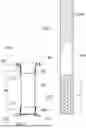
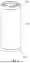
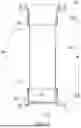
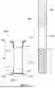
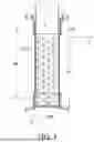
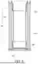
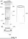
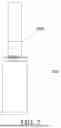

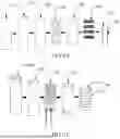
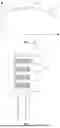

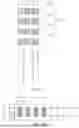

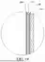
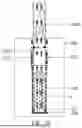
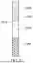
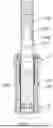


Sources:
- United States Patent and Trademark Office - verify current appl. status at the USPTO↗
Similar patent applications:
- » 20240114965
Aerosol Generation Device Heating Component - » 20200163384
Heating component in aerosol generating devices - » 20220353958
Heating component in aerosol generating devices - » 20260060303
AEROSOL GENERATING DEVICE AND HEATING COMPONENT THEREOF - » 20260060304
AEROSOL GENERATING DEVICE AND HEATING COMPONENT THEREOF - » 20210267268
AN AEROSOL GENERATING COMPONENT FOR A TOBACCO HEATING DEVICE AND A MOUTHPIECE THERFOR
Recent applications in this class:
- » 20260182652 2026-07-02
AEROSOL-GENERATING DEVICE - » 20260182651 2026-07-02
AEROSOL-GENERATING DEVICE - » 20260182650 2026-07-02
AEROSOL-GENERATING DEVICE - » 20260182649 2026-07-02
AEROSOL-GENERATING DEVICE - » 20260182648 2026-07-02
AEROSOL-GENERATING DEVICE - » 20260182647 2026-07-02
AEROSOL GENERATION DEVICE - » 20260182646 2026-07-02
AEROSOL GENERATING DEVICE - » 20260182645 2026-07-02
AEROSOL GENERATING DEVICE - » 20260182644 2026-07-02
HEATER ASSEMBLY FOR AEROSOL GENERATING DEVICE - » 20260182643 2026-07-02
AEROSOL GENERATING DEVICE
Recent applications for this Assignee:
- » 20260157440 2026-06-11
ATOMIZATION CORE, ATOMIZER, AND ELECTRONIC ATOMIZATION DEVICE - » 20260123674 2026-05-07
ELECTRONIC ATOMIZATION DEVICE - » 20260114511 2026-04-30
ELECTRONIC ATOMIZATION DEVICE AND CONTROL METHOD AND APPARATUS THEREOF - » 20260097988 2026-04-09
ATOMIZATION CORE, ATOMIZER, AND ELECTRONIC ATOMIZATION DEVICE - » 20260083173 2026-03-26
ATOMIZATION CORE, ATOMIZER, AND ELECTRONIC ATOMIZATION DEVICE - » 20260083172 2026-03-26
ATOMIZATION CORE, ATOMIZER, AND ELECTRONIC ATOMIZATION DEVICE - » 20260083171 2026-03-26
ATOMIZATION CORE, ATOMIZER, AND ELECTRONIC ATOMIZATION DEVICE - » 20260083169 2026-03-26
ATOMIZATION CORE, ATOMIZER, AND ELECTRONIC ATOMIZATION DEVICE - » 20260083166 2026-03-26
ATOMIZER AND ELECTRONIC ATOMIZATION DEVICE - » 20260078494 2026-03-19
HEATING THIN FILM, ATOMIZATION CORE, AND ATOMIZATION APPARATUS