Tape dispenser with improved components and structures
US20260184530A1
2026-07-02
19/007,513
2025-01-01
Smart Summary: A new tape dispenser has better parts and design to make it easier to use. It can handle different types of adhesive tape, whether they are connected or separate. The dispenser includes features like a non-stick rotating sleeve, two rotating hubs, a hanging hook, and a swingable presser. These improvements make the dispenser more functional and efficient. Overall, it provides added value for users. 🚀 TL;DR
Abstract:
A tape dispenser with improved components and structure for dispensing single/double or triple reverse-conjoined adhesive tape strips, non-reverse-conjoined adhesive tape strips, or for dispensing tape strips from at least one adhesive tape roll without or with a roll of other thin material, each of which incorporates at least one non-stick rotatable sleeve or cylinder, at least two rotatable hubs, a hanging hook, a swingable presser, and with additional enhancements, the improved tape dispenser would offer new functionality, efficiency, and value.
Applicant:
Interested in similar patents?
Get notified when new applications in this technology area are published.
Classification:
B65H35/0033 » CPC main
Delivering articles from cutting or line-perforating machines; Article or web delivery apparatus incorporating cutting or line-perforating devices, e.g. adhesive tape dispensers; Article or web delivery apparatus incorporating cutting or line-perforating devices; Hand-held or table apparatus for delivering pressure-sensitive adhesive tape and affixing it to a surface
B65H2402/412 » CPC further
Constructional details of the handling apparatus; Details of frames, housings or mountings of the whole handling apparatus; Portable or hand-held apparatus details or the parts to be hold by the user, e.g. handle
B65H2701/377 » CPC further
Handled material; Storage means; Handled filamentary material; Tapes Adhesive tape
B65H35/00 IPC
Delivering articles from cutting or line-perforating machines; Article or web delivery apparatus incorporating cutting or line-perforating devices, e.g. adhesive tape dispensers
Description
CROSS-REFERENCE TO RELATED APPLICATION
This application claims priority from U.S. Provisional Patent Application No. 63/622,773, entitled “Tape dispenser with improved components and structures”, filed on Jan. 19, 2024.
BACKGROUND OF THE INVENTION
1. Field of the Invention
The present invention relates to the improvements from previous inventions and providing enhancements with functionality and efficiency essentially forming a new version of the inventions, particularly improvements for the tape dispensers dispensing pressure-sensitive adhesive tape rolls, and more specifically, it incorporates enhancements to the multi-tape dispenser for dispensing reverse-conjoined and/or non-reverse-conjoined adhesive tape-end strips; and dispensing at least one adhesive tape roll without or with a roll of other thin material when the adhesive tape-end strip overlap partially and longitudinally over an edge of other thin material, each of which includes the none-stick rotatable sleeve or cylinder whereon having a raised pattern or etched pattern on the lateral curved surface where the adhesive and/or smooth/non-adhesive side of the tape(s) would roll onto; the rotatable hubs having no protrusion at the base specifically at the outermost base corners; the pivotable and swingable hanging hook, and with other additional enhancements, the improved tape dispenser would be novel, drastically enhance the functionality, and become effectively operational. These enhancements imply a new level of innovation that was not previously part of any tape dispenser. This invention provides efficiency to painters, remodelers, hardwood floor installers, automotive refinish painters, and other users to improve effectiveness in their professions.
2. Description of the Prior Art
The current application primarily relates to the improvements of U.S. Pat. No. 10,662,019B2. Its structural frame and attached components were insufficient to work flawlessly due to the claimed structure and features; therefore, it would need much-needed improvements including drastic modifications and new enhancements to improve performance, functionality, and usability including features, tape paths, tape dispensing directions, and placement of dispensed tape strips; furthermore, and most importantly, it would need improvement for the non-stick rotatable sleeve or cylinder, rotatable hubs, hanging hook, handle, cutting blades, cutting-blade receptacles, substituting part, adding components, and other supporting means that would be incorporated onto the structural frame and attached components that are essential to bringing the tape dispenser to another level of novelty and advancement.
A closely related invention: Double-sided tape dispenser, by Shadrach J. Gibson, U.S. Pat. No. 9,150,377B2, having two rolls of single-sided tape partially roll onto the guide rollers to form overlapping tape strips with the adhesive portions on the opposite sides. Setting up the dispensed tape strips to overlap with each other is puzzling. Dispensing the tape strips may not be smooth or easy, and the overlapped portion may not adhere well due to a lack of pressure to stick together. The guide rollers have flat lateral curved surfaces, therefore the adhesive side of at least one of the tapes would stick onto the smooth lateral curved surfaces and be difficult to roll off. The user must dispense the tape very fast with momentum to reduce friction. Short tape-end strips such as 1″ or 2″ in length cannot be dispensed easily, especially when the tape adhesion is strong. Producing uneven overlapped portions of the dispensed tape strips due to the limited handle control, the overlapping portions may be separated if the tape dispenser is not straight with the dispensing tape direction, and make a loud dragging sound due to the adhesive sides of the adhesive tape sticking to the smooth curved surfaces of the guide rollers. The dispensed tape strips are more likely to interfere with the adjacent structural walls which causes the tape to bend or stick to itself. Since the handle is on the opposite side of the tape rolls, the user may be in an awkward situation controlling the movement of the tape strips that are being dispensed. Hence, the handle also prevents or makes it difficult for the user to dispense and apply the dispensed tape strips at the corner of the ceiling and walls, there would be an open area along the corner of the ceiling and walls, and if the user wants to apply the dispensed tape strips to the ceiling/wall corner, he would have to dispense section by section of the tape strips and manually apply to the corner which is not efficient. The handle could be improved for controllability and ergonomics.
Another closely related invention is The tape dispensing system, by Dewey R. Miller, U.S. Pat. No. 7,028,736B1, where the first and second guide members are attached to the frame to guide the dispensed tape-end strips to overlap partially and to produce adhesive portions on the opposite sides. The dispensed tape-end strip from the first tape roll passes by the first tape guide, and the dispensed tape-end strip from the second tape roll passes by the second tape guide where both tape-end strips should be partially rolled onto each other, or be pressed together. Even if that is accomplished, the adhesive side of the dispensed tape-end strips still sticks to the first and second tape guides due to the lack of non-stick features. The overlapped tape-end strips must also pass through the open gap between the first and second base where the overlapped tape-end strips would touch the hard edge on either side of the bases; therefore, the dispensed overlapped tape-end strips would also stick to either side at the gap between the first base and the second base.
Yet, another closely related invention: The tape dispenser that dispenses overlapping tape and paper structures, by Benny Krog Andersen, U.S. Pat. No. 7,921,896B2, having the adhesive side of the tape passing through certain wall structures that would prevent the flow of tape dispensing and overlapping with the edge of the dispensing paper-end portion. The first portion of the adhesive side of the tape would overlap with an edge of the paper, while the second portion is exposed and has no support; therefore, it would be bent or stuck to the nearby wall structures. It gets worse when a wider tape width is used.
When the adhesive side of a tape strip makes contact with at least one rotatable sleeve or cylinder having a smooth curved surface, it may work fine when a non-stick coat is applied on the smooth curved surface and when the non-stick coat is still new and effective, and also the adhesive side of the tape has less adhesion strength; however, over time, the smooth curved surface of the rotatable sleeve or cylinder deteriorates or becomes dull causing the adhesive side of the tape strip to stick onto the rotatable sleeve or cylinder and, therefore, harder to pull the adhesive tape strip away from the rotatable sleeve or cylinder. Furthermore, the residue from the adhesive tape strips would stick harder and build up onto the smooth curved surface of the rotatable sleeve or cylinder when the adhesive tape rolls are exposed to heat or stored away in warm or humid temperatures for a long period.
In most cases, a pressure-sensitive adhesive tape roll can be dispensed easily with the smooth/non-adhesive side of the tape slides on a bar, a flat surface, onto a rotatable cylinder having a flat curved surface, or does not touch anything at all except at the serrated cutting blade, or the cutting blade's receptacle; however, when dispensing the tape rolls that produce partially overlapped reverse-conjoined tape-end strips or having the adhesive side of at least one tape-end strip rolling partially or fully onto the lateral smooth curved surface of a rotatable sleeve or cylinder, the adhesive side of that dispensed tape-end strip would stick or grip onto the smooth curved surface of the rotatable sleeve or cylinder which creates friction, the resistance that the adhesive side of the tape encounters when rolling laterally over the smooth curved surface of the rotatable sleeve or cylinder; therefore, the tape-end strips would need to be pulled forcefully and noisily to be dispensable. The stronger the adhesion on the tape, the harder it is to dispense the tape-end strip when the adhesive side sticks laterally onto the smooth curved surface of the rotatable sleeve or cylinder. The range of adhesion strength on the tape rolls depends on the brands, storage conditions, how long, how hot or cold, and the width of the tape rolls . . . all of which can affect the dispensing of the tape rolls. In situations where the adhesive side of the tape must roll laterally onto a portion of the smooth curved surface of the rotatable sleeve or cylinder, the user must pull or dispense the tape-end strips very fast with momentum; therefore, he must dispense long strips of tape; unfortunately, dispensing short pieces of tape strips would be difficult or impossible when the adhesive side of the tape sticks to the smooth curved surface of the rotatable sleeve or cylinder. All of the current tape dispensers on the market, such as tape dispensers for dispensing tapes where the adhesive side of a tape rolls onto a lateral flat curved surface of the rotatable sleeve or cylinder creating sticky friction which results in harder for the user to dispense the tape(s).
The manufacturing industry generally recommends those cylinders made of rubber material to reduce stickiness; however, to further analyze the rubber materials, heat can be a big factor affecting the material and loss of the adhesive effectiveness regarding the pressure-sensitive adhesive tapes being in direct contact. In a common situation, for instance, a painting contractor would normally leave the tape dispenser in his car with windows closed for days. The heat inside the car can easily rise to 150*F when it is parked in direct sunray in the afternoon. If bringing the mentioned tape dispenser to normal room temperature, and promptly dispensing the pressure-sensitive adhesive tapes with at least one adhesive side of the tape rolling laterally onto a portion of the smooth curved rubber cylinder, the tape is more likely to stick intensely to the rubber cylinder, and worst when the more sensitive adhesive types of tape are used; packaging tape or duct tape would be even terribly-worst when the adhesive side of the packaging tape or duct tape must roll onto the smooth curved sleeve or cylinder made of rubber or any other material having a smooth curved surface, even when the smooth curved sleeve or cylinder is rotatable.
Teflon is a polymer used in depositing non-stick coating such as for cookware and cooking utensils. Applying a coat of Teflon (Polytetrafluoroethylene), Silicone, Thermolon, or Lol-gel (ceramic coatings) on the smooth curved surface of the rotatable sleeve or rotatable cylinder would not prevent the adhesive side of the tape from sticking. Teflon and the like are non-stick for wet objects such as foods; therefore, it would not be practical for the adhesive side of the tape to roll onto when the Teflon coat is dried.
Tape dispensers available on the market nowadays have at least one rotatable hub for the tape rolls with a 3″ core opening to be loaded onto. The rotatable hubs have protrusions or tape-roll stoppers at the outermost base corners. These protrusions or tape-roll stoppers are means to stop the tape roll which is unnecessary and most likely causes problems when the protrusions or tape-roll stoppers get stuck at sharp corners of the structural wall. The protrusions or tape-roll stoppers at the outermost base corners are the short wall portions extending from the base of the tape-roll hub, specifically at the outer edge portions of the tape-roll hub where they touch the back side of the tape-roll core. When the tape roll is loaded and stopped by the protrusions or tape-roll stoppers, the tape roll would still work fine if it is by itself; however, when the tape roll is configured to be partially overlapped with another tape roll or paper roll, etc., positioning the tape roll to align effectively is important to attain consistency of overlapping portions of the tapes longitudinally. Certain adhesive tape types may have the side of the tape offsetting from the tape-roll core; therefore, aligning those tape rolls to overlap partially and longitudinally with another tape roll may produce less or more overlapping portion which may result in having less adhesive portion of the tape to stick onto a substrate surface. The protrusions or tape-roll stoppers determine the limit and prevent the tape roll from being pushed inward toward the structural wall. The limitation is caused by the protrusions or tape-roll stoppers at the base of the tape-roll hub reducing or increasing the overlapping portions of the reverse-conjoined or with non-reverse-conjoined tape-end strips, or the overlapping portion of the tape and paper, plastic sheeting, or aluminum foil; therefore, creating inconsistency which defeats the purpose of a good tape dispenser for dispensing overlapping tapes, or overlapping tape and paper, plastic sheeting, or aluminum foil. The tape dispenser may be manufactured with more tolerances, particularly the rotatable hub can slide horizontally along its central cylinder or become wobbling, like an out-of-balance tire, due to certain tolerance that is more than reasonable between the backing structural wall and the installed washer/screw on the outer end of the central cylinder. Also, the manufacturers of the adhesive tape rolls produce inconsistent placement of the tape core with the roll-on adhesive tape wound on top of the tape core. In mass production, the tape cores are more likely not aligned evenly with the rolled-on adhesive tapes. Often the tape core and the rolled-on adhesive tape are offset up to 1/16″. Furthermore, friction is caused due to irregularities on the surfaces in contact. Even the smoothest surfaces have minute irregularities in them and these irregularities of the two surfaces interlock or interfere with each other and create friction or drag. When the rotatable hub rotates over a rough structural wall, the protrusions or tape-roll stoppers may prevent the rotatable hub from turning smoothly, especially when the base of the rotatable hub has sharp corners and uneven walls caused by heat or manufacturing errors. There is a need for improvement when at least 2 tape rolls are arranged to produce partially overlapping tape-end strips, or a tape roll is arranged to be overlapped with paper, plastic sheeting, or aluminum foil from a roll.
For a portable tape dispenser, a hanging hook for the tape dispenser to be hang-able when temporarily put aside and ready for use is necessary. In a situation where a pivotable hanging hook rotates, at least partially, around an axis of the handle and the hanging hook is also parallel with the handle axially, hanging the tape dispenser loaded with tape rolls; or with a paper roll or plastic roll onto a user's belt loop, for example, may not hold the tape dispenser properly if the hanging hook is not pointed downwardly in the gravitational direction because the overall weight of the loaded tape dispenser would change the angle of the handle diagonally, if not vertically. In a case when the handle changes to a diagonal position based on the overall weight of the tape dispenser, due to gravity, the hanging hook also changes to a diagonal position. Therefore, if hanging the tape dispenser on a user's belt, for example, the hanging hook at a diagonal position can slide out of the user's belt especially when he climbs up the ladder and steps down the ladder. Therefore, there is a need for the hanging hook to swing in the gravitational direction so that the loaded tape dispenser can be hung with the hanging hook swung downward vertically.
The tape dispensing method can be unconventional under certain circumstances. In the case of dispensing reverse-conjoined tape strips, the adhesive side of the tape should roll onto a portion of the non-stick curved surface of the rotatable sleeve or cylinder and the smooth/non-adhesive side of another tape can roll onto a portion of the smooth curved surface of the adjacent first cylinder. First, to accommodate the rotatable sleeve, there must be a second cylinder next to the first cylinder axially, and the first cylinder needs to be attached directly and perpendicular to a wing extended from the structural wall. How the first cylinder can be incorporated into the structural wall is also a need for a solution. That means having at least one wing under the structural wall is considered for the tape dispenser to work properly and proficiently. Also having a few other methods to incorporate the non-stick rotatable sleeve or cylinder next to the first cylinder axially would be ideal.
When reverse-conjoined tape-end strips, overlapped non-reverse-conjoined tape-end strips, or tape overlaps with a thin material are dispensed, the structural walls are configured to offset each other so that the overlapped portions are consistent and reduce separation. Dispensing tape-end strips should be easy without dragging; users can also dispense any length of tape strips, short or long, without noticeable severe noisy sounds.
Not only can dual tape-end strips be reverse-conjoined with one extra tape roll to be dispensed independently, but all three tape rolls together can be partially overlapped to become triple reverse-conjoined which would become the ideal tape dispenser.
Incorporating additional functional features is essential to enhance the product to a higher level of excellence. Based on the existing structural walls and most existing components, adding a modified component to accept a different roll of material would be a difficult task; however, when it comes to dispensing a roll of tape overlapping with a different material other than another roll of tape, a roll of other thin material such as paper, plastic sheeting, or aluminum foil, etc. becomes a necessity when we see other dispensers on the market do the job but lack extra features that the end-consumers should have. Attaining better quality, more features, ease of use, and cost less to produce, the new enhancements represent a better improvement invention. With just one simple component, a rotatable cylindrical hub replacing an existing rotatable hub, the all-tape dispenser becomes a dispenser for dispensing tape overlapping with other thin materials. Replacing a rotatable hub with a cylindrical rotatable hub would be much simpler than one thought.
Currently, there is no solution to the problem where the adhesive side of the tape must roll onto a rod, rotatable sleeve/cylinder, or a tape presser without the non-stick element or feature. The single tape dispenser for dispensing packaging adhesive tape is available in many different designs on the market; however, when the user has to install a tape roll in only one path so that the non-sticky side of the packaging tape can roll onto a rotatable cylinder and the adhesive side of the tape is held in place with a metal or plastic presser, the dispensed tape-end strip is extended too far from the rotatable cylinder or the tape presser before reaching the cutting blade. There is nothing to hold up that lengthy portion of the dispensed tape-end strip; therefore, the dispensed tape-end strip always bends downward and touches the dirty table or dusty floor. That dispensed tape-end strip would be best discarded because it may not stick well to the substrate surfaces such as shipping boxes or packages. Similarly, on other tape dispensing devices including dispensers dispensing tape overlapping with tape, paper, or plastic, the dispensed portions with the sticky side facing downwardly do not have any non-stick means to hold those dispensed portions up, worse when the adhesive side of the tape has to roll onto a smooth rotatable sleeve or cylinder and is difficult to roll off.
Beneficial solutions, to the problems described above, will be disclosed in the following objects.
OBJECTS OF THE INVENTION
Accordingly, it is a general object of the present invention to provide new and useful improvements, essentially, to enhance the components and structures creating a new type of functional tape dispenser, bringing in new beneficial solutions, and also defining new features that are essential for the utilization of the tape dispenser, and more particularly, the multi-tape dispenser for dispensing reversed-conjoined and/or non-reversed conjoined adhesive tape-end strips from adhesive tape rolls; and/or for dispensing at least one adhesive tape roll, or for dispensing an adhesive tape-end strip overlapping partially and longitudinally over an edge of other thin material coming from a roll so that the user can operate the dispenser effectively and efficiently when dispensing adhesive tapes having the adhesive side of the tape rolling laterally onto a portion of the non-stick rotatable sleeve or cylinder; having at least one rotatable hub without protrusions at the outermost base corners or without tape-roll stoppers at the base of the rotatable hub; having a pivotable and/or swingable hanging hook; having improved structural wall panels and at least one arch wall panel, and having other enhancements for better utilization of dispensing adhesive tape(s), partial overlapping tapes, partial overlapping tape with other thin material, and/or for use in electrical tape dispensing machines.
The first object of the present improvement invention is to solve a problem when the adhesive side of at least one tape roll must roll laterally onto the curved surface of the rotatable sleeve or cylinder that the dispensed adhesive tape-end strips are not supposed to stick onto or are hard to roll off. When a partially overlapped reverse-conjoined tape-end strip or the adhesive side of the tape-end strip must roll onto the rotatable sleeve or cylinder, the non-stick rotatable sleeve, or cylinder, must have a raised pattern or etched pattern incorporated. The raised pattern or etched pattern includes perceptible projections, lumps, or indentations besides having a regular or repeated raised pattern or etched pattern. A non-stick rotatable sleeve installed axially adjacent to the first cylinder, or a non-stick rotatable cylinder installed to the first cylinder, working together side by side axially, can be best for both the overlapped adhesive and smooth/non-adhesive sides of the tape-end strips to roll on and roll off easily. The first cylinder is attached to the wing, and the wing is attached perpendicularly to the structural wall. A non-stick rotatable sleeve or cylinder is necessary to take on the adhesive side of the tape and/or the smooth/non-adhesive side of at least one other tape to roll on and off easily. The non-stick rotatable sleeve is installed onto a second cylinder extended from the first cylinder axially. Therefore, the outside diameter of the first cylinder and the outside diameter of the non-stick rotatable sleeve or cylinder must be the same so that the dispensed reversed-conjoined tape-end strips or single tape-end strips would roll evenly onto the lateral curved surfaces without winkling the tape-end strips. The non-stick rotatable cylinder can be utilized instead of the non-stick rotatable sleeve. The non-stick rotatable cylinder would have a borehole at each base axially, or at least one rod extended from a base for ease of assembling. Embodying the lateral curved surface of the rotatable sleeve or cylinder with a raised pattern or etched pattern, including the perceptible projections, lumps, or indentations, would prevent the adhesive side of the dispensed tape-end strip from sticking hard onto the lateral curved surface of the rotatable sleeve or cylinder which would result in having the same area of the curved surface and specific diameter of the outermost diameter of the rotatable sleeve or cylinder for the at least one side of the adhesive tape to roll onto laterally and yet up to 80% less touching points where the adhesive portion of the at least one tape-end strip contacting the top of the raised pattern or top of etched pattern; therefore would drastically reduce stickiness, friction, drag, and noise. Applying a raised pattern on the smooth curved surface of the rotatable sleeve or cylinder to create ridges, textures, perceptible projections, lumps, or indentations, or removing material from the smooth curved surface by etching methods to create a pattern of ridges, textures, perceptible projections, lumps, or indentations would enhance the current tape dispensing method, and therefore, adding new and better utilization of the tape dispensers.
The raised or etched pattern on the lateral curved surface of the rotatable sleeve or cylinder comprises raised zigzag lines, spiral lines, circular lines, straight lines diagonal lines, crossed lines, weaving lines, or wavy lines, all of which have continuous or broken lines. The raised or etched pattern on the curved surface of at least one rotatable sleeve or cylinder is for a smooth/non-adhesive side and/or adhesive side of at least one tape-end strip from at least one tape roll to roll onto or slide by partially and laterally.
The raised pattern or etched pattern further comprises raised dots, raised letters, raised shapes (round, oval, triangle, square, rectangle, diamond, and trapezoid), raised irregular or repeat wallpaper-like texture, raised sandpaper-like texture, raised brick-like texture, raised wall-texture-pattern-like texture or raised stone-like texture, perceptible projections, lumps, or indentations, in any of which is for the smooth/non-adhesive side and adhesive side of the at least one dispensed tape-end strip from at least one tape roll to roll onto laterally.
The raised pattern or etched pattern includes perceptible projections, lumps, or indentations besides having a regular or repeated raised pattern or etched pattern, that elevates from the lateral curved surface of the non-stick rotatable sleeve or cylinder, is utilized for the tape dispensers dispensing reverse-conjoined and non-reversed conjoined tape-end strips from tape rolls, or for the dispensed adhesive side and the smooth/non-adhesive side of the tape to roll onto. At least one of which can also be incorporated into other tape dispensers including packaging tape dispensers, painter's tape dispensers, electrical tape dispensing machines, or other tape dispensers that lack the non-stick rotatable sleeve or cylinder having raised pattern or etched pattern incorporated onto the curved surface of the rotatable sleeve or cylinder so that the adhesive side of the tape or the smooth/non-adhesive side of the tape can roll at least onto a portion of the lateral curved area which is the curved surface of the rotatable sleeve or cylinder.
Another method to create a raised pattern or etched pattern such as sandpaper grains is by coating a backing with a resin and statistically charging grains to attract to the adhesive resin such as hide glue which results in having sandpaper on the curved surface of the non-stick rotatable sleeve or cylinder; said grains may be a natural mineral such as garnet or from synthetic one like aluminum oxide, aluminum zirconia or silicon carbide, in any technique and method of application would give the non-stick rotatable sleeve or cylinder having sandpaper grains that prevent the adhesive side of the tape from sticking upon.
To be functional and effective, the non-stick rotatable sleeve or cylinder is preferably made from rigid plastic materials, or metal materials such as aluminum, chrome, stainless steel, or alloy combinations also work well, but the costs for manufacturing would be higher if compared with plastic materials. Rubber material such as silicone rubber would be the least desirable due to heat/cold effects, even with a raised or etched pattern incorporated. Incorporating a raised pattern onto the curved surface of the non-stick rotatable sleeve or cylinder made from rigid plastic material would be an ideal and easier to produce the raised pattern of ridges or texture on the curved surface; a different way to produce a certain pattern is the etching methods by wet or dry using chemical solution or gases to create patterns or by other means.
Having the non-stick rotatable sleeve or cylinder with a raised pattern or etched pattern incorporated onto the lateral curved surface would be ideal for the tape dispenser to dispense pressure-sensitive adhesive tape rolls when the adhesive side of the tape must roll laterally onto the curved surface of the non-stick rotatable sleeve or cylinder. As a result, incorporating the raised pattern or etched pattern onto the non-stick rotatable sleeve or cylinder is essential. The improved tape dispenser can dispense any adhesive tape with any adhesion strength.
The second object of the present improvement invention is to position the non-stick rotatable sleeve axially next to the first cylinder where the first cylinder is connected to the rear end portion of the first wing. The second cylinder is extended from the inside base of the first cylinder and is smaller in diameter than the first cylinder. The second cylinder is for the non-stick rotatable sleeve to be installed onto and rotatably fastened in place by a screw or with a washer. The first cylinder has the same outside diameter as the outside diameter of the non-stick rotatable sleeve. The non-stick rotatable sleeve and the first cylinder accommodate both the smooth/non-adhesive side from at least one tape roll and the adhesive side from at least one tape roll simultaneously. Secondly, the first cylinder can be hollowed for the rod extending from the non-stick rotatable cylinder to be inserted into the hollowed first cylinder, and fastened to the hollow first cylinder by a screw or with a washer. Thirdly, in another situation, the first cylinder has female threads incorporated so that a long bolt can be inserted through the non-stick rotatable sleeve and fastened to the female-threaded first cylinder. When the non-stick rotatable sleeve or cylinder is rotatably installed next to the first cylinder axially, the smooth/non-adhesive side and the adhesive side of the tape(s) can roll onto the lateral curved surface, simultaneously, and roll off easily without stickiness, friction, drag, and noise.
The third object of the invention is to solve a problem when the installed tape rolls cannot be pushed further back toward the structural walls specifically the first and second wall panels because of the protrusions or tape-roll stoppers at the outermost base corners of the rotatable hubs. Having no protrusions or tape-roll stoppers at the outermost base corners of the rotatable hubs allows the tape rolls to be adjustable when in a situation where the rotatable hubs have too much tolerance and slide horizontally on the axial cylinders extended from the first or second wall panel where the rotatable hubs are installed.
In a situation where one tape-end strip should align to overlap partially and longitudinally with another tape-end strip, having no protrusions or no tape-roll stoppers at the base of the rotatable hubs would alleviate the concern of the uneven placement of the tape wound onto the tape-roll core. Adjusting the tape rolls to align and overlap correctly would make loading the tape rolls easier. Therefore, a need exists for new and improved rotatable hubs where the tape rolls can be installed and be adjustable from the structural walls where the rotatable hubs are installed even when there is too much tolerance between the rotatable hub and the structural wall. The structural wall can also help to reduce or eliminate the rotatable hubs from wobbling when rolling, yet the tape rolls are still rotatable without any drag or friction. By having no protrusion or tape-roll stoppers at the base of the rotatable hubs, specifically at the outer edge portions of the rotatable hubs where they touch the back side of the tape-roll cores, the tape rolls can be pushed closest to the back wall, or they can be adjustable to align with each other, or other thin material coming from a roll. The operator can adjust the tape-roll placement on the rotatable hubs to attain a desirable overlapping portion of the reverse-conjoined and/or non-reverse conjoined tapes, or an overlapping portion of the tape and other thin material including but not limited to paper, plastic sheeting, aluminum foil, etc. In such a case, when a roll of other thin material is utilized, a rotatable cylindrical hub is incorporated to replace the rotatable hub installed on the second wall panel.
The fourth object of the present invention is to implement improvement for the hanging hook as it is much needed to correctly position the hanging hook in the right direction, which is pointing to the gravitational direction as when the tape dispenser is hung, that is, a new functional hanging hook that can pivot partially around an axis of the handle and also swingable on the left or right side of the handle so that when the tape dispenser is loaded with tape rolls, the hanging hook should be swung toward the gravitational direction. Having the hanging hook swing downwardly in a gravitational downward position, the tape dispenser would surely hang in the correct position. An adaptor for the hanging hook is incorporated and configured so the hanging hook would pivot and swing downward on the left or right side of the handle (4). The tape dispenser should be hang-able on the user's belt loop, jean pocket, and on the ladder for convenience whether the user is on the ladder or standing on the floor, he should be able to hang the tape dispenser by his side, ready for use.
The fifth object of the present invention is incorporating a swingable presser with a non-stick rotatable sleeve or cylinder installed. The swingable presser also has a torsion spring installed at the base so that the swingable presser can swing forwardly which causes the non-stick rotatable sleeve or cylinder to press against the adhesive or smooth/non-adhesive side of the dispensed tape-end strips, especially at the partially overlapped reverse-conjoined tape-end strips, or tape overlaps with other thin material, to ensure the overlapped portions stick to each other well, and to hold the dispensed portion in place. The non-stick rotatable sleeve or cylinder has a raised pattern or etched pattern on the curved surface so that the adhesive side of the tape-end strip can roll on and roll off easily. The swingable presser has a trigger incorporated so the user can use his finger to pull the swingable presser backward so the user can set up the tape strips in certain ways. In certain configurations, the swingable presser can be a flexible member without a non-stick rotatable sleeve or cylinder installed. Said flexible member can be installed at the front portion of the cutting blade where the dispensed tape strips are cut and pressed onto the intended substrate surface.
The sixth object of the present invention is that the current straight handle can be replaced with a slanted curved handle with curvy finger grips and positioned on top or to the left side of the first wall panel. The front end of the slanted curved handle having a horizontal member extends toward the right side; and is connected to the extended neck portion over the second cutting-blade receptacle, behind the second cutting-blade receptacle, connected to the upper portion of the first wall panel, or the upper portion of the arch wall panel. The front end of the slanted curved handle can be connected to the exposed left-end portion of the second cutting-blade receptacle. The slanted curved handle is positioned behind the first and second wall panels when the first wall panel is arranged over the second wall panel as when the tape dispenser is set in the free-standing position. The rear end of the slanted curved handle when being without or with a horizontal member extends toward the right side and is connected perpendicularly to the rear portion of the second wall panel, or the arch wall panel. The slanted curved handle can be positioned over or behind the rotatable cylindrical hub. The rear stand foot is perpendicular to the second wall panel and has an extension extending toward the front which becomes a secondary stand foot supporting the roll of other thin material, and also be used as a fixed hanging hook.
The seventh object of the present invention is substituting the rotatable hub installed on the left side of the second wall panel with a rotatable cylindrical hub so that a roll of other thin material such as paper, plastic, aluminum foil, etc. can be loaded onto. The rotatable cylindrical hub has a raised or etched pattern on the curved surface having patterns parallel to the axis that would fit inside the core opening of a roll of other thin material. The rotatable cylindrical hub has a compression spring loaded within the hollow space axially, or a spring-wave washer loaded at the base. The rotatable cylindrical hub has no protrusion or tape-roll stoppers at the outermost portion of the base. The rotatable cylindrical hub may have at least one wire-tension or leaf-tension spring incorporated onto the curved surface.
The eighth objective of the present invention is while the tape dispenser is configured for the tape installed on the right side of the first wall panel to be reverse-conjoined with the tape installed on the left side of the second wall panel, or the tape rolls installed on the right and left side of the first wall panel are arranged to be reverse-conjoined with the tape installed on the left side of the second wall panel producing partially overlapped tape-end strips; yet in another ideal arrangement, the dispensed tape-end strip from the tape roll on the right side of the first wall panel is overlapped with the dispensed portion of the roll of other thin material on the left side of the second wall panel, the remaining tape roll on the left side of the first wall panel would be available to be dispensed by itself.
The ninth object of the present invention is using the tape dispenser for dispensing partially overlapped reverse-conjoined tape strips for use in offices, schools, homes, and other places for posting bulletins, notes, pictures, drawings, etc. instead of pushing the thumb tags or pins onto walls. Pressure-sensitive adhesive tape rolls having different adhesion strengths can be utilized for particular purposes. The tape dispenser has a non-stick rolling sleeve or cylinder to line up the tape strips and guide the tape strips to affix together partially and longitudinally. The reverse-conjoined tape trips are produced by two or three tape rolls arranged to overlap partially with each adhesive side on the opposite side.
The tenth object of the present invention is having a mini-version of the partially overlapped reverse-conjoined tape dispenser using office-type tapes, or similar in small rolls, and possibly pressure-sensitive adhesive tapes for use in offices, schools, or homes for the purpose similar to the ninth object above. The reverse-conjoined tape trips are produced by two or three tape rolls arranged to overlap partially with each adhesive side on the opposite side. The mini-version of the tape dispenser has a non-stick rolling sleeve or cylinder.
SUMMARY OF THE INVENTION
By these aims and objectives, the present invention provides improvements for tape dispensers and more particularly enhancements for the multi-tape dispenser for dispensing reverse-conjoined tape-end strips or non-reversed-conjoined tape-end strips, and for dispensing tape overlapped with other thin material, in any of which, including enhancements on the structural walls, attached components, and new apparatus. Incorporating new elements, features, and capabilities to enhance the current tape dispensers, bring in new technology, and create a new use of the tape dispensers by adding, substituting, or modifying certain parts to create better products with more value. Incorporating a non-stick rotatable sleeve or cylinder having a raised pattern or etched pattern on the lateral curved surface so that even the adhesive side of the tape with any adhesion strength can roll on directly and easily roll off from the lateral curved surface of the non-stick rotatable sleeve or cylinder; having a non-stick rotatable sleeve or cylinder installed axially next to the first cylinder which is a smooth cylinder providing a structural connection while providing even curved surfaces for the partially overlapped adhesive and smooth/non-adhesive side of the tape-end strips to roll onto and roll off easily, or for the overlapped tape-end strips with other material to roll onto and roll off easily. The rotatable hubs have no protrusions or tape-roll stoppers at the outermost base corners; therefore the tape rolls are adjustable to align and set up the overlapping portion of the tapes or tape with other thin material, even when each rotatable hub has a few millimeters of tolerance that allows the rotatable hub to slide horizontally. The handle has a pivotable hanging hook that can swing downwardly from the left or right side of the handle pointing to the gravitational direction. The swingable presser is incorporated to press onto the overlapped portions of the tape or tape and other thin material to hold them in place. The rotatable hub on the left side of the second wall panel is substituted by the rotatable cylindrical hub as an optional configuration for dispensing at least one tape roll and a roll of other thin material, including but not limited to paper, plastic sheeting, or aluminum foil.
Accordingly, this invention's main object is to provide tape dispensers of the characters described above that are technically simple to mass produce and simple to assemble, add more value and ease of use, accomplish better results, and save time, as will be described in connection with the accompanying drawings.
BRIEF DESCRIPTION OF THE DRAWINGS
These and other objects and advantages of the present improvement invention will become more fully apparent by reference to the following detailed description when read in conjunction with the accompanying drawings with reference numerals indicating corresponding parts throughout the several views, wherein:
FIG. 1 is a 3-dimensional view of the tape dispenser from the upper front-left angle.
FIG. 2 is a 3-dimensional view of the tape dispenser from the upper front-right angle.
FIG. 3 is a 3-dimensional view of the tape dispenser from the lower rear-left angle.
FIG. 4 is a right-side view showing the location of the front-right tape roll and tape path.
FIG. 5 is a left-side view showing the location of the rear-left tape roll and tape path arranged to be a dual reverse-conjoined with the front-right tape roll (FIG. 4), while the front-left tape roll has an upward tape path to be dispensed as a single tape.
FIG. 6 is a left-side view showing the front-left tape roll having the same axis as the front-right tape roll (FIG. 4) and the rear-left tape roll having a tape end strip dispensed and swung forward to overlap with the 2 dispensed front tape strips.
FIG. 7 is a left-side view showing the tape dispenser hung accordingly when the tape rolls are loaded onto a tape dispenser, and the hanging hook is swung downward in the gravitational direction.
FIG. 8 is a 3-dimensional view of the non-stick rotatable sleeve having one of the raised patterns.
FIG. 9 is a 3-dimensional view of the non-stick rotatable cylinder with an extended rod that can be rotatably inserted into a hollowed mating cylinder.
FIG. 10 is a 3-dimensional view of the rotatable hub.
FIG. 11 is a 3-dimensional view of the tape dispenser from the lower rear-left angle showing a substituted rotatable cylinder hub, a swingable presser, and a straight handle with a swingable hanging hook.
FIG. 12 is a 3-dimensional view of the tape dispenser from the lower rear-left angle showing a substituted rotatable cylindrical hub, a swingable presser, and a curved handle.
FIG. 13 is a 3-dimensional view showing the removable cutting blade.
FIG. 14 is a 3-dimensional view showing the removable cutting-blade adaptor.
DESCRIPTION OF THE PREFERRED EMBODIMENTS
Referring now in detail to the drawings, there is shown in FIG. 1& 2 an upper front-left view of the tape dispenser showing the first wall panel (1), second wall panel (2), and at least one arch wall panel (3) radiating axially from the front rotatable hubs (8 & 9) and/or the rear rotatable hub (10) connecting first wall panel (1) and second wall panel (2). The handle (4) has a thumb rest (5) positioned on the upper front portion of the handle (4). The hanging hook (7) is installed to the adaptor (6) and in turn, the adaptor (6) is inserted into the rear end of the handle (4) and locked in place by having 2 retainers snapping onto the square-retainer hole (22) on the left and right side of the handle (4). The adaptor (6) and the attached hanging hook (7) are configured to hang the tape dispenser based on the overall weight of the tape dispenser. The hanging hook (7) is swung in the gravitational direction which is vertically downward (as shown in FIG. 7). The hanging hook (7) is partially rotatable along the axis and swingable when it is positioned on the left or right side of the handle (4). The extended neck portion (23) is the connection between the thumb rest (5) and the upper front portion of the first wall panel (1) or the upper-front portion of the arch wall panel (3), another extended neck portion (24) is the connection between the rear end portion of the handle (4) and the upper portion of the second wall panel (2) or at the upper portion of the rear arch wall panel (not shown). The square holes (22) on the left and right side near the rear end of the handle (4) are for the retainers on the adaptor (6) to be inserted into the rear end of the handle (4) and snapped into the square holes (22) from the inside. The front-right rotatable hub (8) on the first wall panel (1) is for a tape roll to be installed for dispensing the tape-end strip that is arranged to partially overlap and reverse-conjoin with the tape-end trip dispensed from the rear-left tape roll installed on the rotatable hub (10) on the second wall panel (2) producing dual reverse-conjoined tape strips, while the front-left tape roll loaded on the rotatable hub (9) on the front-left side of the first wall panel (1) is for dispensing tape-end strips by itself. To produce triple reverse-conjoined tape strips, the front-right tape roll installed on the rotatable hub (8) and the front-left tape roll installed on the rotatable hub (9) must be set up first and second, reflectively, so that the rear-left tape roll installed on the rotatable hub (10) can be placed evenly to overlap with the two front tape rolls installed on the rotatable hubs (8 & 9) while having a center portion of the tape-end strip dispensed from the rear-left tape roll installed on the rotatable hub (10) with the adhesive portion of the tape exposed. The first cutting-blade receptacle (14) has the first cutting blade (15) inserted, snapped on, or fastened on for cutting the partially overlapped reverse-conjoined or with non-reverse-conjoined tape strips. The second cutting-blade receptacle (16) has the second cutting blade (17) inserted for cutting tape-end strips dispensed from the tape roll installed on the rotatable hub (9) when it is set up to dispense by itself. The first cylinder (13, FIG. 2) is partially connected to the rear portion of the first wing (11). The second cylinder (19, FIG. 1) is extended axially from the inside base of the first cylinder (13) which is axially hidden inside the non-stick rotatable sleeve (20) and can only be seen at the front end of the non-stick rotatable sleeve (20) where a screw, or with a washer is fastened to hold the non-stick rotatable sleeve (20) in place. The first wing (11) is attached perpendicularly to the lower-right portion of the first wall panel (1) and the second wing (12) is attached perpendicularly to the lower-left portion of the first wall panel (1). The bottom of the first wing (11) and second wings (12) connect and have the same bottom plane having 2 parallel engraved lines (31a & 31b, FIG. 3), dashed lines, or a square shape (not shown) incorporated to indicate the placement of the inside edges of the dispensed tape-end strips. The bottom plane is also utilized for the dispensed tape-end strips to stick to temporarily.
The cantilever (18, FIGS. 1 & 3) is for the tape-end strip dispensed from the tape roll loaded onto the rotatable hub (10) to roll onto which provides an angle for the tape strip to overlap partially and longitudinally with the tape-end strip dispensed from the tape roll installed on the rotatable hub (8) when the dispensed tape-end strip is set up to be overlapped and reverse-conjoined at the first cylinder (13) and the non-stick rotatable sleeve (20). The front arch wall panel (3) or the rear arch wall panel (not shown) positioned on the second wall panel (2) is substitutable with connecting short walls, connecting cylinders, or wavy wall panels (not shown) any of which is perpendicular to the first and second wall panel (1 & 2). The cantilever (18) is positioned at the lower-front portion of the second wall panel (2) and is perpendicular and projected horizontally from the lower-front portion of the second wall panel (2). The cantilever (18) is positioned at an angle over the non-stick rotatable sleeve (20) so that the tape-end strip dispensed from the rear-left tape roll on the rotatable hub (10) would be pressed to stick partially at the first cylinder (13) and the adjacent non-stick rotatable sleeve (20). The cantilever (18) is parallel to the first cylinder (13) and the non-stick rotatable sleeve (20). The distance (38, FIG. 4) between the cantilever (18) and the nonstick rotatable sleeve (20) is for the user's finger/thumb to pull the tape-end strip between the cantilever (18) and the non-stick rotatable sleeve (20). The cantilever (18) is pre-configured in case a second non-stick rotatable sleeve (20) is needed to be installed onto the cantilever (18). The non-stick rotatable sleeve (20) has a raised or etched pattern on the lateral curved surface.
In another preferred embodiment, the housing structure has the first wall panel (1), the second wall panel (2), the front arch wall panel (3), and the rear arch wall panel (not shown). The first wall panel (1) is offset from the second wall panel (2) having surfaces on different planes, and surfaces being paralleled with one another. The front arch wall panel (3) has a radius generating from the center of the front rotatable hub (8) and the rear arch wall panel (2) has a radius generating from the rear rotatable hub (10). The front arch wall panel (3) and the rear arch wall panel are substantially perpendicular to the first wall panel (1) and the second wall panel (2). The rear arch wall panel is connected to the second wall panel (2) at an upper rear portion and to the rear portion of the front arch wall panel (3), and connected to the lower rear portion of the first wall panel (1).
The first cutting blade (15) is pre-inserted, fastened by a screw, or snapped and locked onto the first cutting-blade receptacle (14). The first wing (11) and the second wing (12) become one member having a flat bottom with 2 indented lines or a square shape indicating alignments for the edge of the tape to stick to temporarily. The first cylinder (13) is connected to the rear portion of the first wing (11). It has a smooth lateral curved surface and is intended for the non-adhesive side of the tape to roll on. Adjacent to the first cylinder (13) axially is an extended second cylinder (19) extending from the inside base of the first cylinder (13) where the non-stick rotatable sleeve (20) is installed. Therefore, adjacent axially to the first cylinder is the non-stick rotatable sleeve (20) which has a raised pattern or etched pattern on the lateral curved surface for the adhesive and non-adhesive side of the tape to roll on. When the rear stand foot (21) and the tape roll installed on the rotatable hub (10) are placed on a horizontal surface, the bottom point of tangency of the tape roll and the rear stand foot support the tape dispenser to be free-standing diagonally. The non-stick rotatable sleeve (20) and the first cylinder (13) combination are utilized for the hand-operated tape dispensers for dispensing at least one adhesive tape roll or dispensing a combination of tape and paper or plastic coming from a roll; and for the electrical tape dispensing machines that dispenses at least one adhesive tape roll.
FIG. 3, the bottom-rear-left view of the tape dispenser showing the bottom view of the first wing (11) next to the second wing (12) where both have the same flat bottom with 2 indented lines (31a & 31b) are shown to indicate the placement of the inside edges of the 2 tape-end strips dispensed from the front-right tape roll on the rotatable hub (8), and from the front-left tape roll on the rotatable hub (9) when the tape rolls are set up for dispensing triple reverse-conjoined tape-end strips. The bottom of the first cutting-blade receptacle (14) also has 2 indented dashed lines (32a & 32b) that are lined up straight with the 2 indented solid or dashed lines at the bottom of the first wing (11) and second wing (12). The bottom of the first wing (11) and second wing (12) are for the adhesive side of the tape to stick onto, and help prevent the tape-end strips from swinging downward. The user can also gently press the adhesive side of the tape onto the bottom of the first cutting-blade receptacle (14) so that tearing the tape-end strips at the cutting blade is more feasible. Loading the tape rolls onto the rotatable hubs (8, 9 & 10) to produce the dual or triple reverse-conjoined tape strips will be described in FIGS. 4, 5 & 6.
The first cylinder (13) is incorporated as part of the first wing (11) and has a second cylinder (19, FIG. 3) extended axially from the inside base of the first cylinder (13). The second cylinder (19) is for the non-stick rotatable sleeve (20) to be installed and fastened by a screw or with a washer. The first wing (11) is attached perpendicularly to a bottom rear portion on the first side of the first wall panel (1), and the second wing (12) is attached perpendicularly to a bottom rear portion on the second side of the first wall panel (1). The bottom of the first wing (11) and the bottom of the second wing (12) have the same bottom plane. The bottom plane of the first wing (11) and second wing (12) has two engraved lines (30), dashed lines, or a square shape (not shown) indicating two locations for tape alignments. The bottom plane is also utilized for the adhesive side of a tape to temporarily stick to, which also helps to prevent the tape-end strips from swinging downwardly while not in use. The first wing (11) has a first cylinder (13) incorporated into the rear portion of the first wing (11). The first cylinder (13) is incorporated into the rear portion of the first wing (11) having an exposed curved surface and a portion of the first cylinder (13) is connected to the rear portion of the first wing (11). The first cylinder (13) has a second cylinder (19) extended axially from the base of the first cylinder (13), and the second cylinder extended from the base of the first cylinder (13) is hollow or partially hollow. The second cylinder (19) has a smaller outside diameter than the first cylinder (13). The second cylinder (19) is for the rotatable sleeve (20) to be installed onto; said the rotatable sleeve (20) has a raised pattern or etched pattern incorporated onto the curved surface; said the exposed curved surface of the first cylinder (13) having the same radius as on the outermost radius of the raised pattern or etched pattern on the curved surface of the rotatable sleeve (20). The exposed curved surface of the first cylinder (13) is for the smooth/non-adhesive side of the tape to roll onto laterally. The rotatable sleeve (20), having a raised pattern or etched pattern, is for the adhesive side and/or the smooth/non-adhesive side of the tape-end strip to roll onto laterally. The first cylinder (13) is hollow or partially hollow. The second cylinder (19) extended from the base of the first cylinder (13) axially is for the rotatable sleeve (20) to be installed by a crew or with a washer.
In an alternative embodiment, the first cylinder (13) is incorporated into the rear portion of the first wing (11) having an exposed curved surface, and a portion of the first cylinder (13) is connected to the rear portion of the first wing (11). The first cylinder (13) is hollow or partially hollow or female threaded inside the hollow first cylinder (13). The first cylinder (13) is for the non-stick rotatable sleeve (20) to be rotatably installed axially to a base of the first cylinder (13) by a bolt or self-tapping screw fastened axially through the hollow rotatable sleeve (20) and into the female threaded portion of the first cylinder (13). The rotatable sleeve (20) has a raised or etched pattern on the curved surface. The exposed curved surface of the first cylinder (13) has the same radius as the outermost radius of the raised pattern or etched pattern on the curved surface of the rotatable sleeve (20). The exposed curved surface of the first cylinder (13) is for the smooth/non-adhesive side of the tape to roll onto laterally. The non-stick rotatable sleeve (20) having a raised pattern or etched pattern is for the adhesive side and the smooth/non-adhesive sides of the tape-end strips to roll onto laterally.
In another alternative embodiment, the first cylinder (13) is incorporated as part of the first wing (11) at the rear portion. The first cylinder (13) has an exposed curved surface and a portion of the first cylinder (13) is connected to the rear portion of the first wing (11). The first cylinder (13) is hollow; said the hollow first cylinder (13) is for the non-stick rotatable cylinder (20a) which has an extended rod (20b) to be axially inserted into the hollow first cylinder (13), and fasten to hole in place by a screw or with a washer; said the non-stick rotatable cylinder (20a) having a raised pattern or etched pattern on the curved surface. The exposed curved surface of the first cylinder (13) has the same radius as the outermost radius of the raised pattern or etched pattern on the curved surface of the non-stick rotatable cylinder (20a, FIG. 8). The exposed curved surface of the first cylinder (13) is for the smooth/non-adhesive side of the tape to roll onto laterally. The non-stick rotatable cylinder having a raised pattern or etched pattern is for the adhesive side of the tape and the smooth/non-adhesive side of the tape to roll onto a portion of the non-stick rotatable cylinder laterally; said the rod extended axially from the base of the non-stick rotatable cylinder is hollow or partially hollow and is for inserting into the hollow first cylinder; said the inserted rod is rotatably fastened to the first cylinder (13) by a crew or with a washer.
The gap between the inside base of the first cylinder (13) and the adjacent inside edge of the non-stick rotatable sleeve (20) is offset to the right side of the first wall panel (1) and the inside edge of the non-stick rotatable sleeve (20) is aligned with the left side of the second wall panel (2). The inside edge of the rear tape roll installed on the second wall panel (2) is aligned with the inside edge of the non-stick rotatable sleeve (20).
Loading the first tape roll (47, FIG. 4) onto the rotatable hub (8), at the front-right side of the first wall panel (1), is always the first step to start setting up for dispensing dual or triple reverse-conjoined tape-end strips. The front-right tape roll (47) installed on the rotatable hub (8) is set up to rotate clockwise dispensing the tape-end strip (25) looping onto the first cylinder (13) and also onto the inside portion of the non-stick rotatable sleeve (20, FIG. 2), the user then pulls the tape-end strip (25) toward the front about 2 inches, bend a portion of the adhesive side of the tape end forming a short upward U-turn so that the bent portion having the adhesive side of the tape-end strip can temporarily stick to the bottom surface of the first wing (11, FIG. 3) with the inside edge of the tape-end strip aligned with the imprinted line (31a in FIG. 3) on the same side, or to the bottom of the cutting-blade receptacle (14) with the inside edge of the tape-end strip aligned with the imprinted line (32a, FIG. 3) on the same side. The result is having the dispensed portion of the tape-end strip (50). FIG. 4 also shows the cylinder (53) incorporated onto the right side of the first wall panel (1) where the rotatable hub (8) is rotatably installed. The finger-access opening (38) is a clearance space for the user to set up the tape-end strips on both sides of the first wall panel (1).
For dispensing dual reverse-conjoined tape-end strips, install the front-right tape roll (47) onto the rotatable hub (8)—as described in FIG. 4 above. Next, see FIG. 5, to install the rear-left tape roll (49) onto the rotatable hub (10) in the clockwise direction, so that the tape-end strip (27) will loop onto the cantilever (18) with the smooth/non-adhesive side of the tape gliding onto the cantilever (18) and the user can pull the tape-end strip (27) backward at an angle of approximately 3 inches long without touching the non-stick rotatable sleeve (20); then determine the inside edges of the tape-end strips (27) to overlap ¼ inch before swinging forward to place the rear tape-end strip (51) partially and longitudinally overlap with the previously dispensed tape-end strip (50) from the installed tape roll (47) installed on the rotatable hub (8) already been placed onto the bottom of the first wing (11, FIG. 3) and also described in FIG. 4. The front-left tape roll (48) installed on the rotatable hub (9) is set up to rotate counter-clockwise and the tape-end strip (26) is being pulled upward and affixed at the second cutting-blade receptacle (16), and be cut at the second cutting blade (17) positioned at the front-left side of the extended neck portion (23). Summarily, the front-right tape roll (47, FIG. 4) is arranged to be reverse-conjoined with the rear-left tape roll (49, FIG. 5) at the overlapped tape-end strips (50 & 51) longitudinally and cut at the first cutting blade (15) and the front-left tape roll (48) is set up to be dispensed upward independently and cut at the second cutting blade (17). FIG. 5 also shows the cylinders (54 & 40) incorporated onto the left side of the first wall panel (1) and second wall panel (2) where the rotatable hubs (9 & 10) are rotatably installed, respectively. The tape-end strips coming from the tape rolls become overlapped partially and longitudinally when at least one tape roll is loaded from one side of the housing structure or both sides.
For dispensing triple reverse-conjoined tape-end strips, first, install the front-right tape roll (47) onto the rotatable hub (8)—as described in FIG. 4. Next, see FIG. 6, install the front-left tape roll (48) onto the rotatable hub (9) to be dispensed in the counter-clockwise direction producing tape-end strip (26). Notice the tape-end strip (25) was previously installed on the right side of the first wall panel (1). The dispensed tape-end strip (26) from the front-left tape roll (48) on the rotatable hub (9) is pulled backward about 2 inches away from the non-stick rotatable sleeve (20). The user then swings the tape-end strip (26) downward and loops the tape-end strip (26) laterally onto the non-stick rotatable sleeve (20) and swings toward the front while bending a portion of the adhesive side of the tape end forming a short upward U-turn so that the bent portion having the adhesive side of the tape-end strip can temporarily stick to the bottom surface of the second wing (12) with the inside edge of the tape-end strip (26) aligned with the imprinted line (31b, FIG. 3) on the same side, or to the bottom of the cutting-blade receptacle (14) with the inside edge of the tape-end strip aligned with the imprinted line (32b, FIG. 3) on the same side. There should be a ½ inch gap between the inside edge of the tape-end strip (26) dispensed from the front-left tape roll (48) loaded onto the rotatable hub (9) and the inside edge of the tape-end strip (25) dispensed from the front-right tape roll (47) loaded onto the rotatable hub (8). Next, install the rear-left tape roll (49) onto the rotatable hub (10) in the clockwise direction, so that the tape-end strip (27) with the smooth/non-adhesive side of the tape loops onto the cantilever (18) and the user can pull the tape-end strip (27) backward at an angle of approximately 3 inches long without touching the non-stick rotatable sleeve (20); then determine the inside edges of the tape-end strips (25 & 26) having a ½ inch space between both front tape rolls before swinging the rear tape-end strip (27) from tape roll (49) forward and place the rear tape-end strip (27) from the rear tape roll (49) to partially and longitudinally overlap evenly with the dispensed tape-end strips (25 & 26) from the installed tape roll (47 & 48) installed on the rotatable hub (8 & 9) already been placed onto the bottom of the first wing (11 & 12, FIG. 3). The result is the tape-end strip (50) dispensed from the front-right tape roll (47) and the tape-end strip (52) dispensed front-left tape roll (48) are arranged having a ½ inch longitudinal space between the inside edges of the tape rolls (47 & 48) so that the rear-left tape roll (49) having tape-end strip (51) overlapping with the inside edges forming reverse-conjoined consistently with the front-right and front-left tape-end strips (50 & 52). Summarily, the front tape rolls on the left side and the right side of the first wall panel (1) having the dispensed tape strips (25 &/26) partially loop onto the first cylinder (13) and the non-stick rotatable sleeve (20); then extend toward the front producing tape-end strips (50 & 52); the rear-left tape roll on the second wall panel (2) having the tape-end strip (27) dispensed and partially looped onto the cantilever (18); then partially looped onto a portion of the front-right tape strip and front-left tape strip at the non-stick rotatable sleeve (20) to overlap evenly with the 2 tape-end strips (25 & 26) which produces triple reverse-conjoined tape-end strips (50, 52 & 51).
In another arrangement, the tape rolls are arranged to have the adhesive side of the tape-end strip (25, FIG. 4) from the tape roll (47) on the front-right wall panel (1) facing downward, and the adhesive side of the tape-end strip (26, FIG. 5) from the tape roll (48) on the front-left wall panel (1) facing upward; finally, the adhesive side of the tape-end strip (27, FIG. 6) from the tape roll (49) on the rear-left wall panel (2) also facing upward to overlap evenly with the 2 front tape strips, and to form 2 non-reverse-conjoined tape-end strips with a reverse-conjoined tape-end strip.
The dual or triple-overlapped reverse-conjoined tape-end strips are partially and longitudinally formed from the tape rolls loaded from one or both sides of the housing structure. The tape rolls are arranged horizontally as the front and rear tape rolls; vertically as the top and bottom tape rolls, or diagonally as the upper and lower tape rolls positioned on the housing structure, in any of which to dispense tape-end strips partially and longitudinally overlapped reverse-conjoined tape-end strips and a single tape roll dispenses by itself without being conjoined.
The arrangements of the tape rolls above are reversed on both left and right sides, including the housing structure; fixed and rotatably installed components are also reversed to attain other embodiments for left or right-hand configurations.
Referring to FIG. 7, the hanging hook (7) is installed onto the adaptor (6), in turn, the adaptor (6) is inserted and snapped into the rear end of the handle (4) and locked in place by 2 retainers hooking Into the square-retainer hole (22) on the left and right side near the rear end of the handle (4). The adaptor (6) provides means for the hanging hook to pivot axially and also become swingable on the left or right side of the handle (4) based on the overall weight of the tape dispenser, including the loaded tape rolls when the handing hook (7) is positioned on the left or right side of the handle (4), it can be swung counter-clockwise and pointed downward in the gravitational direction; when the hanging hook (7) is on the right side of the handle (4), it can be turned clockwise and pointed downward in the gravitational direction when the tape dispenser is loaded with tape rolls. The hanging hook is swung downward in the gravitational direction, which is intentional to prevent the tape dispenser from sliding out of the hanging position such as a ladder, the user's belt, or Jeans pocket. The hanging hook (7) becomes swingable and points toward the gravitational direction which is vertically downward to prevent the tape dispenser from slipping out of the hanging means. The hanging hook (7) is configured to pivot from the resting position on the lower-left position under the rear-end portion of the handle (4), pivot to the opposite side, and stop on the right side of the extended neck portion (24) which is the connection between the rear end portion of the handle (4) and the upper portion of the second wall panel (2) or at the upper portion of the rear arch wall panel (not shown), and or at the limit-end hook (24a, FIG. 11) that the user's pinky finger can pull on when dispensing the tape strips when there's no neck portion extended from the second wall panel (2). This limit-end hook (24a) can be utilized for the related tape dispensers when the second wall panel (2, FIG. 1-6) has no extended neck portion from the second wall panel (2a, FIG. 11).
The non-stick rotatable sleeve (20, FIG. 8) or the non-stick rotatable cylinder (20a, FIG. 9) have a raised or etched pattern on the lateral curved surface. The non-stick rotatable sleeve (20) or cylinder (20a) shows a raised zig-zag pattern, an example of one of the raised or etched patterns, including perceptible projections, lumps, or indentations besides having a regular or repeated raised pattern or etched pattern. The raised or etched pattern on the lateral curved surface forms raised zig-zag lines, spiral lines, circular lines, straight lines, diagonal lines, crossed lines, weaving lines, or wavy lines, all of which have raised continuous lines or broken lines. The raised pattern or etched pattern on the lateral curved surface of the non-stick rotatable sleeve (20) or cylinder (20a) is for the smooth/non-adhesive side and adhesive side of at least one tape-end strip dispensed from at least one tape roll to laterally roll onto a portion of the non-stick rotatable sleeve (20) or cylinder (20a). The raised pattern or etched pattern on the lateral curved surface of the non-stick rotatable sleeve (20) or cylinder (20a) is utilized for the tape dispensers dispensing a single tape, double, triple reverse-conjoined or non-reverse-conjoined tape-end strips from tape rolls, and also be incorporated into other tape dispensers including packaging tape dispensers, painter's tape dispensers, mini-tape dispensers, electrical tape dispensing machines or other tape dispensers that have lack of the raised pattern or etched pattern on the lateral curved surface of the non-stick rotatable sleeve (20) or cylinder (20a) where the adhesive side of the tape-end strip, including double-sided adhesive tape-end strip, rolls on as the non-stick rotatable sleeve (20) or cylinder (20a) rotates in a lateral rotational path. The raised pattern or etched pattern further comprises: raised dots, raised letters or numbers, raised shapes (round, oval, triangle, square, rectangle, diamond, and trapezoid), raised irregular or repeat wallpaper-like texture, raised sandpaper-like texture, raised brick-like texture, raised wall-texture-like texture, raised stone-like texture and any other ridge pattern, in any of which is for the adhesive side and the smooth/non-adhesive side of the at least one tape-end strip from the at least one tape roll to roll onto laterally. The non-stick rotatable sleeve (20) is hollow and is intended to be installed onto a cylinder, such as the second cylinder (19, FIGS. 1 & 3); or any cylinder, such as one extended from the swingable presser (34, FIGS. 11 & 12) for installing the non-stick rotatable sleeve (35). The cylinder (as shown in FIG. 9) has a non-stick portion (20a) and a rod portion (20b) for inserting into a hollow member, such as the hollow first cylinder (13, FIGS. 2 & 3) and rotatably fastened by a screw or with a washer.
FIG. 10 shows the front-angle view of the rotatable hub (8, 9 & 10) having no protrusion or tape-roll stoppers at the outermost base corners (33a) which would contact directly with a tape-roll core. The outermost base corners (33a) and the outermost front corners (33b) of the rotatable hub (8, 9 & 10) have radius corners or chamfer corners. The straight ridges (33c) are smooth or can be textured whereas the straight ridges (33c) or textured ridges are in direct contact with the inside curved wall of the tape-roll core. The textured ridges provide holding friction to help prevent the tape roll from sliding off the rotatable hub (8, 9 & 10). The textured ridges may have a raised pattern, etched pattern, or a sandpaper-like texture to provide holding friction for the tape roll to stay on the rotatable hub (8, 9 & 10) unless pushed off by the user. The rotatable hubs (8, 9 & 10) are configured to receive standard, and non-standard tape rolls or rolls of other thin materials.
Another preferred embodiment, the rotatable hubs (8 & 9) positioned on the left side, and the right side of the first wall panel (1) are for the tape rolls to be loaded onto, as described in FIG. 1-6, and the rotatable hub (10, FIG. 1-6) which is positioned on the left side of the second wall panel (2) is substituted with a rotatable cylindrical hub (39, FIGS. 11 & 12). The rotatable cylindrical hub (39) is configured for installing a roll of other thin material positioned on the second wall panel (2) located behind or under the rotatable hubs (8 & 9) installed on the first wall panel (1) depending on how the tape dispenser is set to stand horizontally, vertically, or diagonally. The rotatable cylindrical hub (39) is hollowed or partially hollow and is horizontally and axially installed onto a hollow or partially hollow cylinder projected from the left side of the second wall panel (2) and has at least two raised ridges parallel to the axis, a combination of two raised ridges with a double-leaf tension spring, or a raised pattern on the curved surface. The rotatable cylindrical hub (39) has a compression spring or spring wave washer loaded within at the base. It may also have a double-leaf tension spring installed by snap on or installed to the front end of the rotatable cylindrical hub (39) by a screw or with a washer so that each wing of the double-leaf tension spring is on the opposite curved side of the rotatable cylindrical hub (39) axially. The rotatable cylindrical hub (39) is configured to receive the standard bore diameter of a roll of other thin materials. The rotatable cylindrical hub (39) has no protrusion at the outermost base corners. The rotatable cylindrical hub (39) can be installed on the lower-front portion of the second wall panel (2) to receive a roll of other thin materials at the same time the rotatable hub (10) is positioned on the left side of the second wall panel (2) to receive a tape roll interchangeably.
The tape roll installed on the rotatable hub (8) is positioned on the recessed side which is the right side of the first wall panel (1). It is configured to partially overlap with the right edge of the thin material dispensed from a roll of thin material installed on the recessed side of the second wall panel (2 or 2a). In other words, the dispensed portion of the tape from the tape roll installed on the rotatable hub (8) positioned on the right side of the first wall panel (1) is aligned to overlap partially and longitudinally with the dispensed portion of a roll of other thin material which is rotatably installed onto the rotatable cylindrical hub (39) positioned on the left side of the second wall panel (2 or 2a). The tape roll installed on the rotatable hub (9) positioned on the left side of the first wall panel (1) is for dispensing tape-end strips independently and the tape-end strips are cut at the second cutting blade (17) on the second cutting-blade receptacle (16).
The handle (4, FIGS. 1-3 & 11) has the hanging hook (7) installed to the adaptor (6). In turn, the adaptor (6) is inserted into the rear end of the handle (4) and locked in place by having 2 retainers snapping into the square-retainer hole (22) on the left and right side of the handle (4) from the inside. Under the rear end portion of the handle (4) is a limit-end hook (46) that the user's pinky finger can pull backward when dispensing the tape strips. The adaptor (6) can be modified and threaded to receive the standard threaded end of the extendable pole.
The swingable presser (34, FIGS. 11 & 12) is rotatably installed to the lower-front-right wall portion of the second wall panel (2) across from the cantilever (18) or nearby area where the swingable presser (34) is installed. The swingable presser (34) has a cylindrical base (34a), a trigger (34b) a single elbow (34c) or dual elbow, and a cylinder (34d) for the non-stick rotatable sleeve (35) to be installed and fastened by a screw or with a washer. The non-stick rotatable sleeve (35) has a raised or etched pattern on the lateral curved surface to prevent the adhesive side of the tape from sticking to the lateral curved surface and also press against the dispensed overlapping portions of the tap or with other thin material so that the dispensed portions stay in place. The swingable presser (34) has a torsion spring, double torsion spring, or coil spring loaded so that the swingable presser (34) would swing forwardly to an active position which presses the attached non-stick rotatable sleeve (35) onto the overlapped tape-end strips or presses the overlapped tape and other thin material dispensed from a roll for them to adhere together with pressure against the non-stick rotatable sleeve (20) and first cylinder (13) or against the first wing (11) and second wing (12). The swingable presser (34) is also configured to swing backward and temporarily lock or hold in an inactive position until released by the user. The swingable presser (34) has a trigger (34b) incorporated so the user can pull the swingable presser (34) backwardly so that the installed non-stick rotatable sleeve (35) can swing backward thereby making room for the user to set up the overlapping tape-end strip, or to set up the overlapping tape and other thin material to be ready for dispensing. When the overlapped tape and other thin material partially and laterally roll onto the first cylinder (13) and the non-stick rotatable sleeve (20) or cylinder and also partially and laterally roll up to the first wing (11) and second wing (12), the swingable presser (34) would press the non-stick rotatable sleeve (35) against the dispensed overlapping tapes, or tape with other thin material to the bottom of the first and second wing (11 & 12) or the bottom of the first cylinder (13) and the non-stick rotatable sleeve (20) or cylinder and to prevent the dispensed portions from swinging down. In certain configurations, the flexible presser (not shown) can be installed at the front of the first cutting-blade receptacle (14, FIG. 1-6) where the dispensed tape strips are cut and pressed onto the intended substrate surface.
The handle (4, FIGS. 1-3 & 11), in another embodiment, is replaced with a curved handle (41, FIG. 12) which has a thumb rest (42), a trigger recess (43), curvy finger grips (44), and a pinky-finger hook (46) under the end portion of the curved handle (41) in all of which for the user's hand to have a good hold while pulling the curved handle to dispense the tape strips. The curved handle (41) has a front-end portion (45) connected to a horizontal member projected horizontally from a side of the first wall panel (1) or arch wall panel (3), and a pinky-finger hook (46) at the end portion of the handle (41) so that the user can feel and control the tape dispenser. The curved handle is configured to position off to the left of the first wall panel (1) to maintain a reasonable balance of the overall weight of the tape dispenser, including the tape rolls and other thin material when loaded. The curved handle (41) is slanted and positioned diagonally over the tape roll installed on the left side of the first wall panel (1) and over the roll of tape or a roll of other thin material when the first wall panel (1) is positioned in front of the second wall panel (2). The curved handle (41) is slanted and positioned behind the first and second wall panels when the first wall panel (1) is positioned higher than the second wall panel (2). The rear end of the curved handle (41) may have a horizontal member (46) that extends sideways and is connected perpendicularly to the rear portion of the second wall panel (2). The curved handle (41) is positioned over or behind the roll of other thin material to be installed onto the rotatable cylindrical hub (39). The curved handle (41) may be positioned higher at the front-end portion and lower at the rear-end portion depending on the weight and balance of the overall unit. The curved handle (41) can be a separate component that is fastened by a screw to attach to the first wall panel (1), the top of the arch wall panel (3), or a member extended horizontally or vertically from the arch wall panel (3).
The rear stand foot (21) is perpendicular to the second wall panel (2) and may have an extended member extending from the left or right side of the stand foot and project toward the front at an angle or becoming tilted or slanted so that it would lay flat on the surface. The extended member of the rear stand foot is positioned below the roll of other thin material to be installed on the rotatable cylindrical hub (38). When the extended member is set flat on the horizontal surface (i.e. table top, floor), the dispensed portions of the overlapped tapes, or tape with other thin material would be in the higher position which prevents the dispensed portions from touching the bottom surface where the tape dispenser is placed. The extended member from the rear stand foot may become an optional hanging hook.
A removable hanging hook, in another embodiment, is configured to be fastened by a screw or snapped onto the rear opening of the handle or removably attached to the rear stand foot (21). The removable hanging hook is made from plastic, metal, or a combination of plastic and metal, having a hook-like hanger or an S-like hanger to hook onto the user's belt, pocket, ladder, or other means.
The first wall panel (1) has a first finger-access opening (1a, FIGS. 2-6 & 12), which is positioned over the rear portion of the first wall panel (1) so the user can push the tape roll on or off the rotatable hub (8 or 9) on the left or the right side of the first wall panel (1). When only the tape-roll core remains on the rotatable hub (8 or 9), the user can push it off from the rotatable hub (8 & 9). A second finger-access opening (37, FIG. 4-6) is at the bottom of the first wall panel (1), where the user can hold the tape-end strip(s) and pull to dispense. A third finger-access opening (38, FIG. 4) and the clearance between the cantilever (18) and the non-stick rotatable sleeve (20) allow the user to set up the tape-end strips partially overlapped to be ready for dispensing.
The cylinders (53 in FIGS. 4, 54 & 40 in FIG. 5) are incorporated onto the front-right and front-left of the first wall panel (1) and the left side of the second wall panel (2) for installing the front-right and front-left rotatable hubs (8 & 9) and the rear-left rotatable hub (10) respectively. The cylinders (53, FIGS. 4 & 54, FIG. 5) are at the front-right and front-left side of the first wall panel (1) where the rotatable hubs (8 & 9) are installed. The cylinder (40, FIG. 5) is at the rear-left of the second wall panel (2) where the rotatable hub (10) is installed.
The first cutting blade (15, FIG. 1-6) is pre-inserted into the first cutting-blade receptacle (14, FIG. 1-6); however, when the first cutting blade is fastened on by a screw or snapped/locked onto the first cutting-blade receptacle (14), a removable cutting blade (56, FIG. 13) must be utilized. The removable cutting blade (56) has an S-profile or U-profile that is configured for a serrated cutting blade to be inserted or fastened by at least one screw, or snap and lock in place at the first end of the removable cutting blade (56). The second end of the removable cutting blade (56) is open for installing a cutting-blade adaptor (58) when needed. The removable cutting blade (56) has a length that is suitable for the purpose. The cutting-blade adaptor (58), having a similar profile as the first cutting-blade receptacle (14), is desirable to be fastened by a screw or snapped onto the second end of the removable cutting blade (56). A second removable cutting blade (56) can be added to extend the overall length when necessary. It has the first end of the removable cutting blade (56) attachable to the cutting blade adaptor (58) when the user wants to extend the length of the removable cutting blade (56). The removable cutting blade (56) can be a one-piece material such as stainless steel or other material; the removable cutting blade (56) can be an S-channel or U-channel being injection-molded and having a serrated cutting blade inserted or fastened on. The removable cutting blade (56) has at least 2 locking holes incorporated for at least 2 locking pins (59) on the cutting-blade adaptor (58) to lock into. The removable cutting blade (56) is configured to be adjustable on the first cutting-blade receptacle (14 or 55) to accommodate cutting wider tape widths for certain tasks when required.
In another alternative embodiment, a mini version of a tape dispenser for dispensing reversed-conjoined tapes has a first and second wall panel, at least two rotatable hubs or hollow cylinders, a non-stick rotatable sleeve or cylinder, and a cutting blade. The first and second wall panels are offset so that the dispensed tape-end strip from the first tape roll is aligned to overlap partially and longitudinally with the dispensed tape-end strip from the second tape roll which produces reverse-conjoined tape-end strips. The first and second wall panels are parallel and on different planes. The first wall panel has a rotatable hub or hollow cylinder where a tape roll is rotatably installed, and the second wall panel has a rotatable hub or a hollow cylinder where a tape roll is rotatably installed. The hollow cylinders are configured for the rotatable hubs to be rotatably installed or for the tape rolls to be installed. Each rotatable hub can be configured to be removable, inserted into the bore opening of a tape roll, and together they can be loaded onto the housing structure with the first side rotatably installed to a wall panel and the second side installed to the adjacent housing wall. The tape rolls can be easily replaced by unloading from the incorporated hubs or removed from the removable rolling hubs. The removable rolling hubs are installed onto the open bore of the tape rolls. The tape roll with the removable rolling hub is loaded into the housing structure by being dropped down into the slots or installed from the left and/or right side. The non-stick rotatable sleeve or cylinder has a raised or etched pattern on the curved surface and is utilized for tape strips to partially and laterally roll onto. The mini version of the tape dispenser has a cutting blade for cutting reversed-conjoined tape-end strips. The mini version of the tape dispenser has a one-piece housing structure or two-piece clamshell-like housing structure for dispensing reverse-conjoined tapes. The housing structure has a bottom extended perpendicularly from the first and second wall panels forming the bottom member. The bottom member has projected ridges so that only the projected ridges are set on the surface such as a tabletop, or wall surface by fastening by screws or hook on a pre-installed bracket.
From the preceding detailed description, it can thus be seen that the present improvement invention provides tape dispensers with new and unprecedented structure, new methods of application, new features and practicality, including preventing the adhesive side of the tape(s) from sticking to the rotatable sleeve or cylinder, being able to adjust the tape roll(s) closer to the main structural wall even when the rotatable hub(s) are having big tolerances being installed onto the cylinder extended from the main structural wall and in the meantime helping on the tape-end strips aligned more consistently with the overlapped portion, improving the method of adjusting the hanging hook by swinging it in a gravitational direction to prevent the tape dispenser from falling out of hanging positions unintentionally, and with other improvements enhancing the tape dispensers for dispensing a single tape roll, reverse-conjoined tape rolls, dispensing tape overlapping with other thin material, and certain element can also be utilized for the electrical tape dispensers, packaging tape dispenser, office tape dispenser, and painter's masking tape dispenser.
While there has been illustrated and described what is at present considered to be preferred embodiments of the present invention, it will be understood by those skilled in the art that various changes and modifications may be made; and equivalents may be substituted for elements thereof without departing from the true scope of the present invention. In addition, many modifications may be made to adapt a particular situation or material without departing from the central scope thereof. Therefore, it is intended that the present invention not be limited to any specific embodiment disclosed as the best mode contemplated for carrying out the invention, but that the invention will include all embodiments falling within the scope of the appended claims.
Classifications
B65H35/004 Hand-held or table apparatus for delivering pressure-sensitive adhesive tape simultaneously with a second roll, e.g. masking tape.
PATENT CITATIONS
| Priority Application |
| Application Claiming Priority (1) |
| Application # | Priority date | Name of Inventor | Title of Invention |
| 63/622,773 | 2024 Jan. 19 | Trung Tony Nguyen | Tape dispenser with |
| improved components and structures | |||
| Related Applications |
| Publication number | Priority date | Publication date | Name of Inventor | Title |
| US20140090785A1 | 2012 Oct. 1 | 2014 Apr. 3 | Nguyen; Trung Tony | Dual tape dispenser and method of |
| dispensing reversed-conjoined tapes | ||||
| U.S. Pat. No. | 2015 Mar. 27 | 2020 May 26 | Nguyen; Trung Tony | Multi-tape dispenser for dispensing |
| 10,662,019B2 | reversed-conjoined and/or | |||
| non-reversed-conjoined tape strips | ||||
REFERENCED CITED
| U.S. Patent Document |
| Publication number | Priority date | Publication date | Assignee | Title |
| U.S. Pat. No. 4,415,400A | 1982 Mar. 19 | 1983 Nov. 15 | Paul Rammelmeyr | Device for joining two single adhesive |
| tapes to form a double adhesive tape | ||||
| U.S. Pat. No. 4,667,891A | 1982 Aug. 23 | 1987 May 26 | Pool; Daniel L. | Masking machine |
| U.S. Pat. No. 9,150,377B1 | 2014 Jul. 9 | 2015 Oct. 6 | Gibson; Shadrack J. | Double-sided tape dispenser |
| U.S. Pat. No. 7,921,896B2 | 2008 Jan. 17 | 2011 Apr. 12 | Andersen; Benny Krog | Tape dispenser that dispenses |
| overlapping tape and paper structures | ||||
| U.S. Pat. No. 7,028,736B1 | 2003 Mar. 12 | 2006 Apr. 18 | Miller; Dewey R. | Tape dispensing system |
| U.S. Pat. No. 4,588,469A | 1985 Feb. 20 | 1986 May 13 | Hunter; Travis L. | Masking paper and tape dispenser |
| US20100300625A1 | 2020 May 21 | 2010 Dec. 2 | Hardy; Thelbert David | Hand-held dual-sided tape dispensing machine |
| U.S. Pat. No. 9,365,384B2 | 2015 Jul. 23 | 2016 Jun. 14 | Thompson; Craig D. | Hand-held masking sheet material dispenser |
| U.S. Pat. No. 5,791,586A | 1997 May 19 | 1998 Aug. 11 | Cayford; James D. | Masking device hub providing |
| two-position tape support | ||||
Claims
1. A tape dispenser for dispensing single and double or triple reverse-conjoined adhesive tape strips, non-reverse-conjoined tape strips, from adhesive tape rolls, or for dispensing at least one adhesive tape roll with or without a roll of other thin material, wherein the improvement comprises:
a housing structure;
at least one non-stick rotatable sleeve or cylinder;
a first wing and second wing or a bottom wing;
a hanging hook and adaptor;
at least two rotatable hubs;
a first and second cutting blade;
a rotatable cylindrical hub; and
a swingable presser and/or a flexible presser;
wherein the housing structure has a first and second wall panel, at least one arch wall panel, a handle, a first and second cutting blade, a first and second cutting-blade receptacle, a first and second wing, a first and second cylinder, cylinders for installing the rotatable hubs, a cylinder for installing the swingable presser, a cantilever, and a rear stand foot;
wherein the non-stick rotatable sleeve or cylinder has a raised pattern or etched pattern incorporated onto the lateral curved surface; said raised pattern or etched pattern including perceptible projections, lumps, or indentations besides having a regular or repeated raised pattern or etched pattern;
wherein the rotatable hubs have no protrusions or tape-roll stoppers at the outermost corners of the base;
wherein the first cutting blade is pre-inserted, snapped on, or fastened by a screw to be attached to the first cutting-blade receptacle;
wherein the second cutting blade is pre-inserted, snapped on, or fastened with a screw to be attached to the second cutting-blade receptacle;
wherein the rotatable hub installed on the second wall panel is replaced with the rotatable cylindrical hub when a roll of other thin material is utilized; and
wherein the swingable presser has a non-stick rotatable sleeve or cylinder incorporated to press onto the dispensed portion of the single tape strip, the overlapped portions of the tape-to-tape strips, or the overlapped portion of the tape with other thin material; said the non-stick rotatable sleeve or cylinder incorporated to the swingable presser is swung upwardly to press the non-stick rotatable sleeve or cylinder toward the underside of the first and second wing or first cutting-blade receptacle and to hold the dispensed tapes or combination of tape with other thin material in place, or substituted with the flexible presser which has a rigid base portion with grooves to be snapped or fastened onto the front portion of the first cutting-blade receptacle.
2. The tape dispenser according to claim 1, wherein the housing structure has the first and second wall panels offset from each other; said first and second wall panels have surfaces on different planes and are parallel; said front arch wall panel has the same axis as of the rotatable hubs installed on the first wall panel and is perpendicular to the first and second wall panel; said front arch wall panel is connected to the middle-rear portion of the first wall panel and the middle-front portion of the second wall panel; said first wall panel has a finger-access opening so the user can push the tape roll on or off the rotatable hub on the left or the right side of the first wall panel; said first wall panel also has a second finger-access opening at the bottom of the first wall panel where the user can hold the tape-end strip(s) and pull to dispense; furthermore, there is a finger-access opening near the cantilever and the non-stick rotatable sleeve where the user can set up the tape-end strips to be overlapped accordingly; the handle is connected to the upper-end portion of the first wall panel or upper-end portion of the adjacent front arch wall panel via a neck member extended vertically or horizontally from the first wall panel or adjacent front arch wall panel; said handle extends in a longitudinal direction toward the rear-end portion of the second wall panel and the rear-end portion of the handle is connected to a neck member extended vertically or horizontally from the upper-rear portion of the second wall panel; the first cutting-blade receptacle is incorporated to the lower-front portion of the first wall panel, and the second cutting-blade receptacle is incorporated to the upper-front portion of the first wall panel or the upper-front portion of the adjacent front arch wall panel; the first and second wing are incorporated to the right and left side of the lower-rear portion of the first wall panel; the first cylinder is incorporated as part of the first wing, and the second cylinder is axially extended from a base of the first cylinder; other cylinders are incorporated and positioned on the first and second wall panel for at least two rotatable hubs to be installed thereto; a cantilever is incorporated at the lower-front portion of the second wall panel for the tape-end strip to partially and laterally roll by; the cylinder for installing the swingable presser; and the rear stand foot is positioned at the lower-rear portion of the second wall panel; said rear stand foot and the bottom point of tangency of the rear tape roll are utilized to provide means for the tape dispenser to stand up diagonally.
3. A tape dispenser comprises:
a housing structure;
at least one non-stick rotatable sleeve or cylinder;
a raised or etched pattern incorporated onto the lateral curved surface of said non-stick rotatable sleeve or cylinder;
wherein the raised or etched pattern includes perceptible projection, lumps, or indentation;
wherein the raised or etched pattern has a regular or irregular pattern incorporated onto the lateral curved surface;
wherein the non-stick rotatable sleeve or cylinder having raised or etched pattern is for the adhesive and/or smooth/non-adhesive side of at least one dispensed tape-end strip to roll onto the lateral curved surface partially and laterally as one tape itself independently or overlapped reverse-conjoined with each other, or with other thin material;
wherein the housing structure has a first and second wall panel, at least one arch wall panel, a handle, a first and second cutting blade, a first and second cutting-blade receptacle, a first and second wing, a first and second cylinder, cylinders for installing the rotatable hubs, a cylinder for installing the swingable presser, a cantilever, a rear stand foot; the moving components include rotatable hubs, non-stick rotatable sleeve or cylinder, and hanging hook; said the rotatable hubs have no protrusions or tape-roll stoppers at the outermost corners of the base; said the first and second cutting blade is pre-inserted, snapped on, or fastened by a screw to be attached to the first and second cutting-blade receptacle; said first wall panel is connected to the left side of the arch wall panel and the second wall panel is connected to the right edge of the arch wall panel;
wherein the raised or etched pattern incorporated onto the lateral curved surface of the non-stick rotatable sleeve or cylinder is implemented for tape dispensers dispensing single adhesive tape-end strips from one tape roll, reverse-conjoined and/or non-reverse-conjoined tape-end strips dispensed from at least two adhesive tape rolls, or tape-end strips overlapped with other thin material;
wherein the non-stick rotatable sleeve or cylinder with the raised or etched pattern incorporated as part of the curved surface is also utilized for other tape dispensers including packaging tape dispensers, painter's masking tape dispensers, mini-tape dispensers, electrical tape dispensing machines or other tape dispensing devices that dispense single-sided, double-sided, partially overlapped reverse-conjoined adhesive tape-end strips or tape overlapped with other thin material in any of which to roll onto the lateral curved surface of the non-stick rotatable sleeve or cylinder or be pressed onto by the non-stick rotatable sleeve or cylinder causing the non-stick rotatable sleeve or cylinder to rotate in a lateral rotational path, clockwise or counterclockwise;
wherein the raised or etched pattern on the lateral curved surface of the non-stick rotatable sleeve or cylinder formed a first and second surface level; said first surface level is the base of the pattern which is laterally flat or semi-flat, and a second surface level is the high points raised over the first surface level; said second surface level having high points where the adhesive and/or smooth/non-adhesive side of the tapes to roll onto; said second surface level has an overall radius radiating from the axis of the non-stick rotatable sleeve or cylinder and is the same radius as on the adjacent curved surface of the first cylinder; said high points at the second surface level provided fewer points of contact area when the adhesive and/or the non-adhesive side of the tapes contacted the high points on the lateral curved surface of the non-stick rotatable sleeve or cylinder,
The raised or etched pattern on the lateral curved surface of the rotatable sleeve or cylinder comprises raised zigzag lines, spiral lines, circular lines, straight lines diagonal lines, crossed lines, weaving lines, or wavy lines, all of which have continuous or broken lines. The raised or etched pattern on the curved surface of at least one rotatable sleeve or cylinder is for a smooth/non-adhesive side and adhesive side of at least one tape-end strip from at least one tape roll to roll onto or slide by partially and laterally;
wherein the raised pattern or etched pattern further comprises raised dots, raised letters, raised shapes (round, oval, triangle, square, rectangle, diamond, and trapezoid), raised irregular or repeat wallpaper-like texture, raised sandpaper-like texture, raised brick-like texture, raised wall-texture-pattern-like texture or raised stone-like texture, perceptible projections, lumps, or indentations, in any of which is for the smooth/non-adhesive side and adhesive side of the at least one dispensed tape-end strip from at least one tape roll to roll onto laterally;
The raised pattern or etched pattern includes perceptible projections, lumps, or indentations besides having a regular or repeated raised pattern or etched pattern, that elevates from the lateral curved surface of the non-stick rotatable sleeve or cylinder, is utilized for the tape dispensers dispensing reverse-conjoined and non-reversed conjoined tape-end strips from tape rolls, or for the dispensed adhesive side and the smooth/non-adhesive side of the tape to roll onto. At least one of which can also be incorporated into other tape dispensers including packaging tape dispensers, painter's tape dispensers, electrical tape dispensing machines, or other tape dispensers that lack the non-stick rotatable sleeve or cylinder having raised pattern or etched pattern incorporated onto the curved surface of the rotatable sleeve or cylinder so that the adhesive side of the tape or the smooth/non-adhesive side of the tape can roll at least onto a portion of the lateral curved area which is the curved surface of the rotatable sleeve or cylinder.
4. The tape dispenser according to claims 1 & 3, wherein the hanging hook is pivotably attached to the adaptor, and in turn, the adaptor is connected to the open end of the handle by being inserted into the open end of the handle, and locked in place by the snap on retainers or fasten by a screw; said adaptor provides means for the hanging hook to pivot substantially around an axis of the handle and become swingable at an angle when in a position on the left or right side of the handle; said hanging hook is configured to swing downward to the center of gravity when the tape dispenser with loaded tape rolls is hung naturally by the hanging hook; said hanging hook is configured to swing counter-clockwise when it is positioned on the left side of the handle and swing clockwise when it is on the right side of the handle; said hanging hook in another embodiment is a removable hanging hook and is configured to be fastened by a screw or snapped onto the rear opening of the handle, or removably attached to the rear stand foot, said removable hanging hook is made from plastic or metal having an U-like hanger, an L-like hanger, or an S-like hanger to hook onto the user's belt, pocket, ladder, or other means.
5. The tape dispenser according to claims 1 & 3, wherein the rotatable hub is a six-pointed star-shaped figure composed of two merged equilateral triangles or a six-pointed star-shaped figure having six wall panels extended axially from the lateral curved surface of the central cylinder or the secondary cylinder, having a recess portion on the front face axially, having a hollow cylinder incorporated axially from inside the front face toward the base, and having a hollow-though hole extended axially from the front of the recess portion toward the hollow cylinder; said rotatable hub has no protrusion or tape-roll stoppers at the outermost base corners that contact directly with a tape-roll core; said outermost base corners and the outermost front corners of the rotatable hubs have radius corners or chamfer corners at points of contact with the tape-roll core; said rotatable hubs having straight ridges or textured ridges where directly contact the inside curved wall of the tape-roll core.
6. The tape dispenser according to claims 1 & 3, wherein the first wing is incorporated perpendicularly to a bottom rear portion on the first side of the first wall panel, and the second wing is incorporated perpendicularly to a bottom rear portion on the second side of the first wall panel; said bottom of the first wing and second wing are connected and having the same bottom plane which has two parallel engraved lines, dashed lines, or a square shape indicating two locations for placement of the inside edges of the dispensed tape-end strips; said the bottom plane is also utilized for the dispensed tape-end strips to stick to temporarily.
7. The tape dispenser according to claims 1 & 3, wherein the first cylinder is incorporated onto the rear portion of the first wing; said first cylinder has an exposed curved surface and a portion of the first cylinder is connected to the rear part of the first wing; said first cylinder having a second cylinder extended axially from a base of the first cylinder; said first and second cylinders are hollow or partially hollow; said second cylinder having a smaller outside diameter than on the first cylinder; said second cylinder is for the non-stick rotatable sleeve to be installed thereto; said non-stick rotatable sleeve having a raised pattern or etched pattern incorporated onto the lateral curved surface; said exposed curved surface of the first cylinder is smooth and having the same radius as on the outermost radius of the raised pattern or etched pattern on the lateral curved surface of the non-stick rotatable sleeve; said exposed curved surface of the first cylinder is for the smooth/non-adhesive side of the tape-end strip to roll onto laterally, and the non-stick rotatable sleeve having a raised pattern or etched pattern is for the adhesive side of the tape and/or the smooth/non-adhesive side of the tape to roll onto.
8. The tape dispenser according to claim 7, wherein the first cylinder incorporated onto the rear portion of the first wing, in an alternative embodiment, is hollow or female threaded for the non-stick rotatable sleeve to be axially installed by fastening a self-tapping screw or bolt axially through the center of the non-stick rotatable sleeve and into the first cylinder.
9. The tape dispenser according to claim 7, wherein the first cylinder incorporated onto the rear portion of the first wing, in another alternative embodiment, is hollow; said hollowed first cylinder is for a rod extending from a base of the non-stick rotatable cylinder to be inserted and rotatably fastened to hold in place by a screw or with a washer.
10. The tape dispenser according to claims 1 & 3, wherein the tape rolls are arranged to rotate and dispense in certain paths producing different results;
first, producing the dual reverse-conjoined tape strips, the front-right tape roll is loaded onto the installed rotatable hub positioned on the first wall panel is set up to have the adhesive side of the dispensed tape-end strip facing downward, and the rear-left tape roll is loaded onto the installed rotatable hub positioned on the second wall panel is set up to have the adhesive side of the tape-end strip facing upward; said dispensed rear-left tape-end strip is aligned and placed partially to overlap with the adjacent edge of the front-right tape-end strip generating partially and longitudinally overlapped dual reverse-conjoined tape-end strips; said dispensed tape-end strips to be cut at the first cutting blade; while the front-left tape roll is loaded onto the installed rotatable hub positioned on the first wall panel is set up to be dispensed independently; said front-left tape roll dispenses tape-end strips to be cut at the second cutting blade;
secondly, producing triple reverse-conjoined tape strips, the front-right tape roll, and the front-left tape roll are loaded onto the installed rotatable hubs positioned on the first wall panel and are set up to be parallel with each other, having a longitudinal space between the inside edges of both tape-end strips, and having both of the adhesive sides of the dispensed tape-end strips facing downward, said dispensed tape-end strips facing downward having the tip ends folded upwardly as U-turn so that portions of the tip ends having the adhesive portions sticking to the bottom of the wings; then the rear-left tape roll is loaded onto the installed rotatable hub positioned on the second wall panel is dispensed with the adhesive side of the tape-end strip facing upward; said dispensed rear-left tape-end strip is aligned and evenly placed over the dispensed front-right and front-left tape-end strips generating partially and longitudinally overlapped triple reverse-conjoined tape strips;
thirdly, arranging the tape rolls to produce a tape-end strip to be reverse-conjoined with two other non-reverse-conjoined tape-end strips, the front-right tape roll is loaded onto the installed rotatable hub positioned on the first wall panel is set up to have the adhesive side of the tape-end strip facing downward and the front-left tape roll is loaded onto the installed rotatable hub positioned on the first wall panel is set up to have the adhesive side of the tape facing upward and the rear-left tape roll is loaded onto the installed rotatable hub positioned on the second wall panel is set up to have the adhesive side of the tape also facing upward; said dispensed tape-end strips produce one tape partially overlapped with two non-reverse-conjoined tape-end strips;
said tape-end strips coming from the tape rolls become partially and longitudinally overlapped reverse-conjoined when at least one tape roll is loaded from one side of the housing structure or both sides; said rear tape roll is arranged to partially and longitudinally overlap with at least one front tape roll; said the tape rolls are arranged horizontally as front and rear tape rolls, vertically as top and bottom tape rolls, or diagonally as upper and lower tape rolls, in any of which to dispense tape-end strips partially overlapped reverse-conjoined, and an optional single tape roll dispenses by itself without being conjoined when the front and rear tape rolls are arranged to be dually reverse-conjoined; and
The arrangements of the tape rolls above are reversed on both left and right sides, including the housing structure, and fixed or rotatably installed components are also reversed to attain other embodiments for left and right-hand configurations.
11. The tape dispenser according to claims 1 & 3, wherein the gap between the first cylinder and the adjacent non-stick rotatable sleeve or cylinder is aligned with the left side of the second wall panel or offset to the right from the right side of the first wall panel which allows a portion of the smooth/non-adhesive side of the tape portion dispensed from the tape roll installed on the right side of the first wall panel to roll onto the first cylinder and a portion of the smooth/non-adhesive side of the same tape to roll onto the inside portion of the non-stick rotatable sleeve or cylinder; said inside edge of the non-stick rotatable sleeve or cylinder is aligned with the left side of the second wall panel; said inside edge of the tape roll installed on the left side of the second wall panel is aligned with the inside edge of the non-stick rotatable sleeve or cylinder when said gap is offset to the right from the right side of the first wall panel.
12. The tape dispenser according to claim 11, wherein, in another embodiment, the gap between the first cylinder and the adjacent non-stick rotatable sleeve or cylinder is aligned with the right side of the first wall panel so that the dispensed tape-end strip from the front-right tape roll having the inside edge of the tape aligns at the gap and the dispensed tape-end strip from the rear-left tape roll is aligned to overlap with the dispensed tape-end strip from the front right tape roll.
13. The tape dispenser according to claims 1 & 3, wherein the cantilever is positioned at the lower-front portion of the second wall panel and projected horizontally from the second wall panel; said cantilever is projected horizontally toward the left when utilized for the rear tape roll installed on the rotatable hub positioned on the left side of the second wall panel; said cantilever is also projected to the right side of the second wall panel when the swingable presser is utilized.
14. The tape dispenser according to claim 2, wherein the housing structure, in another embodiment, has a rear arch wall panel having the same axis as the rotatable hub installed on the second wall panel; said rear arch wall panel is perpendicular to the first and second wall panel and connected to the middle-rear portion of the front arch wall panel, and the upper-end portion of the rear arch wall panel having a neck member extended vertically or horizontally and connected to the rear portion of the handle; said upper-end portion of the first wall panel or the upper-end portion of the adjacent front arch wall panel having a neck member extended vertically or horizontally and connected to the front portion of the handle; said handle extends in a longitudinal direction from the upper front portion of the front arch wall panel toward the rear end portion of the second wall panel or rear end portion of the adjacent rear arch wall panel.
15. The tape dispenser according to claims 1 & 3, wherein, in another preferred embodiment, the rotatable hub positioned on the left side of the second wall panel is substituted with a rotatable cylindrical hub; said rotatable cylindrical hub having raised ridges parallel to the axis and evenly spaced; said rotatable cylindrical hub is configured to accommodate a roll of thin material where it is aligned to be partially overlapped with the tape roll loaded on the rotatable hub positioned on the right side of the first wall panel; said roll of thin material includes plastic sheeting, paper, or aluminum coming from a roll; a swingable presser is incorporated to press or hold the dispensed portions from swinging downward.
16. The tape dispenser according to claims 1 & 3, wherein the first cutting blade is pre-inserted or a removable cutting blade which is fastened on by a screw, or snapped and locked onto the first cutting-blade receptacle; said removable cutting blade having an S-shape or U-shape is configured for quick attachment by a screw or snap-on and lock in place quickly; said first cutting-blade receptacle, in another embodiment, having a flexible presser incorporated at the front of the first cutting-blade receptacle; said flexible presser has a rigid base portion with grooves to be snapped onto the first cutting-blade receptacle or fastened by at least one screw; said flexible presser is installed at the front of the first cutting-blade receptacle where the dispensed tape strips are cut and pressed onto the intended substrate surface.
17. The tape dispenser according to claim 16, wherein the removable cutting blade has a first end and second end; said first end is for attaching to the first cutting-blade receptacle and the second end is for a cutting-blade adaptor to be installed, which in turn, allows another identical removable cutting blade to be installed to the cutting-blade adaptor to extend the overall length of the removable cutting blade; said removable cutting blade is adjustable on the first cutting-blade receptacle to accommodate cutting wider tape widths.
18. The tape dispenser according to claims 1 & 3, wherein, the handle is replaced with a curved handle; said curved handle is positioned on top of the first and second wall panels, or extended to a side from the first wall panel or front arch wall; said curved handle having the upper portion curved upward and the underside having trigger recess and wavy finger grip patterns or a simple curve on the lower portion of the handle; said curved handle having a front-end hook-like portion connected to a vertical or horizontal member projected from the first wall panel, or front arch wall panel, or also having a rear-end hook-like portion connected to a vertical or horizontal member projected from the second wall panel; said curved handle is positioned higher at the front-end portion and lower at the rear-end portion.
19. The tape dispenser according to claims 1 & 3, wherein, the swingable presser has a cylindrical base, an arm extended from the cylindrical base, a trigger, and a cylindrical rod extended from the arm for the non-stick rotatable sleeve to be rotatably installed and rotatably fastened by a screw or with a washer; said cylindrical base is hollow or partially hollow; said cylindrical base has a torsion spring, double torsion spring or coil spring installed to swing the swingable presser toward the bottom of the wings and press the installed non-stick rotatable sleeve onto the overlapped tape-to-tape portions, or tape-to-other thin material so they adhere together with pressure; said swingable presser is also configured to swing backwardly and temporarily lock in place or hold in an open and inactive position until released by the user; said trigger is incorporated so the user can pull the swingable presser backwardly; said non-stick rotatable sleeve installed on the swingable presser having raised pattern or etched pattern to prevent the adhesive side of the tape from sticking to the lateral curved surface of the rotatable sleeve and also to press against the dispensed overlapping portions of the tape and other thin material so that said dispensed overlapping portions stay in place.
20. The tape dispenser according to claims 1 & 3, wherein, in yet another embodiment, being a mini version of the tape dispenser for dispensing reversed-conjoined tapes, in a simplified structure, a housing structure having a first and a second wall panel, at least one arch wall panel perpendicularly connects the first and second wall panel, a non-stick rotatable sleeve or cylinder, and a cutting blade; said first and second wall panel are offset from each other so that the tape-end strip dispensed from the first tape roll is overlapped partially and longitudinally with the tape-end strip dispensed from the second tape roll producing reverse-conjoined tape-end strips; said first and second wall panel are parallel and on different planes; said first wall panel having a hollow cylinder or rotatable hub where a first tape roll is rotatably installed thereto and the second wall panel having a hollow cylinder or rotatable hub where a second tape roll is rotatably installed thereto; said rotatable hub is removable and insertable into the hollow opening of the tape-roll core; said non-stick rotatable sleeve or cylinder having a raised pattern or etched pattern on the lateral curved surface; said mini version of the tape dispenser having a cutting blade for cutting reversed-conjoined tape-end strips; said mini version of the tape dispenser having one piece of housing structure or two-piece clamshell-like housing structure for dispensing and cutting reverse-conjoined tape-end strips; said first wall panel has a first incorporated hub for the tape roll to be loaded from the right or left side, and the second wall panel has a second incorporated hub for the tape roll to be loaded from the left or right side; said incorporated hubs are hollowed and can be substituted with the removable rolling hubs arranged in the housing structure so that the rear tape roll is arranged to partially overlap with the front tape roll producing reverse-conjoined tape-end strips.
Images & Drawings included:
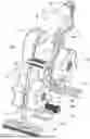
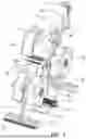
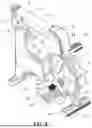
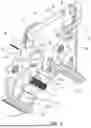
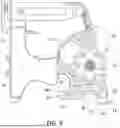
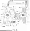
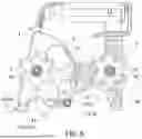
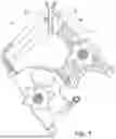
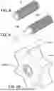
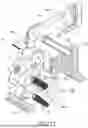
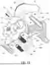
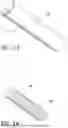
Sources:
- United States Patent and Trademark Office - verify current appl. status at the USPTO↗
Recent applications in this class:
- » 20260125235 2026-05-07
MAGNETIC TAPE DISPENSER - » 20260109565 2026-04-23
APPLICATION DEVICE FOR THE APPLICATION OF WEB-SHAPED ADHESIVE ELEMENTS - » 20250368466 2025-12-04
HANDHELD TAPE DISPENSER AND METHODS OF USE THEREOF - » 20250326599 2025-10-23
DUAL ROLLER APPLICATOR FOR SEAM TAPE - » 20250206558 2025-06-26
TAPE APPLICATOR - » 20250197154 2025-06-19
HEAD FOR TAPING DEVICE - » 20250115451 2025-04-10
TAPE CUTTER - » 20250019198 2025-01-16
TAPE CUTTER - » 20240208763 2024-06-27
Surface Characterization Module and System Including Same - » 20240199365 2024-06-20
TAPE APPLICATOR AND METHOD OF USING