WASHING MACHINE AND CONTROLLING METHOD THEREOF
US20260185281A1
2026-07-02
19/381,410
2025-11-06
Smart Summary: A washing machine has a smart system that helps it operate more efficiently. It uses sensors to gather information about water levels and movement during washing cycles. When the water level gets too high, the machine knows to drain some water. It also adjusts its washing process based on how fast the drum is spinning. This technology helps ensure that clothes are cleaned properly while managing water usage effectively. 🚀 TL;DR
Abstract:
Provided is a washing machine including: a memory storing instructions; at least one processor including processing circuitry; a drive device configured to drive the washing machine using a motor; a water supply device configured to supply water into the washing machine; a drain device configured to discharge water from the washing machine; and a sensor device, wherein, at least one processor, individually or collectively, is configured to execute the instructions and to cause the washing machine to: perform a water supply cycle in response to a command being received, obtain acceleration data and water level data from the sensor device, obtain a first acceleration from the sensor device based on a specified event related to the motor occurring, obtain a second acceleration in response to a current water level of the washing machine exceeding a threshold water level, perform a first draining cycle in response to the second acceleration exceeding a threshold acceleration, obtain a third acceleration in response to a wash cycle starting after the first draining cycle, and perform a second draining cycle based on a difference between the first acceleration and the third acceleration.
Inventors:
- Taehyung KIM 41 🇰🇷 Suwon-si, South Korea
- Jonghun SUNG 17 🇰🇷 Suwon-si, South Korea
- Sungjong KIM 18 🇰🇷 Suwon-si, South Korea
- Sooyeon JIN 4 🇰🇷 Suwon-si, South Korea
- Haneal LEE 7 🇰🇷 Suwon-si, South Korea
Applicant:
Interested in similar patents?
Get notified when new applications in this technology area are published.
Classification:
D06F33/48 » CPC main
Control of operations performed in washing machines or washer-dryers ; Control of washing machines characterised by the purpose or target of the control Preventing or reducing imbalance or noise
D06F23/04 » CPC further
Washing machines with receptacles, e.g. perforated, having a rotary movement, e.g. oscillatory movement, the receptacle serving both for washing and for centrifugally separating water from the laundry and rotating or oscillating about a vertical axis
D06F33/34 » CPC further
Control of operations performed in washing machines or washer-dryers ; Control of washing machines characterised by the purpose or target of the control ; Control of operational steps, e.g. optimisation or improvement of operational steps depending on the condition of the laundry of water filling
D06F33/36 » CPC further
Control of operations performed in washing machines or washer-dryers ; Control of washing machines characterised by the purpose or target of the control ; Control of operational steps, e.g. optimisation or improvement of operational steps depending on the condition of the laundry of washing
D06F33/42 » CPC further
Control of operations performed in washing machines or washer-dryers ; Control of washing machines characterised by the purpose or target of the control ; Control of operational steps, e.g. optimisation or improvement of operational steps depending on the condition of the laundry of draining
D06F34/16 » CPC further
Details of control systems for washing machines, washer-dryers or laundry dryers; Arrangements for detecting or measuring specific parameters Imbalance
D06F34/32 » CPC further
Details of control systems for washing machines, washer-dryers or laundry dryers; Arrangements for program selection, e.g. control panels therefor; Arrangements for indicating program parameters, e.g. the selected program or its progress characterised by graphical features, e.g. touchscreens
D06F37/304 » CPC further
Details specific to washing machines covered by groups -; Driving arrangements Arrangements or adaptations of electric motors
D06F39/083 » CPC further
Details of washing machines not specific to a single type of machines covered by groups - ; Liquid supply or discharge arrangements Liquid discharge or recirculation arrangements
D06F39/087 » CPC further
Details of washing machines not specific to a single type of machines covered by groups - ; Liquid supply or discharge arrangements Water level measuring or regulating devices
D06F39/088 » CPC further
Details of washing machines not specific to a single type of machines covered by groups - ; Liquid supply or discharge arrangements Liquid supply arrangements
D06F2103/18 » CPC further
Parameters monitored or detected for the control of domestic laundry washing machines, washer-dryers or laundry dryers Washing liquid level
D06F2103/24 » CPC further
Parameters monitored or detected for the control of domestic laundry washing machines, washer-dryers or laundry dryers Spin speed; Drum movements
D06F2103/26 » CPC further
Parameters monitored or detected for the control of domestic laundry washing machines, washer-dryers or laundry dryers Unbalance; Noise level
D06F2103/46 » CPC further
Parameters monitored or detected for the control of domestic laundry washing machines, washer-dryers or laundry dryers; Current or voltage of the motor driving the drum
D06F2105/02 » CPC further
Systems or parameters controlled or affected by the control systems of washing machines, washer-dryers or laundry dryers Water supply
D06F2105/08 » CPC further
Systems or parameters controlled or affected by the control systems of washing machines, washer-dryers or laundry dryers Draining of washing liquids
D06F2105/60 » CPC further
Systems or parameters controlled or affected by the control systems of washing machines, washer-dryers or laundry dryers; Indications or alarms to the control system or to the user Audible signals
D06F37/30 IPC
Details specific to washing machines covered by groups - Driving arrangements
D06F39/08 IPC
Details of washing machines not specific to a single type of machines covered by groups - Liquid supply or discharge arrangements
Description
CROSS-REFERENCE TO RELATED APPLICATIONS
This application is a bypass continuation of International Application No. PCT/KR2025/015929, filed on Oct. 9, 2025, which is based on and claims priority to Korean Patent Application No. 10-2024-0200725, filed on Dec. 30, 2024, in the Korean Intellectual Property Office, the disclosures of which are incorporated by reference herein in their entireties.
BACKGROUND
1. Field
The disclosure relates to a washing machine and a controlling method thereof, and for example, to a washing machine having reduced vibration and a controlling method thereof.
2. Description of Related Art
A washing machine inevitably vibrates as a motor rotates. If the washing machine is unbalanced, significant vibration may occur in the washing machine as the motor rotates. Such vibration may result in noise.
Various methods may be provided to reduce vibration in the washing machine. Examples of the methods may include reducing power supply to reduce a motor rotation speed or providing a user with a warning notification. However, reducing a motor rotation speed may result in an issue of reduced washing performance. Even in case of providing the user with the warning notification, the user is still required to independently resolve the issue.
A water supply cycle for supplying water to the washing machine is essential for a wash function. A load on the washing machine may be increased as more water supplied thereto. The increased load may result in increased vibration or noise that did not occur before.
SUMMARY
Embodiments of the disclosure provide a washing machine that uses acceleration data and water level data for a wash function, thereby performing a draining cycle if vibration occurs, and a controlling method thereof.
According to an example embodiment of the present disclosure, provided is a washing machine including: a memory storing instructions; at least one processor including processing circuitry; a drive device comprising a motor configured to drive the washing machine; a water supply device configured to supply water into the washing machine; a drain device comprising a drain configured to discharge water from the washing machine; and a sensor device comprising at least one sensor, wherein, at least one processor individually or collectively is configured to execute the instructions and to cause the washing machine to: perform a water supply cycle based on receiving a command for washing, obtain acceleration data and water level data from the sensor device, obtain a first acceleration from the sensor device based on a specified event related to the motor occurring, obtain a second acceleration based on a current water level of the washing machine exceeding a threshold water level, perform a first draining cycle based on the second acceleration exceeding a threshold acceleration, obtain a third acceleration based on a wash cycle starting after the water supply cycle, and perform a second draining cycle based on a difference between the first acceleration and the third acceleration.
The predetermined (e.g., specified) event may include an event in which a motor rotation rate is greater than or equal to a threshold rotation rate.
At least one processor, individually or collectively, may be configured to cause the washing machine to: obtain the threshold acceleration by adding a reference value to the second acceleration, identify a vibration event as occurring based on the second acceleration exceeding the threshold acceleration, and perform the first draining cycle to reduce the water level based on a first level based on the vibration event being identified during the water supply cycle.
At least one processor, individually or collectively may be configured to cause the washing machine to: obtain the first acceleration having a maximum value during a first threshold time based on the specified event occurring, obtain the second acceleration having a maximum value during a second threshold time based on the current water level exceeding the threshold water level, obtain the third acceleration having a maximum value during a third threshold time based on the wash cycle starting, and perform the second draining cycle based on the first acceleration and the third acceleration.
At least one processor, individually or collectively, may be configured to cause the washing machine to: obtain a first difference value by subtracting the first acceleration from the third acceleration, identify the vibration event as occurring based on the first difference value exceeding a first threshold value, and perform the second draining cycle to reduce the water level based on a second level based on the vibration event being identified during the wash cycle.
At least one processor, individually or collectively, may be configured to cause the washing machine to: obtain current data from the sensor device, obtain the first acceleration and a first current, each having a maximum value, during the first threshold time based on the specified event occurring, obtain the third acceleration and a second current, each having a maximum value, during the third threshold time based on the wash cycle starting, and perform the second draining cycle based on the first acceleration, the third acceleration, the first current, or the second current.
At least one processor, individually or collectively, may be configured to cause the washing machine to: obtain a second difference value by subtracting the first current from the second current, identify the vibration event as occurring based on the first difference value exceeding the first threshold value and the second difference value exceeding a second threshold value, and perform the second draining cycle to reduce the water level based on the second level based on the vibration event being identified during the wash cycle.
At least one processor, individually or collectively, may be configured to cause the washing machine to: provide a guidance user interface (UI) indicating the vibration event if the vibration event is identified.
The washing machine may include a speaker, wherein, at least one processor, individually or collectively, may be configured to cause the washing machine to provide the guidance UI including an audio signal for notifying the vibration event through the speaker.
The washing machine may include a display, wherein, at least one processor, individually or collectively, may be configured to cause the washing machine to provide the guidance UI including an image signal for notifying the vibration event on the display.
According to an example embodiment of the present disclosure, provided is a method of controlling a washing machine, the method including: performing a water supply cycle based on receiving a command for washing; obtaining acceleration data and water level data; obtaining a first acceleration based on a specified event related to a motor occurring; obtaining a second acceleration based on a current water level of the washing machine exceeding a threshold water level; performing a first draining cycle based on the second acceleration exceeding a threshold acceleration; obtaining a third acceleration based on a wash cycle starting after the water supply cycle; and performing a second draining cycle based on a difference between the first acceleration and the third acceleration.
The specified event may include an event in which a motor rotation rate is greater than or equal to a threshold rotation rate.
The method may include: obtaining the threshold acceleration by adding a reference value to the second acceleration, wherein in the performing of the first draining cycle, a vibration event is identified as occurring based on the second acceleration exceeding the threshold acceleration, and the first draining cycle is performed to reduce the water level based on a first level based on the vibration event being identified during the water supply cycle.
In the obtaining of the first acceleration, the first acceleration having a maximum value may be obtained during a first threshold time based on the specified event occurring, in the obtaining of the second acceleration, the second acceleration having a maximum value may be obtained during a second threshold time based on the current water level exceeding the threshold water level, in the obtaining of the third acceleration, the third acceleration having a maximum value may be obtained during a third threshold time based on the wash cycle starting, and in the performing of the second draining cycle, the second draining cycle may be performed based on the first acceleration and the third acceleration.
In the performing of the second draining cycle, a first difference value may be obtained by subtracting the first acceleration from the third acceleration. The vibration event may be identified as occurring based on the first difference value exceeding a first threshold value, and the second draining cycle may be performed to reduce the water level based on a second level based on the vibration event being identified during the wash cycle.
The method may include: obtaining current data; obtaining the first acceleration and a first current, each having a maximum value, during the first threshold time based on the specified event occurring; obtaining the third acceleration and a second current, each having a maximum value, during the third threshold time based on the wash cycle starting; and performing the second draining cycle based on the first acceleration, the third acceleration, the first current, or the second current.
In the performing of the second draining cycle, a second difference value may be obtained by subtracting the first current from the second current. The vibration event may be identified as occurring based on the first difference value exceeding the first threshold value and the second difference value exceeding a second threshold value. The second draining cycle may be performed to reduce the water level based on the second level based on the vibration event being identified during the wash cycle.
The method may include providing a guidance user interface (UI) indicating the vibration event based on the vibration event being identified.
In the providing of the guidance UI, the guidance UI including an audio signal for notifying the vibration event may be provided.
In the providing of the guidance UI, the guidance UI including an image signal for notifying the vibration event may be provided.
BRIEF DESCRIPTION OF THE DRAWINGS
The above and other aspects, features and advantages of certain embodiments of the present disclosure will be more apparent from the following detailed description, taken in conjunction with the accompanying drawings, in which:
FIG. 1 is a perspective view illustrating an example washing machine according to various embodiments;
FIG. 2 is a block diagram illustrating an example configuration of the washing machine according to various embodiments;
FIG. 3 is a block diagram illustrating an example configuration of the washing machine shown in FIG. 2 according to various embodiments;
FIG. 4 is a diagram illustrating an acceleration sensor included in the washing machine according to various embodiments;
FIG. 5 is a flowchart illustrating an example operation for identifying a lower obstacle according to various embodiments;
FIG. 6 is a flowchart illustrating an example operation for performing a draining cycle if the lower obstacle is identified according to various embodiments;
FIG. 7 is a flowchart illustrating an example operation for identifying the lower obstacle during a water supply cycle according to various embodiments;
FIG. 8 is a flowchart illustrating an example operation for identifying the lower obstacle during a wash cycle according to various embodiments;
FIG. 9 is a flowchart illustrating an example operation for identifying the lower obstacle based on an acceleration difference according to various embodiments;
FIG. 10 includes graphs illustrating examples in which the lower obstacle is identified according to various embodiments;
FIG. 11 is a diagram for illustrating example water level change in a case where the lower obstacle is identified during the water supply cycle according to various embodiments;
FIG. 12 includes graphs illustrating examples in which the lower obstacle is identified during the water supply cycle according to various embodiments;
FIG. 13 is a diagram illustrating example water level change in a case where the lower obstacle is identified during the water supply cycle or the wash cycle according to various embodiments;
FIG. 14 includes graphs illustrating examples in which the lower obstacle is identified during the water supply cycle or the wash cycle according to various embodiments;
FIG. 15 is a diagram illustrating example water level change in a case where the lower obstacle is identified during the wash cycle according to various embodiments;
FIG. 16 includes graphs illustrating examples in which the lower obstacle is identified during the wash cycle according to various embodiments;
FIG. 17 is a flowchart illustrating an example operation for stopping a current cycle being performed based on acceleration according to various embodiments;
FIG. 18 is a flowchart illustrating an example operation for stopping the current cycle being performed based on a water level according to various embodiments;
FIG. 19 is a diagram illustrating an example operation for outputting a guidance through the washing machine according to various embodiments;
FIG. 20 is a diagram illustrating an example system including the washing machine, a server, and a terminal device according to various embodiments;
FIG. 21 is a diagram illustrating an example guidance user interface (UI) displayed on a display according to various embodiments;
FIG. 22 is a diagram illustrating an example guidance UI displayed on the display according to various embodiments;
FIG. 23 includes graphs illustrating example acceleration difference and current difference according to various embodiments;
FIG. 24 is a flowchart illustrating an example operation for identifying the lower obstacle during the water supply cycle according to various embodiments;
FIG. 25 is a flowchart illustrating an example operation for identifying the lower obstacle during the wash cycle according to various embodiments; and
FIG. 26 is a flowchart illustrating an example method of a washing machine according to various embodiments.
DETAILED DESCRIPTION
It should be understood that various embodiments of the present disclosure and terms used herein are not intended to limit technical features described in the present disclosure, and rather are intended to include various modifications, equivalents, and substitutions.
Throughout the accompanying drawings, similar components are denoted by similar reference numerals.
A singular noun corresponding to an item is intended to include one or more of the items unless a relevant context clearly indicates otherwise.
In the present disclosure, an expression such as “A or B”, “at least one of A and B”, “at least one of A or B”, “A, B, or C”, “at least one of A, B, and C”, “at least one of A, B, or C”, or the like may include any one of the items listed together or all possible combinations thereof.
A term “and/or” includes a combination of a plurality of related items or any one of the plurality of related items.
Terms such as “first”, “second”, or the like may be used simply to distinguish one element and another element from each other, and do not limit the corresponding components in any other respect (e.g., importance or order).
If a component (for example, a first component) is mentioned to be “coupled with/to” or “connected to” another component (for example, a second component) with or without terms “operatively or communicatively”, it should be understood that the component may be directly coupled to another component (e.g., in a wired manner), in a wireless manner, or through a third component).
It should be further understood that terms “include”, “have” or the like, used in the disclosure specify the presence of features, numerals, steps, operations, components, parts mentioned in the disclosure or combinations thereof, and do not preclude the presence or addition of one or more other features, numerals, steps, operations, components, parts, or combinations thereof.
If a component is referred to as being “connected”, “coupled”, “supported”, or “in contact” with another component, it includes not only a case where the components are directly connected, coupled, supported, or in contact with each other, but also a case where the components are indirectly connected, coupled, supported, or in contact with each other through a third component.
If a component is referred to be disposed “on” another component, it includes not only a case where the component is in contact with another component, but also a case where still another component is interposed between the two components.
A washing machine according to various embodiments may perform wash, rinse, dehydration, and dry cycles. The washing machine is an example of a clothing treatment device, which is a concept encompassing a device that washes clothing (laundry items or drying items), a device that dries clothing, and a device that may perform both washing and drying of clothing.
The washing machine according to the various embodiments may include a top-loading washing machine in which a laundry inlet for loading or withdrawing laundry is disposed to face upward or a front-loading washing machine in which the laundry inlet is disposed to face forward. The washing machine according to the various embodiments may include a washing machine adopting a loading method other than the top-loading washing machine or the front-loading washing machine.
The top-loading washing machine may wash laundry using a water flow generated by a rotating body such as a pulsator. The front-loading washing machine may wash laundry by rotating a drum and repeatedly lifting and lowering laundry. The front-loading washing machine may include a washing machine having a dryer function that may dry laundry accommodated in the drum. The washing machine having a dryer function may include a hot air supply device for supplying high-temperature air into the drum and a condensing device for removing moisture from air discharged from the drum. For example, the washing machine having a dryer function may include a heat pump device. The washing machine according to the various embodiments may include a washing machine having a washing method other than the above-described washing methods.
The washing machine according to various embodiments may include a housing that accommodates various components therein. The housing may be provided as a box having the laundry inlet disposed on one side.
The washing machine may include a door for opening and closing the laundry inlet. The door may be rotatably mounted to the housing using a hinge. At least a portion of the door may be transparent or translucent to allow an interior of the housing to be seen.
The washing machine may include a tub disposed within the housing to store water. The tub may have a substantially cylindrical shape having a tub opening disposed on one side thereof, and the tub opening may be disposed within the housing to correspond to the laundry inlet.
The tub may be connected to the housing using a damper. The damper may absorb vibration occurring while the drum rotates, thereby reducing vibration transmitted to the housing.
The washing machine may include the drum disposed to accommodate laundry therein.
The drum may be disposed within the tub to have a drum opening disposed on one side thereof to correspond to the laundry inlet and the tub opening. Laundry may be accommodated within the drum or withdrawn from the drum by sequentially passing through the laundry inlet, the tub opening, and the drum opening.
The drum may perform each operation of the wash, rinse, and/or dehydration cycle while rotating within the tub. A cylindrical wall of the drum may include a number of perforations, thus allowing water stored in the tub to flow into or out of the drum.
The washing machine may include a drive device for rotating the drum. The drive device may include a drive motor and a rotating shaft for transmitting a driving force generated by the drive motor to the drum. The rotating shaft may pass through the tub and be connected to the drum.
The drive device may rotate the drum forward or backward to cause the washing machine to perform each operation of the wash, rinse, and/or dehydration, or dry cycle.
The washing machine may include a water supply device for supplying water to the tub. The water supply device may include a water supply pipe and a water supply valve disposed on the water supply pipe. The water supply pipe may be connected to an external water supply source. The water supply pipe may extend from the external water supply source to a detergent supply device and/or the tub. Water may be supplied to the tub through the detergent supply device. Water may be supplied to the tub without passing through the detergent supply device.
The water supply valve may open or close the water supply pipe in response to an electrical signal from a control device. The water supply valve may allow or block supply of water from the external water supply source to the tub. For example, the water supply valve may include a solenoid valve that opens and closes in response to the electrical signal.
The washing machine may include a detergent supply device for supplying detergent to the tub. The detergent supply device may include a manual detergent supply device that requires a user to load detergent for each wash cycle, and an automatic detergent supply device that stores a large amount of detergent and automatically loads a predetermined amount of detergent while performing washing. The detergent supply device may include a detergent box for storing detergent. The detergent supply device may supply detergent into the tub during a water supply process. Water supplied through the water supply pipe may be mixed with detergent through the detergent supply device. Water mixed with detergent may be supplied into the tub. Detergent is used as a comprehensive term for pre-wash detergent, main wash detergent, fabric softener, bleach, or the like, and the detergent box may be partitioned into a pre-wash detergent storage region, a main wash detergent storage region, a fabric softener storage region, and a bleach storage region.
The washing machine may include a drain device for discharging water accommodated in the tub to the outside. The drain device may include a drain pipe extending from the bottom of the tub to the outside of the housing, a drain valve disposed on the drain pipe to open and close the drain pipe, and a pump disposed on the drain pipe. The pump may pump water in the drain pipe to the outside of the housing.
The washing machine may include a control panel disposed on one side of the housing. The control panel may provide a user interface for the user to interact with the washing machine. The user interface may include at least one input interface and at least one output interface.
At least one input interface may convert sensory information received from the user into the electrical signal.
At least one input interface may include a power button, an operation button, a course selection dial (or a course selection button), or a wash, rinse, or dehydration setting button. For example, at least one input interface may include a tact switch, a push switch, a slide switch, a toggle switch, a micro switch, a touch switch, a touch pad, a touchscreen, a jog dial, and/or a microphone.
At least one output interface may visually or audibly transmit information related to an operation of the washing machine to the user.
For example, at least one output interface may transmit, to the user, information related to a wash course, an operation time of the washing machine, or a setting for wash, rinse, or dehydration. The information related to the washing machine operation may be output via a screen, an indicator, a voice, or the like. At least one output interface may include, for example, a liquid crystal display (LCD) panel, a light emitting diode (LED) panel, or a speaker.
The washing machine may include a communication module including various communication circuitry for communicating with an external device in a wired and/or wireless manner.
The communication module may include at least one of a short-range communication module or a long-range communication module.
The communication module may transmit data to the external device (e.g., a server, a user device, and/or a home appliance) or receive data from the external device. For example, the communication module may establish communication with the server, the user device, and/or the home appliance, and transmit and receive various data.
To this end, the communication module may support the establishment of a direct (e.g., wired) communication channel or a wireless communication channel between the external devices, and performing the communication through the established communication channel. According to an embodiment, the communication module may include the wireless communication module (e.g., a cellular communication module, a short-range wireless communication module, or a global navigation satellite system (GNSS) communication module) or the wired communication module (e.g., a local area network (LAN) communication module or a powerline communication module). A corresponding communication module among these communication modules may communicate with the external device via a first network (e.g., a short-range communication network such as Bluetooth, wireless fidelity (Wi-Fi) direct, or infrared data association (IrDA)) or a second network (e.g., a long-range communication network such as a legacy cellular network, a fifth generation (5G) network, a next-generation communication network, the Internet, or a computer network (e.g., the LAN or a wide area network (WAN)). These various types of communication modules may be integrated into a single component (e.g., a single chip) or implemented as a plurality of separate components (e.g., multiple chips).
The short-range wireless communication module may include a Bluetooth communication module, a Bluetooth low energy (BLE) communication module, a near-field communication module, a wireless local area network (WLAN) communication module (e.g., Wi-Fi), a Zigbee communication module, an infrared communication module (e.g., an infrared data association (IrDA) communication module), a Wi-Fi Direct (WFD) communication module, an ultrawideband (UWB) communication module, an Ant+ communication module, a microwave (uWave) communication module, or the like, and is not limited thereto.
The long-range communication module may include a communication module that performs various types of long-range communication, and may include a mobile communication device. The mobile communication device may transmit and receive a wireless signal with at least one of a base station, an external terminal, or the server via a mobile communication network.
In an embodiment, the communication module may communicate with the external device such as the server, the user device, or another home appliance through a nearby access point (AP). The access point (AP) may connect the local area network (LAN) to which the washing machine or the user device is connected to the wide area network (WAN) to which the server is connected. The washing machine or the user device may be connected to the server via the wide area network (WAN). The control device may control various components included in the washing machine (e.g., the drive motor or the water supply valve). The control device may control the various components included in the washing machine to perform at least one cycle including water supply, wash, rinse, and/or dehydration, based on a user input. For example, the control device may control the drive motor to adjust a drum rotation speed, or control the water supply valve of the water supply device to supply water to the tub.
The control device may include a hardware module such as a central processing unit (CPU) and/or a memory, and a software module such as a control program. For example, the control device may include an algorithm used for controlling operations of the components included in the washing machine, at least one memory storing program-type data, and at least one processor, including various processing circuitry, performing the aforementioned operation using data stored in at least one memory. The memory and the processor may each be implemented as separate chips. The processor may include one or more processor chips or one or more processing cores. The memory may include one or more memory chips or one or more memory blocks. The processor may be implemented as a single chip.
Hereinafter, the washing machine according to various example embodiments is described in greater detail with reference to the accompanying drawings.
FIG. 1 is a perspective view illustrating an example washing machine 100 according to various embodiments.
Referring to FIG. 1, the washing machine 100 may be disposed on a water tray 10. The water tray 10 may be referred to as a water drip pan. The water tray 10 may prevent/reduce or retain water drained from the washing machine 100 from flowing out of the water tray 10.
The washing machine 100 and the water tray 10 may come into contact each other. For example, the water tray 10 may not come into contact before the washing machine 100 starts a water supply cycle. If the washing machine 100 starts the water supply cycle, a weight of a washing tub included in the washing machine 100 may increase as water is supplied to the tub. As the weight of the tub increases, a load on the washing machine 100 may be applied in a direction of gravity (downward). As the load on the washing machine 100 is applied in the direction of gravity due to the water supply, the washing machine 100 may come into contact with the water tray 10.
If the washing machine 100 and the water tray 10 come into contact with each other, noise may occur due to a motor rotation. The reason is that friction occurs while the motor of the washing machine and the water tray are bound to each other by the gravity applied to the tub of the washing machine.
The washing machine 100 may perform a draining cycle to adjust balance. A time point for performing the draining cycle may vary. If a lower obstacle is identified during the water supply cycle or the wash cycle, the washing machine 100 may perform the draining cycle.
Hereinafter, an example operation for identifying the lower obstacle is described in greater detail. According to various embodiments, the washing machine 100 may identify various events that upset the balance or cause friction in the washing machine 100, other than the lower obstacle. The lower obstacle described below may be replaced with an event that changes balance or causes friction in the washing machine 100.
The washing machine 100 may identify a vibration event. The vibration event may include at least one of an event in which the washing machine 100 comes into contact with an obstacle, an event in which an obstacle is identified at a lower portion of the washing machine 100, an event in which the washing machine 100 loses balance, an event in which a strong restraining force is applied to the washing machine 100, or an event in which the washing machine 100 moves beyond a threshold acceleration.
FIG. 2 is a block diagram illustrating an example configuration the washing machine 100 according various embodiments.
Referring to FIG. 2, the washing machine 100 may include at least one of a memory 140 storing instructions, at least one processor 130 including processing circuitry, a drive device (e.g., including a motor) 170 for driving the washing machine 100 using the motor, a water supply device (e.g., including a pipe and/or a valve) 182 for supplying water into the washing machine 100, a drain device (e.g., including a drain) 183 for discharging water from the washing machine 100, and/or a sensor device (e.g., including at least one sensor) 190.
The sensor device 190 may include at least one of an acceleration sensor 191, a current sensor 192, or a water level sensor 193.
The acceleration sensor 191 may obtain acceleration data representing a movement of the washing machine 100. For example, the acceleration sensor 191 may be implemented as a micro-electro-mechanical system (MEMS). The acceleration sensor 191 may obtain the acceleration data representing the vibration, imbalance, rotation speed, or the like of the washing machine 100. The washing machine 100 may use a position sensor or a distance sensor instead of the acceleration sensor 191.
The current sensor 192 may be a sensor that measures a supply current supplied to the motor. For example, the current sensor 192 may include a sensor that detects a Q-axis current (Iq) supplied to the motor. The Q-axis current may be a current that generates a motor torque. The Q-axis current may be a current that flows in an axis perpendicular to a rotational direction. The larger the Q-axis current, the greater the motor torque.
A relationship between magnets and currents inside the motor may be expressed in a DQ coordinate system. A D-axis current may be a current that adjusts a magnitude of the magnetic flux, and the Q-axis current may be the current that generates the torque. The D-axis current may be a current that flows in the same direction as the magnets (or a rotor) inside the motor. The Q-axis current may be a current that crosses the magnets (or the rotor) inside the motor at a right angle.
The water level sensor 193 may detect a water level of water supplied into the washing machine 100. The water level sensor 193 may obtain water level data indicating the water level of water supplied into a water tub included in the washing machine 100. For example, the water level sensor 193 may obtain the water level data indicating a water level frequency.
The at least one processor 130, as described above, may include various processing circuitry and/or multiple processors. For example, as used herein, including the claims, the term “processor” may include various processing circuitry, including at least one processor, wherein one or more of at least one processor, individually and/or collectively in a distributed manner, may be configured to perform various functions described herein. As used herein, when “a processor”, “at least one processor”, and “one or more processors” are described as being configured to perform numerous functions, these terms cover situations, for example and without limitation, in which one processor performs some of recited functions and another processor(s) performs other of recited functions, and also situations in which a single processor may perform all recited functions. Additionally, the at least one processor may include a combination of processors performing various of the recited/disclosed functions, e.g., in a distributed manner. At least one processor may execute program instructions to achieve or perform various functions.
At least one processor 130 may receive a user command for washing. For example, the user command may be obtained through a manipulation interface included in the washing machine 100. For example, the user command may be obtained through a microphone included in the washing machine 100.
The user command for washing may be a command to perform the water supply cycle and the wash cycle.
At least one processor 130 may perform the water supply cycle if the user command for washing is obtained. At least one processor 130 may obtain the acceleration data and the water level data from the sensor device 190. At least one processor 130 may obtain the acceleration data from the acceleration sensor 191. At least one processor 130 may obtain the water level data from the water level sensor 193.
If the water supply cycle starts, at least one processor 130 may identify whether a predetermined event related to the motor occurs. The motor may be included in the drive device 170. The motor may generate a rotational force to drive the washing machine 100.
For example, the predetermined event related to the motor may include an event in which the motor rotation rate is greater than or equal to a threshold rotation rate. At least one processor 130 may identify the motor rotation rate in real time. At least one processor 130 may identify that the predetermined event occurs if the motor rotation rate is greater than or equal to the threshold rotation rate. The predetermined event may be described as a rotation event, a spin event, a torque event, a motion event, a drive event, a motor event, or the like.
For example, the event related to the motor may include an event in which the supply current supplied to the motor is greater than or equal to a threshold current.
At least one processor 130 may obtain a first acceleration from the sensor device 190 if the predetermined event related to the motor occurs.
At least one processor 130 may identify a current water level of the washing machine 100 in real time based on the water level data. At least one processor 130 may identify whether the current water level exceeds a threshold water level during the water supply cycle.
At least one processor 130 may obtain a second acceleration if the current water level of the washing machine 100 exceeds the threshold water level during the water supply cycle.
At least one processor 130 may compare the second acceleration with the threshold acceleration to determine whether to perform a first draining cycle.
At least one processor 130 may perform the first draining cycle if the second acceleration exceeds the threshold acceleration. The first draining cycle may refer to a draining cycle performed during the water supply cycle.
At least one processor 130 may identify whether the wash cycle starts after the first draining cycle is performed.
At least one processor 130 may obtain a third acceleration if the wash cycle starts after the water supply cycle (or the first draining cycle). At least one processor 130 may perform a second draining cycle based on a difference between the first acceleration and the third acceleration. At least one processor 130 may determine whether to perform the second draining cycle by comparing the first acceleration with the third acceleration. If the predetermined event related to the motor does not occur, at least one processor 130 may be perform the second draining cycle based on the third acceleration.
The first acceleration may be a value detected during the water supply cycle, and the third acceleration may be a value detected during the wash cycle. At least one processor 130 may determine whether to perform the second draining cycle during the wash cycle based on an acceleration difference between the water supply cycle and the wash cycle. The greater the vibration occurring in the washing machine 100, the greater the acceleration difference may be.
At least one processor 130 may obtain the threshold acceleration by adding a reference value to the second acceleration. The threshold acceleration may be determined based on the detected acceleration data. If the current water level exceeds the threshold water level, at least one processor 130 may obtain the threshold acceleration by adding the reference value to the second acceleration. The threshold acceleration may vary depending on the water level.
At least one processor 130 may identify whether the vibration event occurs by comparing the second acceleration with the threshold acceleration. The vibration event may refer to an event in which the washing machine 100 vibrates abnormally. The vibration event may indicate an event in which acceleration of the washing machine 100 is greater than or equal to the threshold acceleration.
For example, the vibration event may occur if an obstacle is identified at the lower portion of the washing machine 100. The lower portion of the washing machine 100 may include an assembly tub.
For example, as the water level of the washing machine 100 increases, the lower portion of the washing machine 100 may come into contact with an object other than the washing machine 100. If the washing machine 100 comes into contact with another object, the vibration event may occur due to the motor rotation.
At least one processor 130 may identify the vibration event as occurring if the second acceleration exceeds the threshold acceleration. At least one processor 130 may perform the first draining cycle to reduce the water level based on a first level if the vibration event is identified during the water supply cycle. The first level may indicate at least one of a water level for drainage or a water amount for drainage. The first level is described in greater detail below with reference to FIGS. 11 and 12.
At least one processor 130 may obtain current data from the sensor device 190. At least one processor 130 may obtain the current data from the current sensor 192.
At least one processor 130 may obtain the first acceleration having a maximum value during a first threshold time if the predetermined event related to the motor occurs. At least one processor 130 may obtain a first acceleration data group including a plurality of acceleration values during the first threshold time starting from a time point at which the predetermined event occurs. At least one processor 130 may obtain the first acceleration indicating the maximum value among the plurality of acceleration values.
According to an embodiment, at least one processor 130 may obtain the first acceleration based on an average or median value instead of the maximum value. The maximum value may be described as a representative value.
At least one processor 130 may obtain the first acceleration, and then compare the current water level with the threshold water level in real time based on the water level data.
At least one processor 130 may obtain the second acceleration having a maximum value during a second threshold time if the current water level exceeds the threshold water level.
At least one processor 130 may obtain a second acceleration data group including a plurality of acceleration values during the second threshold time starting from a time point at which the current water level exceeds the threshold water level. At least one processor 130 may obtain the second acceleration indicating the maximum value among the plurality of acceleration values.
According to an embodiment, at least one processor 130 may obtain the second acceleration based on the average or median value instead of the maximum value. The maximum value may be described as the representative value.
If the second acceleration is obtained, at least one processor 130 may obtain the threshold acceleration by adding the reference value to the second acceleration. At least one processor 130 may compare a current acceleration with the threshold acceleration to determine whether to perform the first draining cycle. If the current acceleration exceeds the threshold acceleration, at least one processor 130 may perform the first draining cycle.
At least one processor 130 may perform the water supply cycle. If the water supply cycle is completed, at least one processor 130 may perform the wash cycle.
At least one processor 130 may obtain the third acceleration having a maximum value during a third threshold time if the wash cycle starts. At least one processor 130 may obtain a third acceleration data group including a plurality of acceleration values during the third threshold time starting from a time point at which the wash cycle starts. At least one processor 130 may obtain the third acceleration indicating the maximum value among the plurality of acceleration values.
According to an embodiment, at least one processor 130 may obtain the third acceleration based on the average or median value instead of the maximum value. The maximum value may be described as the representative value.
At least one processor 130 may perform the second draining cycle based on the first acceleration and the third acceleration. At least one processor 130 may compare the first acceleration with the third acceleration to determine whether to perform the second draining cycle.
At least one processor 130 may obtain a first difference value by subtracting the first acceleration from the third acceleration.
At least one processor 130 may identify the vibration event as occurring if the first difference value exceeds a first threshold value. At least one processor 130 may perform the second draining cycle to reduce the water level based on a second level if the vibration event is identified during the wash cycle. The second level may indicate at least one of the water level for drainage or the water amount for drainage. The second level is described in greater detail below with reference to FIGS. 13 to 16. The first level and the second level may be different.
If the first acceleration is not yet determined due to the predetermined event related to the motor not occurring, At least one processor 130 may perform the second draining cycle based on the third acceleration. At least one processor 130 may compare the third acceleration with a second threshold acceleration to determine whether to perform the second draining cycle.
If the third acceleration exceeds the second threshold acceleration, at least one processor 130 may identify that the vibration event occurs. If the vibration event is identified during the wash cycle, at least one processor 130 may perform the second draining cycle to reduce the water level based on the second level. The second level may indicate at least one of the water level for drainage or the water amount for drainage. The second level is described in greater detail below with reference to FIGS. 13 to 16. The first level and the second level may be different.
The above-described operation describes an embodiment of comparing the respective accelerations detected during the water supply cycle and the wash cycle to determine whether the second draining cycle is performed. Further details thereof are described in greater detail below with reference to FIG. 9.
According to an embodiment, the washing machine 100 may determine whether to perform the second draining cycle by comparing each acceleration with each current detected during the water supply cycle and the wash cycle. A description of the acceleration may overlap with the description provided above. A redundant description thereof may not be repeated here.
At least one processor 130 may obtain current data from the sensor device 190. At least one processor 130 may obtain current data through the current sensor 192. If the water supply cycle starts, at least one processor 130 may obtain current data from the current sensor 192.
At least one processor 130 may obtain the first acceleration and a first current, each having a maximum value, during the first threshold time if the predetermined event related to the motor occurs.
At least one processor 130 may obtain a first current data group including a plurality of current values during the first threshold time starting from the time point at which the predetermined event occurs. At least one processor 130 may obtain the first current indicating the maximum value among the plurality of current values.
According to an embodiment, at least one processor 130 may obtain the first current based on the average or median value instead of the maximum value. The maximum value may be described as the representative value.
At least one processor 130 may obtain the third acceleration and a second current, each having a maximum value, during the third threshold time if the wash cycle starts.
At least one processor 130 may obtain a second current data group including a plurality of current values during the third threshold time starting from the time point at which the wash cycle starts. At least one processor 130 may obtain the second current indicating the maximum value among the plurality of current values.
According to an embodiment, at least one processor 130 may obtain the second current based on the average or median value instead of the maximum value. The maximum value may be described as the representative value.
At least one processor 130 may perform the second draining cycle based on the first acceleration, the third acceleration, the first current, or the second current.
At least one processor 130 may obtain a second difference value by subtracting the first current from the second current.
At least one processor 130 may identify the vibration event as occurring if the first difference value exceeds the first threshold value and the second difference value exceeds a second threshold value.
At least one processor 130 may perform the second draining cycle to reduce the water level based on the second level if the vibration event is identified during the wash cycle.
An operation for identifying the vibration event based on both the acceleration and the current is described in greater detail below with reference to FIGS. 7 and 8.
At least one processor 130 may provide a guidance user interface (UI) indicating the vibration event if the vibration event is identified. The guidance UI may be a UI indicating that the vibration event occurs. The guidance UI may be a UI for providing information related to the vibration event.
For example, the washing machine 100 may include a speaker 160. At least one processor 130 may output the guidance UI including an audio signal for notifying that the vibration event occurs through the speaker 160. This configuration is described in greater detail below with reference to FIG. 19.
For example, the washing machine 100 may include a display 110. At least one processor 130 may output the guidance UI including an image signal for notifying the vibration event to the display 110. This configuration is described in greater detail below with reference to FIGS. 21 and 22.
Vibration may occur in the washing machine 100 for various reasons. Unexpected vibration may occur due to a factor such as a slope, the obstacle, or the load. The higher the water level supplied to the washing machine 100, the greater the vibration occurs. The washing machine 100 may automatically reduce the water level to reduce vibration. As the water level decreases, vibration may decrease, thereby preventing the movement of the washing machine 100 in advance and reducing noise.
FIG. 3 is a block diagram illustrating an example configuration of the washing machine 100 shown in FIG. 2 according to various embodiments.
Referring to FIG. 3, the washing machine 100 may include at least one of the display 110, a communication interface (e.g., including communication circuitry) 120, the processor (e.g., including processing circuitry) 130, the memory 140, a manipulation interface (e.g., including interface circuitry) 150, the speaker 160, the drive device (e.g., including a motor) 170, a detergent supply device (e.g., including a pipe) 181, the water supply device (e.g., including a pipe and/or valve) 182, the drain device (e.g., including a drain) 183, and/or the sensor device (e.g., including at least one sensor) 190.
The display 110 may be implemented as any of various forms of displays, such as a liquid crystal display (LCD), an organic light-emitting diode (OLED) display, or a plasma display panel (PDP). The display 110 may also include a driving circuit, a backlight unit, and the like, which may be implemented in a form such as an amorphous silicon thin film transistor (a-si TFT), a low temperature poly silicon (LTPS) TFT, or an organic TFT (OTFT). The display 110 may be implemented as a touchscreen combined with a touch sensor, a flexible display, a three-dimensional (3D) display, or the like. According to an embodiment of the present disclosure, the display 110 may include not only a display panel that outputs an image but also a bezel that houses the display panel. In particular, according to an embodiment of the present disclosure, the bezel may include a touch sensor for detecting a user interaction.
The communication interface 120 may include various communication circuitry and is a component for performing communication with various types of external devices using various types of communication methods. The communication interface 120 may include a wireless communication module or a wired communication module. Each communication module may be implemented in the form of at least one hardware chip.
The wireless communication module may be a module that communicates with the external device in a wireless manner. For example, the wireless communication module may include at least one of a wireless fidelity (Wi-Fi) module, a Bluetooth module, an infrared communication module, or other communication modules.
The Wi-Fi module and Bluetooth module may perform the communication in a Wi-Fi manner and a Bluetooth manner, respectively. In case of using the Wi-Fi module or the Bluetooth module, the communication interface 160 may first transmit and receive various connection information such as a service set identifier (SSID) or a session key, and connect the communication based on this connection information, and then transmit and receive various information.
The infrared communication module may perform the communication based on infrared data association (IrDA) technology that wirelessly transmits data in a short distance using an infrared ray between visible and millimeter waves.
In addition to the above-described communication methods, another communication module may include various communication circuitry in at least one communication chip performing the communication based on various wireless communication standards such as Zigbee, third generation (3G), third generation partnership project (3GPP), long term evolution (LTE), LTE advanced (LTE-A), fourth generation (4G), and fifth generation (5G).
The wired communication module may be a module for performing the communication with the external device in a wired manner. For example, the wired communication module may include at least one of a local area network (LAN) module, an Ethernet module, a pair cable, a coaxial cable, an optical fiber cable, or an ultrawideband (UWB) module.
According to the various embodiments, the communication interface 120 may use the same communication module (for example, the Wi-Fi module) to communicate with the external device, such as a remote control device, or an external server.
According to the various embodiments, the communication interface 120 may use a different communication module to communicate with the external device such as the remote control device or the external server. For example, the communication interface 120 may use at least one of the Ethernet module or the Wi-Fi module to communicate with the external server, and may use the Bluetooth module to communicate with the external device such as the remote control device. However, this case is only an embodiment, and the communication interface 120 may use at least one communication module among various communication modules in case of communicating with the plurality of external devices or external servers.
At least one processor 130 may be implemented as a digital signal processor (DSP), a microprocessor, a time controller (TCON), each of which processes a digital signal. However, the processor 130 is not limited thereto, and may include at least one of a central processing unit (CPU), a micro controller unit (MCU), a micro processing unit (MPU), a controller, an application processor (AP), a graphics-processing unit (GPU), and/or a communication processor (CP), and/or an advanced RISC (Reduced Instruction Set Computer) machine (ARM) processor, or may be defined by a relevant term. The processor 130 may be implemented as a system-on-chip (SoC) or a large scale integration (LSI), having a processing algorithm embedded therein, or may be implemented as a field programmable gate array (FPGA). The processor 130 may perform various functions by executing computer executable instructions stored in the memory. Thus, the processor 130 may include various processing circuitry and/or multiple processors. For example, as used herein, including the claims, the term “processor” may include various processing circuitry, including at least one processor, wherein one or more of at least one processor, individually and/or collectively in a distributed manner, may be configured to perform various functions described herein. As used herein, when “a processor”, “at least one processor”, and “one or more processors” are described as being configured to perform numerous functions, these terms cover situations, for example and without limitation, in which one processor performs some of recited functions and another processor(s) performs other of recited functions, and also situations in which a single processor may perform all recited functions. Additionally, the at least one processor may include a combination of processors performing various of the recited/disclosed functions, e.g., in a distributed manner. At least one processor may execute program instructions to achieve or perform various functions.
The memory 140 may be implemented as an internal memory, such as a read only memory (ROM) (for example, an electrically erasable programmable read-only memory (EEPROM)), a random access memory (RAM), or the like, included in at least one processor 130, or may be implemented as a memory separate from at least one processor 130. In this case, the memory 140 may be implemented as a memory embedded in the washing machine 100 or as a memory detachable from the washing machine 100, depending on a purpose of data storage. For example, data for operating the washing machine 100 may be stored in the memory embedded in the washing machine 100, and data for an expanded function of the washing machine 100 may be stored in the memory detachable from the washing machine 100.
The memory embedded in the washing machine 100 may be implemented as at least one of a volatile memory (e.g., a dynamic RAM (DRAM)), a static RAM (SRAM), or a synchronous dynamic RAM (SDRAM)) or a non-volatile memory (e.g., a one time programmable ROM (OTPROM), a programmable ROM (PROM), an erasable and programmable ROM (EPROM), an electrically erasable and programmable ROM (EEPROM), a mask ROM, a flash ROM, a flash memory (e.g., a NAND flash or a NOR flash), a hard drive, or a solid state drive (SSD)). In addition, the memory detachable from the washing machine 100 may be implemented as a memory card (e.g., compact flash (CF), secure digital (SD), micro secure digital (Micro-SD), mini secure digital (Mini-SD), extreme digital (xD), or multi-media card (MMC)), an external memory which may be connected to a universal serial bus (USB) port (for example, a USB memory), or the like.
The memory 140 may store at least one instruction. At least one processor 130 may perform various operations based on the instructions stored in the memory 140.
The manipulation interface 150 may include various interface circuitry and be implemented as a device such as a button, a touch pad, a mouse, or a keyboard, or may also be implemented as a touchscreen capable of performing both the above-described display function and a manipulation input function. Here, the button may be any of various types of buttons, such as a mechanical button, a touch pad, or a wheel, and may be disposed on any portion of a body appearance of the washing machine 100, such as a front surface, a side surface, or a rear surface.
The speaker 160 may be a component for outputting various audio data processed through the input/output interface as well as various notification sounds or voice messages.
The drive device 170 may include the drive motor. The drive device 170 may rotate the drum accommodating laundry. In detail, the drive device 170 may drive the drive motor to rotate the drum accommodating laundry. The drive motor of the drive device 170 may be powered to generate the driving force, and the drive device 170 may transmit the generated driving force to the pulsator alone or to the drum and the pulsator simultaneously. In addition, the drive device 170 may receive a drive control signal generated by the processor 130 and drive the detergent supply device 181 to supply detergent included in the detergent supply device 181 into the drum accommodating laundry. In addition, the drive device 170 may receive the drive control signal generated by the processor 130 to drive the water supply device 182 to supply washing water into the drum or drive the drain device 183 to discharge washing water accommodated in the drum out of the washing machine 100.
The detergent supply device 181 may supply detergent stored in a detergent storage device to the drum accommodating laundry as the drive device 170 is driven. The detergent supply device 181 may be connected to a detergent pipe. If the water supply valve of the water supply device 182 is opened and water is supplied into the water supply pipe, detergent supplied from the detergent supply device 181 may be mixed with and dissolved in water. In addition, water mixed with the dissolved detergent may be supplied into the drum accommodating laundry through the water supply pipe.
The water supply device 182 may include the water supply pipe connected to an external water supply source and the water supply valve that opens and closes the water supply pipe. If the water supply valve is opened, water may be supplied from the external water supply source through the water supply pipe.
The drain device 183 may include the pump, a first drain pipe, and a second drain pipe. The pump may suction water from the drum. The first drain pipe may have one end connected to the bottom of the drum and the other end connected to the pump to move water from the drum to the pump. The second drain pipe may have one end connected to the pump and the other end extending outward from the main body of the washing machine 100 to allow water from the drum to be discharged to the outside. Therefore, if the pump operates, water from the drum may be discharged to the outside of the washing machine 100 through the first drain pipe and the second drain pipe.
According to the various embodiments, the washing machine 100 may further include a drying device. The drying device may include a heater and a blower fan. In addition, the drying device may heat the drum to a predetermined temperature using the heater and the blower fan and dry laundry. However, the drying device is not an essential component of the washing machine 100, and the drying device may not be included in the washing machine 100 in some implementation examples.
According to the various embodiments, the washing machine 100 may include the microphone. The microphone is a component for receiving a user voice or other sounds as input and converting the same into audio data. The microphone may receive the user voice while activated. For example, the microphone may be integrally formed on the upper, front, side portion, or the like of the washing machine 100. The microphone may include various components such as a microphone that collects the user voice in an analog form, an amplifier circuit that amplifies the collected user voice, an analog to digital (A/D) conversion circuit that samples the amplified user voice and converts the same into the digital signal, and a filter circuit that removes a noise component from the converted digital signal, and the like.
According to various embodiments, the washing machine 100 may include a camera. The camera is a component for capturing an image of a subject and generating the image, which may include both a moving image and a still image. The camera may obtain the image from at least one external device and may be implemented using a camera, a lens, an infrared sensor, or the like.
The camera may include the lens and the image sensor. The lens may include a general-purpose lens, a wide-angle lens, or a zoom lens, and may be determined based on the type, feature, and operation environment of the washing machine 100. The image sensor may include a complementary metal oxide semiconductor (CMOS), a charge-coupled device (CCDs), or the like.
FIG. 4 is a diagram illustrating an example acceleration sensor included in the washing machine 100 according to various embodiments.
Referring to 410 shown in FIG. 4, the washing machine 100 may include the acceleration sensor 191. The acceleration sensor 191 may be disposed on the upper portion or cover of the washing machine 100.
Referring to 420 shown in FIG. 4, the washing machine 100 may include the acceleration sensor 191. The acceleration sensor 191 may be disposed in at least one of the lower portion, support, or lower frame of the washing machine 100.
Referring to 430 shown in FIG. 4, the washing machine 100 may include a plurality of acceleration sensors 191-1 and 191-2. The first acceleration sensor 191-1 may be disposed in the upper portion or cover of the washing machine 100. The second acceleration sensor 191-2 may be disposed in at least one of the lower portion, support, or lower frame of the washing machine 100.
FIG. 5 is a flowchart illustrating an example operation for identifying the lower obstacle according to various embodiments.
Referring to FIG. 5, the washing machine 100 may obtain an input (e.g., the user input (or the user command)) for washing (S505). For example, the user input may be obtained through the manipulation interface 150 included in the washing machine 100. For example, the user input may be obtained through the microphone included in the washing machine 100. The user input may be the user voice.
The washing machine 100 may identify whether the water supply cycle starts if the user input for washing is received (S510). The washing machine 100 may identify the lower obstacle during the water supply cycle (S520) if the water supply cycle starts (S510-Y). The washing machine 100 may determine whether the lower obstacle is identified during the water supply cycle.
The washing machine 100 may identify whether the wash cycle starts (S530). The washing machine 100 may identify the lower obstacle during the wash cycle (S540) if the wash cycle starts (S530-Y). The washing machine 100 may determine whether the lower obstacle is identified during the wash cycle.
FIG. 6 is a flowchart illustrating an example operation for performing the draining cycle if the lower obstacle is identified according to various embodiments.
Steps S605, S610, S620, S630, and S640 shown in FIG. 6 may correspond to steps S505, S510, S520, S530, and S540 shown in FIG. 5. Redundant descriptions thereof may thus not be repeated here.
The washing machine 100 may perform the draining cycle based on the first level (S625) if the lower obstacle is identified during the water supply cycle (S620-Y). The washing machine 100 may perform the draining cycle to change the water level by the first level from the water level at a time point at which the lower obstacle is identified. If the draining cycle is performed, the washing machine 100 may resume step S620.
The washing machine 100 may determine whether the wash cycle is performed (S630) if the lower obstacle is not identified during the water supply cycle (S620-N). The washing machine 100 may determine whether the lower obstacle is identified during the wash cycle (S640) if the wash cycle starts (S630-Y).
The washing machine 100 may perform the draining cycle based on the second level (S645) if the lower obstacle is identified during the wash cycle (S640-Y). The washing machine 100 may perform the draining cycle to change the water level by the second level from the water level at the time point at which the lower obstacle is identified. The washing machine 100 may perform step S640 again after the draining cycle is performed.
The washing machine 100 may determine whether the wash cycle ends (S650) if the lower obstacle is not identified during the wash cycle (S640-N). The washing machine 100 may complete the user command for washing if the wash cycle ends (S650).
FIG. 7 is a flowchart illustrating an example operation for identifying the lower obstacle during the water supply cycle according to various embodiments.
Referring to FIG. 7, the washing machine 100 may determine whether the water supply cycle starts (S705). The washing machine 100 may obtain at least one of the acceleration data, the current data, or the water level data (S710) if the water supply cycle starts (S705-Y). The acceleration data may include data representing the movement of the washing machine 100 along an x-axis, a y-axis, or a z-axis.
The washing machine 100 may include the sensor device 190. The washing machine 100 may obtain sensing data from the sensor device 190. The sensor device 190 may include at least one of the acceleration sensor 191, the current sensor 192, or the water level sensor 193. The sensing data may include at least one of the acceleration data, the current data, or the water level data.
The washing machine 100 may include the acceleration sensor 191. The washing machine 100 may obtain the acceleration data from the acceleration sensor 191. The acceleration data may include data representing the absolute or relative movement of the washing machine 100.
The washing machine 100 may analyze the acceleration data in various ways.
For example, the washing machine 100 may analyze the acceleration data by aggregating data corresponding to three axes.
For example, the washing machine 100 may analyze the acceleration data based on only data corresponding to the representative axis among the data corresponding to the three axes. For example, a representative axis may be the x-axis.
The washing machine 100 may include the current sensor 192. The washing machine 100 may obtain current data from the current sensor 192. The current data may refer to a current supplied to the motor of the washing machine 100. For example, the current data may include the Q-axis current.
The washing machine 100 may include the water level sensor 193. The washing machine 100 may obtain the water level data indicating the level of water supplied into the washing machine 100 from the water level sensor 193. The water level data may include data indicating the level of water supplied into the water tub (or the washing tub) included in the washing machine 100.
For example, the water level sensor 193 may be a sensor that measures the water level frequency. The washing machine 100 may detect the level of water supplied into the washing tub by detecting the water level frequency using the water level sensor 193. The water level frequency may be 23900 Hz.
The washing machine 100 may obtain at least one of the acceleration data, the current data, or the water level data in various ways.
For example, the washing machine 100 may obtain at least one of the acceleration data, the current data, or the water level data in real time starting from a time point at which the user input for washing is obtained or starting from a time point at which the water supply cycle starts. The washing machine 100 may obtain the sensing data in real time.
For example, the washing machine 100 may obtain at least one of the acceleration data, the current data, or the water level data only at a predetermined time point. The predetermined time point may vary depending on a user setting.
For example, the predetermined event related to the motor may include an event in which the motor rotation rate is a threshold speed (or threshold revolutions per minute (RPM)).
For example, the predetermined event related to the motor may include an event that performs an alternating operation. The washing machine 100 may include the pulsator. The washing machine 100 may perform the alternating operation to rotate the pulsator.
For example, the predetermined event related to the motor may include an event that detects a laundry weight. The washing machine 100 may rotate the motor to detect the laundry weight. The laundry weight may be described as a wet laundry weight.
For example, the predetermined event related to the motor may include an event in which the laundry weight is greater than or equal to a threshold weight.
The washing machine 100 may obtain the first acceleration and the first current, each having the maximum value, during the first threshold time (S720) if the predetermined event related to the motor is identified (S715-Y).
The washing machine 100 may obtain the sensing data during the first threshold time starting from a time point at which the predetermined event is identified. The sensing data may be used to obtain the acceleration data or the current data. The first threshold time may be changed based on the user setting.
The washing machine 100 may obtain the first acceleration having the maximum value based on the acceleration data obtained during the first threshold time. The washing machine 100 may obtain the acceleration data during the first threshold time. The washing machine 100 may obtain the maximum value among the acceleration data obtained during the first threshold time as the first acceleration.
The washing machine 100 may obtain the first current having the maximum value based on the current data obtained during the first threshold time. The washing machine 100 may obtain the current data during the first threshold time. The washing machine 100 may obtain the maximum value among the current data obtained during the first threshold time as the first current.
The washing machine 100 may identify whether the current water level exceeds the threshold water level (S725). If the water supply cycle starts, the washing machine 100 may obtain the water level data in real time. The washing machine 100 may obtain the current water level of the washing tub based on the water level data. The washing machine 100 may identify whether the current water level exceeds the threshold water level based on the water level data obtained from the water level sensor 193. The threshold water level may be described as the first threshold water level.
The washing machine 100 may obtain the second acceleration having the maximum value during the second threshold time (S730) if the current water level exceeds the threshold water level (S725-Y). The washing machine 100 may obtain the acceleration data during the second threshold time starting from the time point at which the current water level exceeds the threshold water level. The washing machine 100 may obtain the maximum value among the acceleration data obtained at the second threshold time as the second acceleration.
The washing machine 100 may obtain the threshold acceleration by adding the reference value to the second acceleration (S735). The reference value may vary depending on the user setting. The threshold acceleration may be described as a first threshold acceleration.
The washing machine 100 may identify whether the current acceleration exceeds the threshold acceleration (S740). The threshold acceleration may vary depending on the user setting. The threshold acceleration may be a criterion for determining whether an abnormal movement occurs in the washing machine 100. If the washing machine 100 moves at the threshold acceleration or more, the washing machine 100 may identify the presence of the lower obstacle. If the washing machine 100 moves at the threshold acceleration or more, the washing machine 100 may identify that the washing machine 100 is unbalanced.
The washing machine 100 may obtain a first water level (S745) if the current acceleration exceeds the threshold acceleration (S740-Y). The washing machine 100 may obtain the first water level at a time point at which the current acceleration exceeds the threshold acceleration.
The washing machine 100 may perform the draining cycle by the first level from the first water level (S750). The draining cycle performed during the wash cycle may be described as the first draining cycle. The first level may indicate the water level for drainage or the water amount for drainage. The washing machine 100 may perform the draining cycle if the acceleration exceeds the threshold acceleration. The reason is that vibration may be reduced as the water drains. The washing machine 100 may discharge water by the water level corresponding to the first level. The washing machine 100 may discharge water from the amount corresponding to the first level. If the draining cycle is completed, the washing machine 100 may resume an operation corresponding to step S740. The first level may be changed based on the user setting. For example, the first level may be 150 Hz.
The washing machine 100 may identify that no lower obstacle is present during the water supply cycle (S755) if the current acceleration is less than or equal to the threshold acceleration (S740-N). The washing machine 100 may perform the operation related to the wash cycle (see FIG. 8).
Referring to FIG. 7, it is described that step S740 is repeated after the draining cycle is performed. According to an embodiment, the wash cycle may be performed without performing step S740 after the draining cycle is performed. The reason is that continuous draining prevents or suppresses smooth washing. An operation for preventing or suppressing the draining cycle from being repeated is described in greater detail below with reference to FIG. 18.
FIG. 8 is a flowchart illustrating an example operation for identifying the lower obstacle during a wash cycle according to various embodiments.
Referring to FIG. 8, the washing machine 100 may perform an operation related to the wash cycle (F8). The washing machine 100 may identify whether the wash cycle starts (S805). The washing machine 100 may obtain the third acceleration and the second current having the maximum value during the third threshold time (S810) if the wash cycle starts (S805-Y).
The washing machine 100 may obtain the sensing data during the third threshold time starting from the time point at which the predetermined event is identified. The sensing data may be used to obtain the acceleration data and the current data. The third threshold time may vary depending on the user setting.
The washing machine 100 may obtain the third acceleration having the maximum value based on the acceleration data obtained during the third threshold time. The washing machine 100 may obtain the acceleration data during the third threshold time. The washing machine 100 may obtain the maximum value among the acceleration data obtained during the third threshold time as the third acceleration.
The washing machine 100 may obtain the second current having the maximum value based on the current data obtained during the third threshold time. The washing machine 100 may obtain the current data during the third threshold time. The washing machine 100 may obtain the maximum value among the current data obtained during the third threshold time as the second current.
The washing machine 100 may obtain the first difference value by subtracting the first acceleration from the third acceleration (S815). The first difference value may be a value indicating the acceleration difference. The first difference value may indicate a difference between the third acceleration, which is identified in a case where the motor rotates during the wash cycle, and the first acceleration, which is identified in a case where the motor rotates during the water supply cycle.
The washing machine 100 may identify whether the first difference value exceeds the first threshold value (S820). The first threshold value may vary depending on the user setting. The first threshold value may be a value indicating the acceleration. The first threshold value may be described as the second threshold acceleration.
The washing machine 100 may obtain the second difference value by subtracting the first current from the second current (S825) if the first difference value exceeds the first threshold value (S820-Y). The second difference value may be a value indicating a current difference. The second difference value may indicate a difference between the second current, which is identified in the case where the motor rotates during the wash cycle, and the first current, which is identified in the case where the motor rotates during the water supply cycle.
The washing machine 100 may identify whether the second difference value exceeds the second threshold value (S830). The second threshold value may vary depending on the user setting. The second threshold value may be a value indicating the current. The second threshold value may be described as the threshold current.
The washing machine 100 may obtain a second water level (S835) if the second difference value exceeds the second threshold value (S830-Y). The washing machine 100 may obtain the current water level at the time point at which the second difference value exceeds the second threshold value as the second water level. If the second difference value exceeds the second threshold value, the washing machine 100 may identify that the lower obstacle is present. If the second difference value exceeds the second threshold value, the washing machine 100 may identify that the washing machine 100 is unbalanced.
The washing machine 100 may perform the draining cycle by the second level from the second water level (S840). The draining cycle performed during the wash cycle may be described as the second draining cycle. The second level may indicate the water level for drainage or the water amount for drainage. The washing machine 100 may perform the draining cycle if the acceleration exceeds the threshold acceleration. The reason is that vibration may be reduced if water drains. The washing machine 100 may discharge water from the water level corresponding to the second level. The washing machine 100 may discharge water from an amount corresponding to the second level. If the draining cycle is completed, the washing machine 100 may repeat operations corresponding to steps S810 to S830. The second level may vary depending on the user setting. For example, the second level may be 50 Hz.
For example, the first level may be greater than the second level.
The washing machine 100 may identify that no lower obstacle is present during the wash cycle (S845) if the first difference value is less than or equal to the first threshold value (S820-N).
According to an embodiment shown in FIG. 8, the washing machine 100 may perform the draining cycle at the second level if the first difference value exceeds the first threshold value and the second difference value exceeds the second threshold value. According to an embodiment in FIG. 8, the washing machine 100 may determine whether to perform the draining cycle by considering both the acceleration difference and the current difference.
According to an embodiment, the washing machine 100 may determine whether to perform the draining cycle by considering only the acceleration difference. This configuration is described with in greater detail below with reference to FIG. 9.
FIG. 9 is a diagram flowchart illustrating an example operation for identifying the lower obstacle based on the acceleration difference according to various embodiments.
Operations corresponding to steps S905, S910, S915, S920, S935, S940, and S945 shown in FIG. 9 may correspond to the operations corresponding to steps S805, S810, S815, S820, S835, S840, and S845 in FIG. 8.
The washing machine 100 may perform the operations related to the wash cycle (see FIG. 8). The washing machine 100 may obtain the third acceleration having the maximum value during the third threshold time if the wash cycle starts (S905-Y). The washing machine 100 may not obtain the second current. Accordingly, the washing machine 100 may not perform the operation for obtaining the first current as in the operation corresponding to step S720 in FIG. 7. The washing machine 100 may determine whether to drain water during the wash cycle based on the comparison between the accelerations.
The washing machine 100 may obtain the first difference value by subtracting the first acceleration from the third acceleration (S915).
The washing machine 100 may obtain the second water level, which is the current water level, (S935) if the first difference value exceeds the first threshold value (S920-Y). The washing machine 100 may perform the draining cycle by the second level from the second water level (S940).
The washing machine 100 may identify that no lower obstacle is present during the wash cycle (S945) if the first difference value is less than the first threshold value (S920-N).
FIG. 10 includes graphs illustrating examples in which the lower obstacle is identified according to various embodiments.
Graph 1010 shown in FIG. 10 may represent the motor rotation rate over time. The washing machine 100 may perform the water supply cycle.
Graph 1020 in FIG. 10 may represent the acceleration over time.
Graph 1030 in FIG. 10 may represent the water level over time.
The motor rotation rate may increase at a first time point t1 after the water supply starts. The washing machine 100 may increase the motor rotation rate during a first threshold time ta staring from the first time point t1. A time point at which the motor rotation rate exceeds the threshold rotation rate may be the first time point t1. If the motor rotation rate exceeds the threshold rotation rate, the washing machine 100 may obtain the first current having the maximum value during the first threshold time ta starting from the first time point t1.
The washing machine 100 may obtain the first acceleration (or the first current) having the maximum value from the first time point t1 to a second time point t2. The second time point t2 may be a time point at which the first threshold time ta elapses from the first time point t1.
The washing machine 100 may reduce the motor rotation rate if the first threshold time ta elapses. A lower motor rotation rate may reduce the acceleration.
The washing machine 100 may identify the water level in real time while performing the water supply cycle. The time point at which the current water level exceeds the threshold water level may be a third time point t3. The washing machine 100 may obtain the second acceleration, which is the maximum value obtained during a second threshold time tb from the third time point t3.
The washing machine 100 may obtain the acceleration data from the third time point t3 to a fourth time point t4. The fourth time point (t4) may be the time point at which the second threshold time tb elapses from the third time point t3.
The washing machine 100 may supply water into the washing machine 100 by continuously performing the water supply cycle. As water is supplied into the washing machine 100, the water level of the washing machine 100 may increase. As the water level of the washing machine 100 increases, the load on the washing machine 100 may increase. If the load on the washing machine 100 increases, the body of the washing machine 100 may sink in the direction of gravity (or downward).
If the body of the washing machine 100 sinks, a risk may occur in which the washing machine 100 may come into contact with the obstacle or a floor, present in the lower portion of the washing machine 100. If the lower portion of the washing machine 100 comes into contact with the obstacle or the floor, the washing machine 100 may be unbalanced. If the washing machine 100 is unbalanced, the washing machine 100 may vibrate abnormally due to the motor rotation. If the washing machine 100 vibrates abnormally, a failure may be increasingly likely to occur in the washing machine 100.
The washing machine 100 may identify that the washing machine 100 vibrates abnormally at a fifth time point t5. The washing machine 100 may obtain the time point at which the current acceleration exceeds the threshold acceleration as the fifth time point t5. The washing machine 100 may identify whether the current acceleration exceeds the threshold acceleration after the third time point.
If the wash cycle starts, the motor may be controlled at a higher rotation rate than the water supply cycle. If the draining cycle is not performed, the load on the washing machine 100 may be maintained or increased. If the wash cycle is performed after the water supply cycle, the movement of the washing machine 100 may be greater.
The acceleration and water level changes are described with reference to FIG. 10 under a condition in which the draining cycle is not performed. Embodiments in which the draining cycle is performed are described in greater detail below with reference to FIGS. 11 to 16.
FIG. 11 is a diagram illustrating example water level change in a case where the lower obstacle is identified during the water supply cycle according to various embodiments.
Referring to 1100 shown in FIG. 11, it is assumed that an event in which a vibration is identified occurs during the water supply cycle. If the water level of the washing machine 100 exceeds the threshold water level based on the basic water level (h0) and the vibration event occurs during the water supply cycle, the washing machine 100 may perform the draining cycle corresponding to a first level L1 from a current water level h1. If the draining cycle is completed, the water level of the washing machine 100 may change to h2.
FIG. 12 includes graphs illustrating examples in which the lower obstacle is identified during the water supply cycle according to various embodiments.
Graph 1210 shown in FIG. 12 may represent the motor rotation rate over time. The washing machine 100 may perform the water supply cycle.
Graph 1220 in FIG. 12 may represent the acceleration over time.
Graph 1230 in FIG. 12 may represent the water level over time.
The washing machine 100 may identify that the acceleration exceeds the threshold acceleration at the fifth time point t5. The washing machine 100 may identify the lower obstacle at the fifth time point t5. The washing machine 100 may reduce the water level by the first level L1 at the fifth time point t5. The washing machine 100 may perform the draining cycle based on the first level L1 at the fifth time point t5. The water level before the draining cycle starts may be h1, and the water level after the draining cycle is completed may be h2. The water level lowered by h2 from h1 may correspond to the first level L1.
If the draining cycle is performed, the load on the washing machine 100 may be reduced. The load on the washing machine 100 may be reduced by an amount of water drained. As the load is reduced, the washing machine 100 may no longer be in contact with the obstacle. If the washing machine 100 is not in contact with the obstacle, significant abnormal vibration may not occur even while the washing machine 100 performs the wash cycle. The acceleration obtained during the wash cycle may be less than or equal to the threshold acceleration. If the load is reduced, a space occupied by the lower portion of the washing machine 100 may increase, thus preventing/blocking the washing machine 100 from coming into contact with the obstacle.
FIG. 13 is a diagram illustrating example water level change in a case where the lower obstacle is identified during the water supply cycle or the wash cycle according to various embodiments.
Referring to 1300 shown in FIG. 13, it is assumed that the vibration event occurs during the water supply cycle. If the water level of the washing machine 100 exceeds the threshold water level and the vibration event occurs during the water supply cycle, the washing machine 100 may perform the draining cycle corresponding to the first level L1 from the current water level h1. If the draining cycle is completed, the water level of the washing machine 100 may change to h2.
The washing machine 100 may end the water supply cycle and perform the wash cycle. If the vibration event is identified during the wash cycle, the washing machine 100 may perform the draining cycle corresponding to a second level L2 from the current water level h2. If the draining cycle is completed, the water level of the washing machine 100 may change to h3.
FIG. 14 includes graphs illustrating examples in which the lower obstacle is identified during the water supply cycle or the wash cycle according to various embodiments.
Graph 1410 shown in FIG. 14 may represent the motor rotation rate over time. The washing machine 100 may perform the water supply cycle.
Graph 1420 in FIG. 14 may represent the acceleration over time.
Graph 1430 in FIG. 14 may represent the water level over time.
Referring to FIG. 14, the washing machine 100 may identify the vibration event occurring at the fifth time point t5. If the vibration event is identified, the washing machine 100 may perform the draining cycle based on the first level L1. The water level may decrease from h1 to h2 during the draining cycle.
After the wash cycle is performed, the washing machine 100 may identify the vibration event. It is assumed a time point at which the vibration event is identified is a seventh time point t7. The washing machine 100 may perform the draining cycle based on the second level L2 at the seventh time point t7. The water level may be reduced from h2 to h3 during the draining cycle.
The draining cycle performed at the fifth time point t5 may be the first draining cycle, and the draining cycle performed at the seventh time point t7 may be the second draining cycle. The vibration event may no longer occur due to the two draining cycles.
FIG. 15 is a diagram illustrating example water level change in a case where the lower obstacle is identified during the wash cycle according to various embodiments.
Referring to 1500 shown in FIG. 15, the washing machine 100 may perform the wash cycle after the water supply cycle ends. If the vibration event is identified during the wash cycle, the washing machine 100 may perform the draining cycle corresponding to the second level L2 from a current water level h4. If the draining cycle is completed, the water level of the washing machine 100 may change to h5.
FIG. 16 includes graphs illustrating examples in which the lower obstacle is identified during the wash cycle according to various embodiments.
Graph 1610 shown in FIG. 16 may represent the motor rotation rate over time. The washing machine 100 may perform the water supply cycle.
Graph 1620 in FIG. 16 may represent the acceleration over time.
Graph 1630 in FIG. 16 may represent the water level over time.
Referring to FIG. 16, the vibration event may not be identified during the water supply cycle. It is assumed that the vibration event is identified during the wash cycle. It is assumed that the time point at which the vibration event is identified during the wash cycle is the seventh time point t7.
If the vibration event is identified during the wash cycle, the washing machine 100 may perform the draining cycle based on the second level L2 at the seventh time point. The water level may then be reduced from h4 to h5.
FIG. 17 is a flowchart illustrating an example operation for stopping a current cycle being performed based on the acceleration according to various embodiments.
Referring to FIG. 17, the washing machine 100 may obtain the acceleration data (S1705). The washing machine 100 may obtain the acceleration data in real time. The washing machine 100 may identify whether the current acceleration exceeds a limit acceleration (S1710).
The limit acceleration may indicate an acceleration criterion that requires the current cycle being performed to end. The limit acceleration may be greater than or equal to the threshold acceleration shown in FIG. 7. The limit acceleration may be described as a third threshold acceleration. The limit acceleration may be a criterion for immediately ending the water supply cycle or the wash cycle. The limit acceleration may vary depending on the user setting.
The washing machine 100 may end the current cycle being performed (e.g., the water supply cycle or the wash cycle) (S1715) if the current acceleration exceeds the limit acceleration (S1710-Y). The washing machine 100 may provide the guidance UI for notifying the vibration occurrence (S1720).
For example, the washing machine 100 may provide the guidance UI in an audio format. This configuration is described with reference to FIG. 19.
For example, the washing machine 100 may provide the guidance UI in an image format. This configuration is described with reference to FIGS. 21 and 22.
FIG. 17 illustrates that the current cycle being performed ends if the current acceleration exceeds the limit acceleration. According to an embodiment, the operation for stopping the cycle may be omitted. The washing machine 100 may immediately provide the guidance UI.
FIG. 17 illustrates a comparison between the limit acceleration and the current acceleration during both the water supply cycle and the wash cycle. According to an embodiment, the operations shown in FIG. 17 may only be performed during the wash cycle. The reason is that a magnitude of vibration that occurs during the water supply cycle is smaller than a magnitude of vibration that occurs during the wash cycle.
FIG. 18 is a flowchart illustrating an example operation for stopping the current cycle being performed based on a water level according to various embodiments.
Referring to FIG. 18, the washing machine 100 may obtain the water level data (S1805). The washing machine 100 may obtain the water level data in real time. The washing machine 100 may identify whether the current water level is less than a limit water level (S1810).
The limit water level may indicate a water level criterion that requires the current cycle being performed to end. The limit water level may be less than or equal to the threshold water level in FIG. 7. The limit water level may be described as a second threshold water level. The limit water level may be the criterion for immediately ending the water supply cycle or the wash cycle. The limit water level may vary depending on the user setting.
The washing machine 100 may end the current cycle being performed (e.g., the water supply cycle or the wash cycle) (S1815) if the current water level is less than the limit water level (S1810-Y). The washing machine 100 may provide the guidance UI for notifying the vibration occurrence (S1820).
For example, the washing machine 100 may provide the guidance UI in the audio format. This configuration is described with reference to FIG. 19.
For example, the washing machine 100 may provide the guidance UI in the image format. This configuration is described with reference to FIGS. 21 and 22.
FIG. 18 illustrates that the current cycle being performed ends if the current water level is less than the limit water level. According to an embodiment, the operation for stopping the cycle may be omitted. The washing machine 100 may immediately provide the guidance UI.
FIG. 18 illustrates a comparison between the limit water level and the current water level during both the water supply cycle and the wash cycle. According to an embodiment, the operations shown in FIG. 18 may only be performed during the wash cycle. The reason is that the magnitude of vibration that occurs during the water supply cycle is smaller than the magnitude of vibration that occurs during the wash cycle.
FIG. 19 is a diagram illustrating an example operation for outputting the guidance through the washing machine according to various embodiments.
Referring to 1900 shown in FIG. 19, the washing machine 100 may include a speaker. The washing machine 100 may output a predetermined audio signal through the speaker. If the vibration event is identified, the washing machine 100 may output the guidance UI in the audio format through the speaker to notify the user of the vibration event.
The guidance UI may include at least one of information indicating that vibration occurs in the washing machine, information requesting the user to check the obstacle or the balance, or information indicating that the operation (for example, draining) is to be performed in response to the vibration occurrence.
FIG. 20 is a diagram illustrating an example system 2000 including the washing machine 100, a server 200, and a terminal device 300 according to various embodiments.
The server 200 may be a server connected to the washing machine 100. The server 200 may be a cloud server or an internet of things (IoT) server. The washing machine 100 may be connected to the server 200 based on a user account. The washing machine 100 may transmit information related to the washing machine 100 to the server 200.
If the vibration event occurs, the washing machine 100 may transmit notification information indicating that the vibration event occurs to the server 200.
The server 200 may receive the notification information indicating that the vibration event occurs from the washing machine 100. The server 200 may transmit a control command for displaying the guidance UI corresponding to the vibration event to the terminal device 300.
The terminal device 300 may provide the guidance UI based on the control command received from the server 200.
For example, the terminal device 300 may include the speaker. The terminal device 300 may provide the guidance UI in the audio format.
For example, the terminal device 300 may provide the guidance UI in the image format. This configuration is described with reference to FIGS. 21 and 22.
FIG. 21 is a diagram illustrating an example guidance UI displayed on the display according to various embodiments.
Referring to FIG. 21, the washing machine 100 or the terminal device 300 may provide a screen 2100 including the guidance UI.
The screen 2100 may include at least one of a UI 2110 for displaying the information related to the vibration event, a UI 2120 for displaying an image related to the vibration event, a UI 2130 for displaying a user response manual related to the vibration event, and a UI 2140 for reporting a malfunction.
The UI 2110 for displaying the information related to the vibration event may include at least one of information indicating that the vibration event occurs and information requesting to check the occurrence of the vibration event.
The UI 2120 for displaying the image related to the vibration event may include at least one of an image indicating the washing machine 100 or an image indicating a location where the vibration event is expected to occur.
The UI 2130 for displaying the user response manual related to the vibration event may include at least one of the repair location or contact information for the washing machine 100.
If the UI 2140 for reporting a malfunction is selected, the washing machine 100 or the terminal device 300 may provide a screen for reporting the malfunction.
FIG. 22 is a diagram illustrating an example guidance UI displayed on the display according to various embodiments.
Referring to FIG. 22, the washing machine 100 or the terminal device 300 may provide a screen 2200 including the guidance UI.
The screen 2200 may include at least one of a UI 2210 for displaying the information related to the vibration event, a UI 2220 for displaying the image related to the vibration event, a UI 2230 for displaying the user response manual related to the vibration event, and a UI 2240 for ending the wash function.
The UI 2210 for displaying the information related to the vibration event may include at least one of information indicating that the current cycle being performed is stopped due to the vibration event or the information requesting to check the occurrence of the vibration event.
The UI 2220 for displaying the image related to the vibration event may include at least one of the image indicating the washing machine 100 or the image indicating the location where the vibration event is expected to occur.
The UI 2230 for displaying the user response manual related to the vibration event may include at least one of information querying whether to resume the wash function or information indicating a problem that may occur if the function is resumed. If the user input for selecting the UI 2230 is received, the washing machine 100 may resume the current function being stopped.
The washing machine 100 may end all cycles if the user input is received through UI 2240 for ending the wash function.
FIG. 23 includes graphs illustrating the acceleration difference and the current difference according to various embodiments.
Graph 2310 in FIG. 23 may represent data related to the first difference value in FIG. 8. The washing machine 100 may obtain the first difference value, which indicates the difference between the third acceleration obtained during the wash cycle and the first acceleration obtained during the water supply cycle. The x-axis may represent an absolute movement position of the washing machine 100. The y-axis may represent the acceleration.
The acceleration difference (or the first difference value) in a case where the vibration event occurs may be greater than that in a case where the vibration event does not occur.
The acceleration difference (or the first difference value) obtained in the case where the vibration event occurs may be greater than the first threshold value (e.g., 6 m/s{circle around ( )}2).
The acceleration difference (or the first difference value) obtained in a case where the vibration event does not occur may be less than the first threshold value (e.g., 6 m/s{circle around ( )}2).
Graph 2320 in FIG. 23 may represent data related to the second difference value in FIG. 8. The washing machine 100 may obtain the second difference value, which indicates the difference between the second current obtained during the wash cycle and the first current obtained during the water supply cycle. The x-axis may represent the absolute movement position of the washing machine 100. The y-axis may represent the current.
The current difference (or the second difference value) in the case where the vibration event occurs may be greater than that in the case where the vibration event does not occur.
The current difference (or the second difference value) obtained in the case where the vibration event occurs may be greater than the second threshold value (e.g., 900 milliampere (mA)).
The current difference (or the second difference value) obtained in the case where the vibration event does not occur may be less than the second threshold value (e.g., 900 mA).
The above-described operation describes a difference between data (e.g., the acceleration or the current) obtained during the water supply cycle and data (e.g., the acceleration or the current) obtained during the wash cycle. According to an embodiment, the washing machine 100 may determine whether to perform the draining cycle without performing a data comparison between the cycles. This configuration is described in greater detail below with reference to FIGS. 24 and 25.
FIG. 24 is flowchart illustrating an example operation for identifying the lower obstacle during the water supply cycle according to various embodiments.
Operations corresponding to steps S2405, S2410, S2425, S2430, S2435, S2440, S2445, S2450, and S2455 shown in FIG. 24 may correspond to the operations corresponding to steps S705, S710, S725, S730, S735, S740, S745, S750, and S755 in FIG. 7. Redundant descriptions thereof may thus not be repeated here.
The washing machine 100 may obtain at least one of the acceleration data, the current data, or the water level data (S2410) if the water supply cycle starts (S2405-Y).
The washing machine 100 may obtain the second acceleration having the maximum value during the second threshold time starting from the time point at which the current water level exceeds the threshold water level (S2430) if the current water level of the washing machine 100 exceeds the threshold water level (S2425-Y). The washing machine 100 may obtain the threshold acceleration by adding the reference value to the second acceleration (S2435).
The washing machine 100 may obtain the first water level indicating the current level (S2445) if the current acceleration exceeds the threshold acceleration (S2440-Y). The washing machine 100 may perform the draining cycle by the first level L1 from the first water level (S2450). If the draining cycle is completed, the washing machine 100 may repeat an operation corresponding to step S2440.
The washing machine 100 may identify that no lower obstacle is present during the water supply cycle (S2455) if the current acceleration does not exceed the threshold acceleration (S2440-N). The washing machine 100 may perform the operation related to the wash cycle (see FIG. 25).
FIG. 25 is a flowchart illustrating an example operation for identifying the lower obstacle during the wash cycle according to various embodiments.
Operations corresponding to steps S2505, S2510, S2520, S2530, S2535, S2540, and S2545 shown in FIG. 25 may correspond to the operations corresponding to steps S805, S810, S820, S830, S835, S840, and S845 in FIG. 8. Redundant descriptions thereof may thus not be repeated here.
The washing machine 100 may obtain the third acceleration and the second current, each having the maximum value, during the third threshold time starting from the time point at which the wash cycle starts (S2510) if the wash cycle starts (S2505-Y).
The washing machine 100 may identify that no lower obstacle is present during the water supply cycle (S2545) if the third acceleration is less than or equal to a third threshold value (S2520-N).
The washing machine 100 may identify whether the second current exceeds a fourth threshold value (S2530) if the third acceleration exceeds the third threshold value (S2520-Y). The third threshold value may vary depending on the user setting.
The washing machine 100 may obtain the second water level indicating the current water level (S2535) if the second current exceeds the fourth threshold value (S2530-Y). The washing machine 100 may perform the draining cycle by the second level L2 from the second water level (S2540). If the draining cycle is completed, the washing machine 100 may repeat operations corresponding to steps S2510 to S2530. The second level L2 may vary depending on the user setting.
FIG. 26 is a flowchart illustrating an example method of operating a washing machine 100 according to various embodiments.
Referring to FIG. 26, the controlling method of a washing machine may include: performing the water supply cycle if the user command for washing is received (S2610); obtaining the acceleration data and the water level data (S2620); obtaining the first acceleration if the predetermined event related to the motor occurs (S2630); obtaining the second acceleration if the current water level of the washing machine exceeds the threshold water level (S2640); performing the first draining cycle if the second acceleration exceeds the threshold acceleration (S2650); obtaining the third acceleration if the wash cycle starts after the water supply cycle (S2660); and performing the second draining cycle based on the difference between the first acceleration and the third acceleration (S2670).
The predetermined event may include the event in which the motor rotation rate is greater than or equal to the threshold rotation rate.
The controlling method may include obtaining the threshold acceleration by adding the reference value to the second acceleration. In the performing of the first draining cycle (S2650), the vibration event may be identified as occurring if the second acceleration exceeds the threshold acceleration, and the first draining cycle may be performed to reduce the water level based on the first level if the vibration event is identified during the water supply cycle.
In the obtaining of the first acceleration (S2630), the first acceleration having the maximum value may be obtained during the first threshold time if the predetermined event occurs. In the obtaining of the second acceleration (S2640), the second acceleration having the maximum value may be obtained during the second threshold time if the current water level exceeds the threshold water level. In the obtaining of the third acceleration (S2660), the third acceleration having the maximum value may be obtained during the third threshold time if the wash cycle starts. In the performing of the second draining cycle (S2670), the second draining cycle may be performed based on the first acceleration and the third acceleration.
In the performing of the second draining cycle (S2670), the first difference value may be obtained by subtracting the first acceleration from the third acceleration. The vibration event may be identified as occurring if the first difference value exceeds the first threshold value, and the second draining cycle may be performed to reduce the water level based on the second level if the vibration event is identified during the wash cycle.
The method may include: obtaining the current data; obtaining the first acceleration and the first current, each having the maximum value, during the first threshold time if the predetermined event occurs; obtaining the third acceleration and the second current, each having the maximum value, during the third threshold time if the wash cycle starts; and performing the second draining cycle (S2670) based on the first acceleration, the third acceleration, the first current, or the second current.
In the performing of the second draining cycle (S2670), the second difference value may be obtained by subtracting the first current from the second current. The vibration event may be identified as occurring if the first difference value exceeds the first threshold value and the second difference value exceeds the second threshold value. The second draining cycle may be performed to reduce the water level based on the second level if the vibration event is identified during the wash cycle.
The method may include providing the guidance UI indicating the vibration event if the vibration event is identified.
In the providing of the guidance UI, the guidance UI including the audio signal for notifying the vibration event may be provided.
In the providing of the guidance UI, the guidance UI including the image signal for notifying the vibration event may be provided.
The methods according to the various embodiments of the present disclosure described above may be implemented in the form of an application capable of being installed on a conventional washing machine.
The methods according to the various embodiments of the present disclosure described above may be implemented only by software upgrade or hardware upgrade of the conventional washing machine.
The various embodiments of the present disclosure described above may be performed through an embedded server included in the washing machine, or an external server of at least one of the washing machine or the display device.
According to an embodiment of the present disclosure, the various embodiments described above may be implemented by software including an instruction stored in the machine-readable storage medium (for example, a computer-readable storage medium). A machine may be an apparatus that invokes the stored instruction from the storage medium, may be operated based on the invoked instruction, and may include the washing machine according to the disclosed embodiments. In case that the instruction is executed by the processor, the processor may perform a function corresponding to the instruction directly or using other components under control of the processor. The instruction may include a code provided or executed by a compiler or an interpreter. Here, the “non-transitory” storage medium is tangible without including a signal, and does not distinguish whether data is semi-permanently or temporarily stored in the storage medium.
According to an embodiment of the present disclosure, a method according to the various embodiments described above may be included and provided in a computer program product. The computer program product may be traded as a commodity between a seller and a purchaser. The computer program product may be distributed in a form of a storage medium (for example, a compact disc read only memory (CD-ROM)) that may be read by the machine or online through an application store (for example, PlayStore™). In case of the online distribution, at least portions of the computer program product may be at least temporarily stored in a storage medium such as a memory of a server of a manufacturer, a server of an application store or a relay server, or be temporarily provided.
Each of components (for example, modules or programs) according to the various embodiments described above may include a single entity or a plurality of entities, and some of the corresponding sub-components described above may be omitted or other sub-components may be further included in the various embodiments. Alternatively or additionally, some of the components (for example, the modules or the programs) may be integrated into one entity, and may perform functions performed by the respective corresponding components before being integrated in the same or similar manner. Operations performed by the modules, the programs or other components according to the various embodiments may be executed in a sequential manner, a parallel manner, an iterative manner or a heuristic manner, at least some of the operations may be performed in a different order or be omitted, or other operations may be added.
Although various example embodiments of the present disclosure have been illustrated and described above, the present disclosure is not limited to the above-mentioned example embodiments, and may be variously modified by those skilled in the art to which the present disclosure pertains without departing from the scope and spirit of the present disclosure including the accompanying claims and their equivalents. These modifications should also be understood to fall within the scope and spirit of the present disclosure. It will also be understood than any of the embodiment(s) described herein may be used in connection with any other embodiment(s) described herein.
Claims
What is claimed is:1. A washing machine comprising:
a memory storing instructions;
at least one processor including processing circuitry;
a drive device comprising a motor configured to drive the washing machine;
a water supply device comprising a pipe configured to supply water into the washing machine;
a drain device comprising a pipe configured to discharge water from the washing machine; and
a sensor device including at least one sensor,
wherein, at least one processor, individually and/or collectively, is configured to execute the instructions and to cause the washing machine to:
perform a water supply cycle based on receiving command for washing,
obtain acceleration data and water level data from the sensor device,
obtain a first acceleration from the sensor device based on a specified event related to the motor occurring,
obtain a second acceleration based on a current water level of the washing machine exceeding a threshold water level,
perform a first draining cycle based on the second acceleration exceeding a threshold acceleration,
obtain a third acceleration based on a wash cycle starting after the water supply cycle, and
perform a second draining cycle based on a difference between the first acceleration and the third acceleration.
2. The washing machine as claimed in claim 1, wherein the specified event includes an event in which a motor rotation rate is greater than or equal to a threshold rotation rate.
3. The washing machine as claimed in claim 1, wherein, at least one processor, individually and/or collectively, is configured to cause the washing machine to:
obtain the threshold acceleration by adding a reference value to the second acceleration,
identify a vibration event as occurring based on the second acceleration exceeding the threshold acceleration, and
perform the first draining cycle to reduce the water level based on a first level based on the vibration event being identified during the water supply cycle.
4. The washing machine as claimed in claim 3, wherein, at least one processor, individually and/or collectively, is configured to cause the washing machine to:
obtain the first acceleration having a maximum value during a first threshold time based on the specified event occurring,
obtain the second acceleration having a maximum value during a second threshold time based on the current water level exceeding the threshold water level,
obtain the third acceleration having a maximum value during a third threshold time based on the wash cycle starting, and
perform the second draining cycle based on the first acceleration and the third acceleration.
5. The washing machine as claimed in claim 4, wherein, at least one processor, individually and/or collectively, is configured to cause the washing machine to:
obtain a first difference value by subtracting the first acceleration from the third acceleration,
identify the vibration event as occurring based on the first difference value exceeding a first threshold value, and
perform the second draining cycle to reduce the water level based on a second level based on the vibration event being identified during the wash cycle.
6. The washing machine as claimed in claim 5, wherein, at least one processor, individually and/or collectively, is configured to cause the washing machine to:
obtain current data from the sensor device,
obtain the first acceleration and a first current, each having a maximum value, during the first threshold time based on the specified event occurring,
obtain the third acceleration and a second current, each having a maximum value, during the third threshold time based on the wash cycle starting, and
perform the second draining cycle based on the first acceleration, the third acceleration, the first current, or the second current.
7. The washing machine as claimed in claim 6, wherein, at least one processor, individually and/or collectively, is configured to cause the washing machine to:
obtain a second difference value by subtracting the first current from the second current,
identify the vibration event as occurring based on the first difference value exceeding the first threshold value and the second difference value exceeding a second threshold value, and
perform the second draining cycle to reduce the water level based on the second level based on the vibration event being identified during the wash cycle.
8. The washing machine as claimed in claim 6, wherein, at least one processor, individually and/or collectively, is configured to cause the washing machine to provide a guidance user interface (UI) indicating the vibration event based on the vibration event being identified.
9. The washing machine as claimed in claim 8, comprising a speaker,
wherein, at least one processor, individually and/or collectively, is configured to cause the washing machine to provide the guidance UI including an audio signal for notifying the vibration event through the speaker.
10. The washing machine as claimed in claim 8, comprising a display,
wherein, at least one processor, individually and/or collectively, is configured to cause the washing machine to provide the guidance UI including an image signal for notifying the vibration event on the display.
11. A method of operating a washing machine, the method comprising:
performing a water supply cycle in response to receiving a command for washing;
obtaining acceleration data and water level data;
obtaining a first acceleration in response to a specified event related to the motor occurring;
obtaining a second acceleration in response to a current water level of the washing machine exceeding a threshold water level;
performing a first draining cycle in response to the second acceleration exceeding a threshold acceleration;
obtaining a third acceleration in response to a wash cycle starting after the water supply cycle; and
performing a second draining cycle based on a difference between the first acceleration and the third acceleration.
12. The method as claimed in claim 11, wherein the specified event includes an event in which a motor rotation rate is greater than or equal to a threshold rotation rate.
13. The method as claimed in claim 11, comprising obtaining the threshold acceleration by adding a reference value to the second acceleration,
wherein in the performing of the first draining cycle,
a vibration event is identified as occurring based on the second acceleration exceeding the threshold acceleration, and
the first draining cycle is performed to reduce the water level based on a first level in response to the vibration event being identified during the water supply cycle.
14. The method as claimed in claim 13, wherein in the obtaining of the first acceleration, the first acceleration having a maximum value is obtained during a first threshold time in response to a specified event occurring,
in the obtaining of the second acceleration, the second acceleration having a maximum value is obtained during a second threshold time in response to the current water level exceeding the threshold water level,
in the obtaining of the third acceleration, the third acceleration having a maximum value is obtained during a third threshold time in response to the wash cycle starting, and
in the performing of the second draining cycle, the second draining cycle is performed based on the first acceleration and the third acceleration.
15. The method as claimed in claim 14, wherein in the performing of the second draining cycle,
a first difference value is obtained by subtracting the first acceleration from the third acceleration,
the vibration event is identified as occurring based on the first difference value exceeding a first threshold value, and
the second draining cycle is performed to reduce the water level based on a second level in response to the vibration event being identified during the wash cycle.
Images & Drawings included:


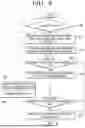


Sources:
- United States Patent and Trademark Office - verify current appl. status at the USPTO↗
Similar patent applications:
- » 20060230544
Drum type washing machine and controlling method thereof - » 20060191077
Washing machine and control method thereof - » 10719012
Washing machine and control method thereof - » 20060021154
Washing machine and control method thereof - » 20050034250
Heating apparatus of washing machine and control method thereof - » 20050081308
Washing machine and control method thereof - » 20050132503
Washing machine and control method thereof - » 20050144735
Washing machine and control method thereof - » 10878015
Washing machine and controlling method thereof - » 20060277690
Washing machine and control method thereof
Recent applications in this class:
- » 20260146380 2026-05-28
WASHING MACHINE AND CONTROLLING METHOD FOR THE SAME - » 20260062848 2026-03-05
BALANCED AND UNBALANCED LOAD DETECTION - » 20260028761 2026-01-29
LOAD REDISTRIBUTION PROCEDURE FOR A WASHING MACHINE APPLIANCE - » 20260002305 2026-01-01
METHOD FOR PREVENTING SPIN OUT-OF-BALANCE CONDITIONS IN A WASHING MACHINE APPLIANCE - » 20250333895 2025-10-30
METHOD AND DEVICE FOR DETECTING AND AVOIDING RESONANCE DURING CYCLE OF WASHER - » 20250257510 2025-08-14
CLOTHES TREATMENT APPARATUS AND METHOD OF CONTROLLING THE SAME - » 20250188663 2025-06-12
WASHING MACHINE APPLIANCE NON-SHEDDING LOAD DETECTION - » 20250146201 2025-05-08
WASHING MACHINE AND METHOD FOR CONTROLLING WASHING MACHINE - » 20250137184 2025-05-01
ACTUATOR FOR THE ACTIVE BALANCING OF A WASHING MACHINE - » 20250129530 2025-04-24
WASHING MACHINE AND METHOD FOR CONTROLLING SAME