DETECTING ANOMALIES IN WELLBORE DRILLING OPERATIONS
US20260185441A1
2026-07-02
19/008,544
2025-01-02
Smart Summary: Methods and systems are designed to find problems during wellbore drilling operations. They collect data from sensors that measure how the drilling is going, including information about the drill bit and the wellbore itself. This data is then analyzed using scientific models to spot any unusual patterns or issues. If any anomalies are detected, a warning signal is sent out to check the sensors for accuracy. This helps ensure that drilling operations run smoothly and safely. 🚀 TL;DR
Abstract:
Example methods and systems for detecting anomalies in wellbore drilling operations are disclosed. One example method includes obtaining, from one or more sensors, field data measured during a drilling operation of a wellbore, where the field data includes drilling data of a drill bit used to drill the wellbore and logging data of the wellbore. The field data is monitored based on one or more physics-based models to detect one or more anomalies in the field data. In response to a detection of the one or more anomalies in the field data, a warning signal is sent to check the one or more sensors.
Inventors:
- Guodong Zhan 83 🇸🇦 Dhahran, Saudi Arabia
- Mahmoud Abughaban 3 🇸🇦 Dhahran, Saudi Arabia
- Trieu Phat Luu 3 🇺🇸 Houston, TX, United States
- Xu Huang 1 🇺🇸 Houston, TX, United States
- Yazeed S. Qahtani 1 🇸🇦 Dhahran, Saudi Arabia
- John Bomidi 1 🇺🇸 Houston, TX, United States
Applicant:
Interested in similar patents?
Get notified when new applications in this technology area are published.
Classification:
E21B45/00 » CPC main
Measuring the drilling time or rate of penetration
E21B44/00 » CPC further
Automatic control, surveying or testing
E21B44/00 » CPC further
Automatic control systems specially adapted for drilling operations, i.e. self-operating systems which function to carry out or modify a drilling operation without intervention of a human operator, e.g. computer-controlled drilling systems ; Systems specially adapted for monitoring a plurality of drilling variables or conditions
E21B49/005 » CPC further
Testing the nature of borehole walls; Formation testing; Methods or apparatus for obtaining samples of soil or well fluids, specially adapted to earth drilling or wells Testing the nature of borehole walls or the formation by using drilling mud or cutting data
E21B2200/20 » CPC further
Special features related to earth drilling for obtaining oil, gas or water Computer models or simulations, e.g. for reservoirs under production, drill bits
E21B49/00 IPC
Testing the nature of borehole walls; Formation testing; Methods or apparatus for obtaining samples of soil or well fluids, specially adapted to earth drilling or wells
Description
TECHNICAL FIELD
The present disclosure relates to computer-implemented methods and systems for detecting anomalies in wellbore drilling operations.
BACKGROUND
Hydrocarbon wellbore drilling performance can be affected by many factors, for example, by the type of rock formation of a wellbore. In hard and heterogeneous rock formations, drill bit can experience excessive cutter wear leading to relatively short drilling footage and high drilling cost. Improving drilling performance based on dull analysis or human experience can be subjective and complicated by changes in rock formation or drilling data. Application of physics-based models, for example, drill bit wear models and drilling rate of penetration (ROP) models, can not only improve bit design efficiency, but also reduce drilling time and cost, by adjusting operational drilling parameters in real-time during drilling operations, based on the drill bit wear models and the drilling ROP models.
SUMMARY
The present disclosure involves methods and systems for detecting anomalies in wellbore drilling operations. One example method includes obtaining, from one or more sensors, field data measured during a drilling operation of a wellbore, where the field data includes drilling data of a drill bit used to drill the wellbore and logging data of the wellbore. The field data is monitored based on one or more physics-based models to detect one or more anomalies in the field data. In response to a detection of the one or more anomalies in the field data, a warning signal is sent to check the one or more sensors.
The previously described implementation is implementable using a computer-implemented method; a non-transitory, computer-readable medium storing computer-readable instructions to perform the computer-implemented method; and a computer system including a computer memory interoperably coupled with a hardware processor configured to perform the computer-implemented method or the instructions stored on the non-transitory, computer-readable medium. These and other embodiments may each optionally include one or more of the following features.
In some implementations, the one or more physics-based models include at least one of a geomechanics model, a drill bit wear model, or a drilling rate of penetration (ROP) model.
In some implementations, the drilling data of the drill bit includes at least one of revolutions per minute (RPM) data, rate of penetration (ROP) data, weight on bit (WOB) data, or torque on bit (TOB) data.
In some implementations, the logging data of the wellbore includes at least one of Gamma, porosity, density, or resistivity of rock formation of the wellbore.
In some implementations, the logging data includes logging while drilling (LWD) data of the wellbore obtained during the drilling operation of the wellbore.
In some implementations, the one or more physics-based models include a geomechanics model, and monitoring the field data includes determining, based on the geomechanics model and the field data, one or more properties of rock formation of the wellbore; determining that at least one of the one or more properties of rock formation of the wellbore is outside a predetermined range; and in response to determining that at least one of the one or more properties of rock formation of the wellbore is outside the predetermined range, determining that at least one of the one or more anomalies exists in the field data.
In some implementations, monitoring the field data includes determining that trends of two types of the logging data are opposite of each other; and in response to determining that at least two trends of two types of the logging data are not consistent, determining that at least one of the one or more anomalies exists in the field data.
In some implementations, monitoring the field data includes determining that there is missing data in the logging data; predicting, as predicted data and based on the logging data and the one or more physics-based models, the missing data; and filling the missing data with the predicted data.
In some implementations, the one or more physics-based models include a drill bit wear model, and monitoring the field data includes determining, based on the drill bit wear model and the drilling data of the drill bit, a bit wear area of the drill bit; determining that the bit wear area decreases when a drilling distance of the drill bit increases; and in response to determining that the bit wear area decreases when the drilling distance of the drill bit increases, determining that at least one of the one or more anomalies exists in the field data.
In some implementations, the one or more physics-based models include a drilling rate of penetration (ROP) model, and monitoring the field data includes predicting, based on the drilling ROP model and the drilling data of the drill bit, a drilling ROP; determining that a difference between the predicted drilling ROP and a measured drilling ROP in the drilling data is more than a predetermined threshold; and in response to determining that the difference between the predicted drilling ROP and the measured drilling ROP in the drilling data is more than the predetermined threshold, determining that at least one of the one or more anomalies exists in the field data.
While generally described as computer-implemented software embodied on tangible media that processes and transforms the respective data, some or all of the aspects may be computer-implemented methods or further included in respective systems or other devices for performing this described functionality. The details of these and other aspects and implementations of the present disclosure are set forth in the accompanying drawings and the description below. Other features, objects, and advantages of the disclosure will be apparent from the description and drawings, and from the claims.
BRIEF DESCRIPTION OF DRAWINGS
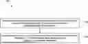
FIG. 1 illustrates an example process of detecting anomalies during a drilling operation of a wellbore, according to some implementations.
FIG. 2 illustrates an example process of monitoring field data during a drilling operation of a wellbore, according to some implementations.
FIG. 3 is a block diagram of an example computer system that can be used to provide computational functionalities associated with described algorithms, methods, functions, processes, flows, and procedures, according to some implementations.
FIG. 4 illustrates hydrocarbon production operations that include both one or more field operations and one or more computational operations, which exchange information and control exploration for the production of hydrocarbons, according to some implementations.
Like reference numbers and designations in the various drawings indicate like elements.
DETAILED DESCRIPTION
Field data measured by surface or downhole sensors in hydrocarbon drilling applications, for example, drilling data of a drill bit used to drill a wellbore or logging data of the wellbore, can be contaminated by drilling noise, missing data, or faulty measurements. In some cases, the missing data or faulty measurements may be due to issues associated with the surface or downhole sensors used to measure the field data. Monitoring the quality of the field data can be important in detecting anomalies in the field data and therefore issues associated with the surface or downhole sensors.
This disclosure describes systems and methods for using physics-based models to monitor field data obtained in hydrocarbon drilling operations and detect anomalies in the field data. Sensors used to measure field data, which detected anomalies can then be checked for issues to be fixed, in order to ensure that anomaly-free field data can be generated by the sensors. Field data free of anomalies can be used as input data in many hydrocarbon applications, for example, in training machine learning models used for pre-well drilling planning or real-time hydrocarbon field prediction. In some cases, the trained machine learning models can be used to 1) predict the drilling dysfunctions, for example, by predicting the drilling vibrations from surface data when downhole vibration measurement data is not available; 2) predict downhole loggings, for example, by predicting downhole gamma logging using surface data when gamma logging tool fails; 3) predict downhole bit wear for tripping planning; and/or 4) predict other drilling abnormalities.
In some cases, the physics-based models can include a geomechanics model, a physics-based drill bit wear model, or a drilling ROP model. The physics-based models can be used to perform monitoring, correction, or missing data fulfilling of the surface or downhole drilling data or logging data. The physics-based models can also be used to apply lower or upper limits to the field data to filter or correct the field data, based on prior knowledge.
The disclosed systems and methods provide many advantages over existing systems. As an example, the disclosed method can detect anomalies in field data and improve the quality of field data that can be used for other hydrocarbon applications, such as training machine learning models used for pre-well drilling planning or real-time hydrocarbon field prediction. As another example, the disclosed method can use physics-based models to detect anomalies in field data and improve the performance of drilling operations by ensuring that field data measured by the surface or downhole sensors reflect the real-time conditions of the drilling operations.
FIG. 1 illustrates an example process 100 of detecting anomalies during a drilling operation of a wellbore, according to some implementations. For convenience, process 100 will be described as being performed by a computer system having one or more computers located in one or more locations and programmed appropriately in accordance with this specification. An example of the computer system is the computer system 300 illustrated in FIG. 3.
At 102, a computer system obtains, from one or more sensors, raw field data during a drilling operation of a wellbore, where the field data includes drilling data of a drill bit used to drill the wellbore and logging data of the wellbore. In some implementations, the drilling data of the drill bit can include revolutions per minute (RPM) data, rate of penetration (ROP) data, weight on bit (WOB) data, torque on bit (TOB) data, or drilling distance data of the drill bit measured, for example, in real-time, during the drilling operation. The logging data of the wellbore (e.g., logging while drilling (LWD) data) can include Gamma, porosity, density, or resistivity of rock formation of the wellbore, and can also be measured in real-time during the drilling operation.
At 104, the computer system monitors, based on one or more physics-based models, the raw field data to detect one or more anomalies in the raw field data, and sends warning signals to check the one or more sensors, when the anomalies are detected. In some cases, the one or more physics-based models can include at least one of a geomechanics model, a drill bit wear model, or a drilling ROP model.
In some implementations, the computer system can utilize a geomechanics model to predict properties of rock formation of a wellbore (e.g., uniaxial compressive strength (UCS) or friction angle (FA) of the rock formation), using the logging data (e.g., acoustic wave measurement) of the wellbore that is measured during the drilling operation. In some cases, an acoustic sensor can measure the compressive wave velocity or shear wave velocity in the rock formation. Then the computer system can use the geomechanics model, with the measured compressive wave velocity or shear wave velocity as input to the geomechanics model, to predict properties of the rock formation, for example, the rock compressive strength or UCS value of the rock formation.
In some implementations, the computer system can monitor the predicted properties of the rock formation of the wellbore to determine if the predicted rock formation properties are within predetermined ranges. If one or more predicted rock formation properties are outside one or more predetermined ranges, the computer system can send a warning signal to indicate that the measured logging data may have an anomaly, and the one or more sensors can then be checked for issues in measuring the logging data. In some cases, the predetermined ranges depend on the type of rock formation and the application associated with the drilling operation. For example, a rock formation of shale can have an UCS range of 5,000-6,000 psi, and a rock formation of sandstone can have an UCS range of UCS 20,000-30,000 psi. In some cases, the UCS range of a rock formation can depend on the application associated with the drilling operation. For example, the sandstone in the United States of America can be different from the sandstone in the Kingdom of Saudi Arabia (KSA). In some cases, the predetermined ranges of rock formation properties in a target application can be jointed determined by the representative rock formation property ranges of the same type of rock formation and previous rock formation property measurements in the same region of the target application.
In some implementations, the computer system can monitor the trend of each type of the measured logging data, for example, the mean value of each type of the measured logging data, to determine if the trends of different types of the measured logging data are consistent. For example, decreased measured Gamma over time can correspond to decreased measured porosity over time. As another example, in an application where the rock formation of the wellbore is mostly sandstone and shale, an increase of measured Gamma data can correspond to an increase in the percentage of shale in the rock formation. Then the measured porosity can decrease due to the lower porosity of the shale when compared to the porosity of the sandstone.
In some cases, if the computer system determines that the trends of two types of the measured logging data are opposite of each other (e.g., one trend is increasing and another trend is decreasing), the computer system can send a warning signal to indicate that the measured logging data may have an anomaly, and the one or more sensors can then be checked for issues in measuring the logging data. The consistency check between trends of different types of the measured logging data can be applied to different pairs of the measured logging data, for example, between density and Gamma, density and porosity, Gamma and porosity, or resistivity and porosity.
In some implementations, the computer system can monitor the measured logging data to determine if there is missing logging data in the measured logging data. If the computer system determines that there is missing logging data, the computer system can predict the missing logging data (e.g., Gamma data) using the measured logging data that is available (e.g., measured porosity data or density data), using regression fitting of the measured logging data or a machine learning model. In some cases, the machine learning model can be trained using offset well data. In some cases, for real-time modeling, if the Gamma data is missing in the measured logging data, the machine learning model can use the measured porosity or density data to predict Gamma data, and then use the predicted Gamma data to fill the missing Gamma data.
In some implementation, the computer system can check whether a machine learning model or a regression fitting based model can be built to predict the missing logging data using measured logging data or drilling data that is available. For example, using offset well data that is available, the computer system can utilize the machine learning model or the regression fitting based model to check if the Gamma, density, ROP, or WOB data can predict porosity of the rock formation. If a prediction model can be built, then missing porosity data can be filled using the other measured logging data or drilling data that is available.
In some implementations, the computer system can use a drill bit wear model to determine a bit wear area or volume of a drill bit used to drill a wellbore, by applying drilling data of the drill bit that is measured, for example, in real-time, by one or more sensors during a drilling operation of the wellbore, to the drill bit wear model. In some cases, the drill bit wear model can be a physics-based model or a data-driven machine learning model. A physics-based drill bit wear model can determine the bit wear area or volume using cutting mechanics and thermal-mechanical physics. A data-driven machine learning model can determine the bit wear area or volume using drilling data as the input, for example, RPM, ROP, WOB, or drilling distance of the drill bit during the drilling operation. In some cases, the data-driven machine learning based drill bit wear model can be trained using drilling data obtained from drilling operations of offset wells of the wellbore.
In some implementations, the bit wear of a drill bit increases as the drilling distance of the drill bit increases. In some cases, if the drill bit wear model determines a decrease of a wear area of the drill bit while the drilling distance increases, then the computer system can send a warning signal to indicate that the measured drilling data may have an anomaly, and the one or more sensors can then be checked for issues in measuring the drilling data. For example, if the wear area or volume of the drill bit determined by the drill bit wear model decreased by 5% when the drilling distance of the drill bit increased by 10 feet, the computer system can send a warning signal to indicate that the measured drilling data may have an anomaly. As another example, if the predicted wear state changes from a “worn” state to a “new” state during a drilling operation, the computer system can send a warning signal to indicate that the measured drilling data may have an anomaly.
In some implementations, the computer system can monitor raw field data (e.g., drilling data of a drill bit used to drill a wellbore or logging data (e.g., LWD data) of the wellbore) that is measured, for example, in real-time, by one or more sensors during a drilling operation of the wellbore, and determine that an anomaly exists in measured drilling ROP in the drilling data, if changes in part the raw field data (e.g., RPM or WOB of the drill bit in the drilling data) and rock properties of the wellbore in the logging data are within predetermined ranges, whereas a change in the measured drilling ROP in the drilling data is more than a predetermined threshold (e.g., 10%) during a preset period of time, or when the measured drilling ROP increases while the drilling distance is increasing. When the computer system determines that the anomaly exists in measured drilling ROP, the computer system can send a warning signal to indicate that the measured drilling ROP has an anomaly, and the one or more sensors can then be checked for issues in measuring the raw field data. In some cases, the warning signal can include the information of the detected anomaly. For example, the warning signal can include a message indicating that the measured drilling ROP increases as drilling distance increases with the same rock formation logging.
In some implementations, the computer system can utilize a drilling ROP model to monitor raw field data (e.g., drilling data of the drill bit or logging data (e.g., LWD data) of the wellbore) that is measured, for example, in real-time, by one or more sensors during a drilling operation of the wellbore, or detect one or more anomalies in the drilling data or the logging data. In some cases, the drilling ROP model can determine drilling ROP using cutting mechanics and thermal-mechanical physics. The computer system can apply the drilling ROP model to the drilling data (e.g., WOB, RPM, or drilling distance data) of the drill bit or rock formation data (e.g., rock UCS) obtained from one or more offset wells of the wellbore to determine a drilling ROP during the drilling operation, and compare the determined drilling ROP with the measured drilling ROP in the raw field data. If a difference between the determined drilling ROP and the measured drilling ROP is larger than a predetermined threshold, the computer system can send a warning signal to indicate that the raw field data has anomalies, and the one or more sensors can then be checked for issues in measuring the raw field data. An example of the predetermined threshold can be 30% of the determined drilling ROP or the measured drilling ROP. In some cases, the drilling ROP model can be used to generate the determined drilling ROP, as described above, when changes in part of the drilling data (e.g., RPM or WOB of the drill bit) or part of the logging data (e.g., rock properties of the wellbore) are more than a predetermined range during a preset period of time.
In some implementations, lower or upper limits can be applied to the field data based on prior knowledge to filter or correct the field data. In some cases, for a hydrocarbon field application, offset well information can be obtained for logging data, drilling data or formation data. For example, if a section to be drilled in a target hydrocarbon field is mainly sandstone, and based on offset well information, for sandstone drilling in the target hydrocarbon field, the Gamma is in the range of 20-80, and the drilling ROP is in the range of 3-25 feet/hour, then for field data measured during a drilling operation of a new wellbore in the section, the field data can be checked, filtered, or corrected based on the aforementioned ranges to ensure that the sensors or logging tools used to measure the field data are working properly, before the field data is used for other applications.
In some implementations, after issues of the surface or downhole sensors that lead to the detected anomalies in the field data have been fixed, the anomaly-free field data measured by the surface and downhole sensors (e.g., drilling data of the drill bit and logging data of the wellbore) can be used as data for other hydrocarbon applications, for example, to train machine learning models for pre-well drilling planning or real-time hydrocarbon field prediction. In some cases, the trained machine learning models can be used to 1) predict the drilling dysfunctions, for example, by predicting the drilling vibrations from surface data when downhole vibration measurement data is not available; 2) predict downhole loggings, for example, by predicting downhole gamma logging using surface data when gamma logging tool fails; 3) predict downhole bit wear for tripping planning; and/or 4) predict other drilling abnormalities.
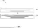
FIG. 2 illustrates an example process 200 of monitoring field data during a drilling operation of a wellbore, according to some implementations. For convenience, process 200 will be described as being performed by a computer system having one or more computers located in one or more locations and programmed appropriately in accordance with this specification. An example of the computer system is the computer system 300 illustrated in FIG. 3.
At 202, a computer system obtains, from one or more sensors, field data measured during a drilling operation of a wellbore, where the field data includes drilling data of a drill bit used to drill the wellbore and logging data of the wellbore.
At 204, the computer system monitors, based on one or more physics-based models, the field data to detect one or more anomalies in the field data.
At 206, in response to detecting the one or more anomalies in the field data, the computer system sends a warning signal to check the one or more sensors.
FIG. 3 is a block diagram of an example computer system 300 that can be used to provide computational functionalities associated with described algorithms, methods, functions, processes, flows, and procedures, according to some implementations of the present disclosure. In some implementations, the computer system performing process 100 or 200 can be the computer system 300, include the computer system 300, or the computer system performing process 100 or 200 can communicate with the computer system 300.
The illustrated computer 302 is intended to encompass any computing device such as a server, a desktop computer, an embedded computer, a laptop/notebook computer, a wireless data port, a smart phone, a personal data assistant (PDA), a tablet computing device, or one or more processors within these devices, including physical instances, virtual instances, or both. The computer 302 can include input devices such as keypads, keyboards, and touch screens that can accept user information. Also, the computer 302 can include output devices that can convey information associated with the operation of the computer 302. The information can include digital data, visual data, audio information, or a combination of information. The information can be presented in a GUI or other user interface. In some implementations, the inputs and outputs include display ports (such as DVI-I+2x display ports), USB 3.0, GbE ports, isolated DI/O, SATA-III (6.0 Gb/s) ports, mPCIe slots, a combination of these, or other ports. In instances of an edge gateway, the computer 302 can include a Smart Embedded Management Agent (SEMA), such as a built-in ADLINK SEMA 2.2, and a video sync technology, such as Quick Sync Video technology supported by ADLINK MSDK+. In some examples, the computer 302 can include the MXE-5400 Series processor-based fanless embedded computer by ADLINK, though the computer 302 can take other forms or include other components.
The computer 302 can serve in a role as a client, a network component, a server, a database, a persistency, or components of a computer system for performing the subject matter described in the present disclosure. The illustrated computer 302 is communicably coupled with a network 330. In some implementations, one or more components of the computer 302 can be configured to operate within different environments, including cloud-computing-based environments, local environments, global environments, and combinations of environments.
At a high level, the computer 302 is an electronic computing device operable to receive, transmit, process, store, and manage data and information associated with the described subject matter. According to some implementations, the computer 302 can also include, or be communicably coupled with, an application server, an email server, a web server, a caching server, a streaming data server, or a combination of servers.
The computer 302 can receive requests over network 330 from a client application (for example, executing on another computer 302). The computer 302 can respond to the received requests by processing the received requests using software applications. Requests can also be sent to the computer 302 from internal users (for example, from a command console), external (or third) parties, automated applications, entities, individuals, systems, and computers.
Each of the components of the computer 302 can communicate using a system bus 303. In some implementations, any or all of the components of the computer 302, including hardware or software components, can interface with each other or the interface 304 (or a combination of both), over the system bus. Interfaces can use an application programming interface (API) 312, a service layer 313, or a combination of the API 312 and service layer 313. The API 312 can include specifications for routines, data structures, and object classes. The API 312 can be either computer-language independent or dependent. The API 312 can refer to a complete interface, a single function, or a set of APIs 312.
The service layer 313 can provide software services to the computer 302 and other components (whether illustrated or not) that are communicably coupled to the computer 302. The functionality of the computer 302 can be accessible for all service consumers using this service layer 313. Software services, such as those provided by the service layer 313, can provide reusable, defined functionalities through a defined interface. For example, the interface can be software written in JAVA, C++, or a language providing data in extensible markup language (XML) format. While illustrated as an integrated component of the computer 302, in alternative implementations, the API 312 or the service layer 313 can be stand-alone components in relation to other components of the computer 302 and other components communicably coupled to the computer 302. Moreover, any or all parts of the API 312 or the service layer 313 can be implemented as child or sub-modules of another software module, enterprise application, or hardware module without departing from the scope of the present disclosure.
The computer 302 can include an interface 304. Although illustrated as a single interface 304 in FIG. 3, two or more interfaces 304 can be used according to particular needs, desires, or particular implementations of the computer 302 and the described functionality. The interface 304 can be used by the computer 302 for communicating with other systems that are connected to the network 330 (whether illustrated or not) in a distributed environment. Generally, the interface 304 can include, or be implemented using, logic encoded in software or hardware (or a combination of software and hardware) operable to communicate with the network 330. More specifically, the interface 304 can include software supporting one or more communication protocols associated with communications. As such, the network 330 or the interface's hardware can be operable to communicate physical signals within and outside of the illustrated computer 302.
The computer 302 includes a processor 305. Although illustrated as a single processor 305 in FIG. 3, two or more processors 305 can be used according to particular needs, desires, or particular implementations of the computer 302 and the described functionality. Generally, the processor 305 can execute instructions and manipulate data to perform the operations of the computer 302, including operations using algorithms, methods, functions, processes, flows, and procedures as described in the present disclosure.
The computer 302 can also include a database 306 that can hold data for the computer 302 and other components connected to the network 330 (whether illustrated or not). For example, database 306 can be an in-memory, conventional, or a database storing data consistent with the present disclosure. In some implementations, the database 306 can be a combination of two or more different database types (for example, hybrid in-memory and conventional databases) according to particular needs, desires, or particular implementations of the computer 302 and the described functionality. Although illustrated as a single database 306 in FIG. 3, two or more databases (of the same, different, or combination of types) can be used according to particular needs, desires, or particular implementations of the computer 302 and the described functionality. While database 306 is illustrated as an internal component of the computer 302, in alternative implementations, database 306 can be external to the computer 302.
The computer 302 also includes a memory 307 that can hold data for the computer 302 or a combination of components connected to the network 330 (whether illustrated or not). Memory 307 can store any data consistent with the present disclosure. In some implementations, memory 307 can be a combination of two or more different types of memory (for example, a combination of semiconductor and magnetic storage) according to particular needs, desires, or particular implementations of the computer 302 and the described functionality. Although illustrated as a single memory 307 in FIG. 3, two or more memories 307 (of the same, different, or combination of types) can be used according to particular needs, desires, or particular implementations of the computer 302 and the described functionality. While memory 307 is illustrated as an internal component of the computer 302, in alternative implementations, memory 307 can be external to the computer 302.
An application 308 can be an algorithmic software engine providing functionality according to particular needs, desires, or particular implementations of the computer 302 and the described functionality. For example, an application 308 can serve as one or more components, modules, or applications 308. Multiple applications 308 can be implemented on the computer 302. Each application 308 can be internal or external to the computer 302.
The computer 302 can also include a power supply 314. The power supply 314 can include a rechargeable or non-rechargeable battery that can be configured to be either user- or non-user-replaceable. In some implementations, the power supply 314 can include power-conversion and management circuits, including recharging, standby, and power management functionalities. In some implementations, the power-supply 314 can include a power plug to allow the computer 302 to be plugged into a wall socket or a power source to, for example, power the computer 302 or recharge a rechargeable battery.
There can be any number of computers 302 associated with, or external to, a computer system including computer 302, with each computer 302 communicating over network 330. Further, the terms “client”, “user”, and other appropriate terminology can be used interchangeably without departing from the scope of the present disclosure. Moreover, the present disclosure contemplates that many users can use one computer 302 and one user can use multiple computers 302.
FIG. 4 illustrates hydrocarbon production operations 400 that include both one or more field operations 410 and one or more computational operations 412, which exchange information and control exploration for the production of hydrocarbons, according to some implementations. In some implementations, outputs of techniques of the present disclosure can be performed before, during, or in combination with the hydrocarbon production operations 400, specifically, for example, either as field operations 410 or computational operations 412, or both.
Examples of field operations 410 include forming/drilling a wellbore, hydraulic fracturing, producing through the wellbore, injecting fluids (such as water) through the wellbore, to name a few. In some implementations, methods of the present disclosure can trigger or control the field operations 410. For example, the methods of the present disclosure can generate data from hardware/software including sensors and physical data gathering equipment (e.g., seismic sensors, well logging tools, flow meters, and temperature and pressure sensors). The methods of the present disclosure can include transmitting the data from the hardware/software to the field operations 410 and responsively triggering the field operations 410 including, for example, generating plans and signals that provide feedback to and control physical components of the field operations 410. Alternatively, or in addition, the field operations 410 can trigger the methods of the present disclosure. For example, implementing physical components (including, for example, hardware, such as sensors) deployed in the field operations 410 can generate plans and signals that can be provided as input or feedback (or both) to the methods of the present disclosure.
Examples of computational operations 412 include one or more computer systems 420 that include one or more processors and computer-readable media (e.g., non-transitory computer-readable media) operatively coupled to the one or more processors to execute computer operations to perform the methods of the present disclosure. The computational operations 412 can be implemented using one or more databases 418, which store data received from the field operations 410 or generated internally within the computational operations 412 (e.g., by implementing the methods of the present disclosure) or both. For example, the one or more computer systems 420 process inputs from the field operations 410 to assess conditions in the physical world, the outputs of which are stored in the databases 418. For example, seismic sensors of the field operations 410 can be used to perform a seismic survey to map subterranean features, such as facies and faults. In performing a seismic survey, seismic sources (e.g., seismic vibrators or explosions) generate seismic waves that propagate in the earth and seismic receivers (e.g., geophones) measure reflections generated as the seismic waves interact with boundaries between layers of a subsurface formation. The source and received signals are provided to the computational operations 412 where they are stored in the databases 418 and analyzed by the one or more computer systems 420.
In some implementations, one or more outputs 422 generated by the one or more computer systems 420 can be provided as feedback/input to the field operations 410 (either as direct input or stored in the databases 418). The field operations 410 can use the feedback/input to control physical components used to perform the field operations 410 in the real world.
For example, the computational operations 412 can process the seismic data to generate three-dimensional maps of the subsurface formation. The computational operations 412 can use these 3D maps to provide plans for locating and drilling exploratory wells. In some operations, the exploratory wells are drilled using logging-while-drilling (LWD) techniques which incorporate logging tools into the drill string. LWD techniques can enable the computational operations 412 to process new information about the formation and control the drilling to adjust to the observed conditions in real-time.
The one or more computer systems 420 can update the 3D maps of the subsurface formation as information from one exploration well is received and the computational operations 412 can adjust the location of the next exploration well based on the updated 3D maps. Similarly, the data received from production operations can be used by the computational operations 412 to control components of the production operations. For example, production well and pipeline data can be analyzed to predict slugging in pipelines leading to a refinery and the computational operations 412 can control machine operated valves upstream of the refinery to reduce the likelihood of plant disruptions that run the risk of taking the plant offline.
In some implementations of the computational operations 412, customized user interfaces can present intermediate or final results of the above-described processes to a user. Information can be presented in one or more textual, tabular, or graphical formats, such as through a dashboard. The information can be presented at one or more on-site locations (such as at an oil well or other facility), on the Internet (such as on a webpage), on a mobile application (or app), or at a central processing facility.
The presented information can include feedback, such as changes in parameters or processing inputs, that the user can select to improve a production environment, such as in the exploration, production, or testing of petrochemical processes or facilities. For example, the feedback can include parameters that, when selected by the user, can cause a change to, or an improvement in, drilling parameters (including drill bit speed and direction) or overall production of a gas or oil well. The feedback, when implemented by the user, can improve the speed and accuracy of calculations, streamline processes, improve models, and solve problems related to efficiency, performance, safety, reliability, costs, downtime, and the need for human interaction.
In some implementations, the feedback can be implemented in real-time, such as to provide an immediate or near-immediate change in operations or in a model. The term real-time (or similar terms as understood by one of ordinary skill in the art) means that an action and a response are temporally proximate such that an individual perceives the action and the response occurring substantially simultaneously. For example, the time difference for a response to display (or for an initiation of a display) of data following the individual's action to access the data can be less than 1 millisecond (ms), less than 1 second(s), or less than 5 s. While the requested data need not be displayed (or initiated for display) instantaneously, it is displayed (or initiated for display) without any intentional delay, taking into account processing limitations of a described computing system and time required to, for example, gather, accurately measure, analyze, process, store, or transmit the data.
Events can include readings or measurements captured by downhole equipment such as sensors, pumps, bottom hole assemblies, or other equipment. The readings or measurements can be analyzed at the surface, such as by using applications that can include modeling applications and machine learning. The analysis can be used to generate changes to settings of downhole equipment, such as drilling equipment. In some implementations, values of parameters or other variables that are determined can be used automatically (such as through using rules) to implement changes in oil or gas well exploration, production/drilling, or testing. For example, outputs of the present disclosure can be used as inputs to other equipment or systems at a facility. This can be especially useful for systems or various pieces of equipment that are located several meters or several miles apart, or are located in different countries or other jurisdictions.
Implementations of the subject matter and the functional operations described in this specification can be implemented in digital electronic circuitry, in tangibly embodied computer software or firmware; in computer hardware, including the structures disclosed in this specification and their structural equivalents; or in combinations of one or more of them. Software implementations of the described subject matter can be implemented as one or more computer programs. Each computer program can include one or more modules of computer program instructions encoded on a tangible, non-transitory, computer-readable computer-storage medium for execution by, or to control the operation of, data processing apparatus. Alternatively, or additionally, the program instructions can be encoded in/on an artificially generated propagated signal. For example, the signal can be a machine-generated electrical, optical, or electromagnetic signal that is generated to encode information for transmission to a suitable receiver apparatus for execution by a data processing apparatus. The computer-storage medium can be a machine-readable storage device, a machine-readable storage substrate, a random or serial access memory device, or a combination of computer-storage mediums.
The terms “data processing apparatus”, “computer”, and “electronic computer device” (or equivalent as understood by one of ordinary skill in the art) refer to data processing hardware. For example, a data processing apparatus can encompass all kinds of apparatuses, devices, and machines for processing data, including by way of example, a programmable processor, a computer, or multiple processors or computers. The apparatus can also include special purpose logic circuitry including, for example, a central processing unit (CPU), a field programmable gate array (FPGA), or an application specific integrated circuit (ASIC). In some implementations, the data processing apparatus or special purpose logic circuitry (or a combination of the data processing apparatus and special purpose logic circuitry) can be hardware-or software-based (or a combination of both hardware-and software-based). The apparatus can optionally include code that creates an execution environment for computer programs, for example, code that constitutes processor firmware, a protocol stack, a database management system, an operating system, or a combination of execution environments. The present disclosure contemplates the use of data processing apparatuses with or without conventional operating systems, for example, Linux, Unix, Windows, Mac OS, Android, or iOS.
A computer program, which can also be referred to or described as a program, software, a software application, a module, a software module, a script, or code can be written in any form of programming language. Programming languages can include, for example, compiled languages, interpreted languages, declarative languages, or procedural languages. Programs can be deployed in any form, including as stand-alone programs, modules, components, subroutines, or units for use in a computing environment. A computer program can, but need not, correspond to a file in a file system. A program can be stored in a portion of a file that holds other programs or data, for example, one or more scripts stored in a markup language document; in a single file dedicated to the program in question; or in multiple coordinated files storing one or more modules, sub programs, or portions of code. A computer program can be deployed for execution on one computer or on multiple computers that are located, for example, at one site or distributed across multiple sites that are interconnected by a communication network. While portions of the programs illustrated in the various figures may be shown as individual modules that implement the various features and functionality through various objects, methods, or processes; the programs can instead include a number of sub-modules, third-party services, components, and libraries. Conversely, the features and functionality of various components can be combined into single components as appropriate. Thresholds used to make computational determinations can be statically, dynamically, or both statically and dynamically determined.
The methods, processes, or logic flows described in this specification can be performed by one or more programmable computers executing one or more computer programs to perform functions by operating on input data and generating output. The methods, processes, or logic flows can also be performed by, and apparatus can also be implemented as, special purpose logic circuitry, for example, a CPU, an FPGA, or an ASIC.
Computers suitable for the execution of a computer program can be based on one or more of general and special purpose microprocessors and other kinds of CPUs. The elements of a computer are a CPU for performing or executing instructions and one or more memory devices for storing instructions and data. Generally, a CPU can receive instructions and data from (and write data to) a memory. A computer can also include, or be operatively coupled to, one or more mass storage devices for storing data. In some implementations, a computer can receive data from, and transfer data to, the mass storage devices including, for example, magnetic, magneto optical disks, or optical disks. Moreover, a computer can be embedded in another device, for example, a mobile telephone, a personal digital assistant (PDA), a mobile audio or video player, a game console, a global positioning system (GPS) receiver, or a portable storage device such as a universal serial bus (USB) flash drive.
Computer readable media (transitory or non-transitory, as appropriate) suitable for storing computer program instructions and data can include all forms of permanent/non-permanent and volatile/non-volatile memory, media, and memory devices. Computer readable media can include, for example, semiconductor memory devices such as random access memory (RAM), read only memory (ROM), phase change memory (PRAM), static random access memory (SRAM), dynamic random access memory (DRAM), erasable programmable read-only memory (EPROM), electrically erasable programmable read-only memory (EEPROM), and flash memory devices. Computer readable media can also include, for example, magnetic devices such as tape, cartridges, cassettes, and internal/removable disks. Computer readable media can also include magneto optical disks, optical memory devices, and technologies including, for example, digital video disc (DVD), CD ROM, DVD+/−R, DVD-RAM, DVD-ROM, HD-DVD, and BLURAY. The memory can store various objects or data, including caches, classes, frameworks, applications, modules, backup data, jobs, web pages, web page templates, data structures, database tables, repositories, and dynamic information. Types of objects and data stored in memory can include parameters, variables, algorithms, instructions, rules, constraints, and references. Additionally, the memory can include logs, policies, security or access data, and reporting files. The processor and the memory can be supplemented by, or incorporated in, special purpose logic circuitry.
Implementations of the subject matter described in the present disclosure can be implemented on a computer having a display device for providing interaction with a user, including displaying information to (and receiving input from) the user. Types of display devices can include, for example, a cathode ray tube (CRT), a liquid crystal display (LCD), a light-emitting diode (LED), or a plasma monitor. Display devices can include a keyboard and pointing devices including, for example, a mouse, a trackball, or a trackpad. User input can also be provided to the computer through the use of a touchscreen, such as a tablet computer surface with pressure sensitivity or a multi-touch screen using capacitive or electric sensing. Other kinds of devices can be used to provide for interaction with a user, including to receive user feedback, for example, sensory feedback including visual feedback, auditory feedback, or tactile feedback. Input from the user can be received in the form of acoustic, speech, or tactile input. In addition, a computer can interact with a user by sending documents to, and receiving documents from, a device that is used by the user. For example, the computer can send web pages to a web browser on a user's client device in response to requests received from the web browser.
The term “graphical user interface,” or “GUI,” can be used in the singular or the plural to describe one or more graphical user interfaces and each of the displays of a particular graphical user interface. Therefore, a GUI can represent any graphical user interface, including, but not limited to, a web browser, a touch screen, or a command line interface (CLI) that processes information and efficiently presents the information results to the user. In general, a GUI can include a plurality of user interface (UI) elements, some or all associated with a web browser, such as interactive fields, pull-down lists, and buttons. These and other UI elements can be related to or represent the functions of the web browser. Implementations of the subject matter described in this specification can be implemented in a computing system that includes a back end component, for example, as a data server, or that includes a middleware component, for example, an application server. Moreover, the computing system can include a front-end component, for example, a client computer having one or both of a graphical user interface or a Web browser through which a user can interact with the computer. The components of the system can be interconnected by any form or medium of wireline or wireless digital data communication (or a combination of data communication) in a communication network. Examples of communication networks include a local area network (LAN), a radio access network (RAN), a metropolitan area network (MAN), a wide area network (WAN), Worldwide Interoperability for Microwave Access (WIMAX), a wireless local area network (WLAN) (for example, using 802.11 a/b/g/n or 802.20 or a combination of protocols), all or a portion of the Internet, or any other communication system or systems at one or more locations (or a combination of communication networks). The network can communicate with, for example, Internet Protocol (IP) packets, frame relay frames, asynchronous transfer mode (ATM) cells, voice, video, data, or a combination of communication types between network addresses.
The computing system can include clients and servers. A client and server can generally be remote from each other and can typically interact through a communication network. The relationship of client and server can arise by virtue of computer programs running on the respective computers and having a client-server relationship.
Cluster file systems can be any file system type accessible from multiple servers for read and update. Locking or consistency tracking may not be necessary since the locking of exchange file system can be done at application layer. Furthermore, Unicode data files can be different from non-Unicode data files.
While this specification contains many specific implementation details, these should not be construed as limitations on the scope of what may be claimed, but rather as descriptions of features that may be specific to particular implementations. Certain features that are described in this specification in the context of separate implementations can also be implemented, in combination, or in a single implementation. Conversely, various features that are described in the context of a single implementation can also be implemented in multiple implementations, separately, or in any suitable sub-combination. Moreover, although previously described features may be described as acting in certain combinations and even initially claimed as such, one or more features from a claimed combination can, in some cases, be excised from the combination, and the claimed combination may be directed to a sub-combination or variation of a sub-combination.
Particular implementations of the subject matter have been described. Other implementations, alterations, and permutations of the described implementations are within the scope of the following claims as will be apparent to those skilled in the art. While operations are depicted in the drawings or claims in a particular order, this should not be understood as requiring that such operations be performed in the particular order shown or in sequential order, or that all illustrated operations be performed (some operations may be considered optional), to achieve desirable results. In certain circumstances, multitasking or parallel processing (or a combination of multitasking and parallel processing) may be advantageous and performed as deemed appropriate.
Moreover, the separation or integration of various system modules and components in the previously described implementations should not be understood as requiring such separation or integration in all implementations; and it should be understood that the described program components and systems can generally be integrated together in a single software product or packaged into multiple software products.
Accordingly, the previously described example implementations do not define or constrain the present disclosure. Other changes, substitutions, and alterations are also possible without departing from the spirit and scope of the present disclosure.
Furthermore, any claimed implementation is considered to be applicable to at least a computer-implemented method; a non-transitory, computer-readable medium storing computer-readable instructions to perform the computer-implemented method; and a computer system comprising a computer memory interoperably coupled with a hardware processor configured to perform the computer-implemented method or the instructions stored on the non-transitory, computer-readable medium.
EMBODIMENTS
Embodiment 1: A computer-implemented method includes obtaining, from one or more sensors, field data measured during a drilling operation of a wellbore, where the field data includes drilling data of a drill bit used to drill the wellbore and logging data of the wellbore. The field data is monitored based on one or more physics-based models to detect one or more anomalies in the field data. In response to a detection of the one or more anomalies in the field data, a warning signal is sent to check the one or more sensors.
Embodiment 2: The computer-implemented method of embodiment 1, where the one or more physics-based models include at least one of a geomechanics model, a drill bit wear model, or a drilling rate of penetration (ROP) model.
Embodiment 3: The computer-implemented method of embodiment 1 or 2, where the drilling data of the drill bit includes at least one of revolutions per minute (RPM) data, rate of penetration (ROP) data, weight on bit (WOB) data, or torque on bit (TOB) data.
Embodiment 4: The computer-implemented method of any one of embodiments 1 to 3, where the logging data of the wellbore includes at least one of Gamma, porosity, density, or resistivity of rock formation of the wellbore.
Embodiment 5: The computer-implemented method of any one of embodiments 1 to 4, where the logging data includes logging while drilling (LWD) data of the wellbore obtained during the drilling operation of the wellbore.
Embodiment 6: The computer-implemented method of one of embodiments 1 to 5, where the one or more physics-based models include a geomechanics model, and monitoring the field data includes determining, based on the geomechanics model and the field data, one or more properties of rock formation of the wellbore; determining that at least one of the one or more properties of rock formation of the wellbore is outside a predetermined range; and in response to determining that at least one of the one or more properties of rock formation of the wellbore is outside the predetermined range, determining that at least one of the one or more anomalies exists in the field data.
Embodiment 7: The computer-implemented method of embodiment 6, where monitoring the field data includes determining that trends of two types of the logging data are opposite of each other; and in response to determining that at least two trends of two types of the logging data are not consistent, determining that at least one of the one or more anomalies exists in the field data.
Embodiment 8: The computer-implemented method of embodiment 6 or 7, where monitoring the field data includes determining that there is missing data in the logging data; predicting, as predicted data and based on the logging data and the one or more physics-based models, the missing data; and filling the missing data with the predicted data.
Embodiment 9: The computer-implemented method of any one of embodiments 1 to 8, where the one or more physics-based models include a drill bit wear model, and monitoring the field data includes determining, based on the drill bit wear model and the drilling data of the drill bit, a bit wear area of the drill bit; determining that the bit wear area decreases when a drilling distance of the drill bit increases; and in response to determining that the bit wear area decreases when the drilling distance of the drill bit increases, determining that at least one of the one or more anomalies exists in the field data.
Embodiment 10: The computer-implemented method of any one of embodiments 1 to 9, where the one or more physics-based models include a drilling rate of penetration (ROP) model, and monitoring the field data includes predicting, based on the drilling ROP model and the drilling data of the drill bit, a drilling ROP; determining that a difference between the predicted drilling ROP and a measured drilling ROP in the drilling data is more than a predetermined threshold; and in response to determining that the difference between the predicted drilling ROP and the measured drilling ROP in the drilling data is more than the predetermined threshold, determining that at least one of the one or more anomalies exists in the field data.
Embodiment 11: A non-transitory computer-readable medium storing one or more instructions executable by a computer system to perform operations including obtaining, from one or more sensors, field data measured during a drilling operation of a wellbore, where the field data includes drilling data of a drill bit used to drill the wellbore and logging data of the wellbore. The field data is monitored based on one or more physics-based models to detect one or more anomalies in the field data. In response to a detection of the one or more anomalies in the field data, a warning signal is sent to check the one or more sensors.
Embodiment 12: The non-transitory computer-readable medium of embodiment 11, where the one or more physics-based models include at least one of a geomechanics model, a drill bit wear model, or a drilling rate of penetration (ROP) model.
Embodiment 13: The non-transitory computer-readable medium of embodiment 11 or 12, where the drilling data of the drill bit includes at least one of revolutions per minute (RPM) data, rate of penetration (ROP) data, weight on bit (WOB) data, or torque on bit (TOB) data.
Embodiment 14: The non-transitory computer-readable medium of any one of embodiments 11 to 13, where the logging data of the wellbore includes at least one of Gamma, porosity, density, or resistivity of rock formation of the wellbore.
Embodiment 15: The non-transitory computer-readable medium of any one of embodiments 11 to 14, where the logging data includes logging while drilling (LWD) data of the wellbore obtained during the drilling operation of the wellbore.
Embodiment 16: A computer-implemented system, including one or more computers; and one or more computer memory devices interoperably coupled with the one or more computers and having tangible, non-transitory, machine-readable media storing one or more instructions that, when executed by the one or more computers, perform one or more operations including obtaining, from one or more sensors, field data measured during a drilling operation of a wellbore, where the field data includes drilling data of a drill bit used to drill the wellbore and logging data of the wellbore. The field data is monitored based on one or more physics-based models to detect one or more anomalies in the field data. In response to a detection of the one or more anomalies in the field data, a warning signal is sent to check the one or more sensors.
Embodiment 17: The computer-implemented system of embodiment 16, where the one or more physics-based models include at least one of a geomechanics model, a drill bit wear model, or a drilling rate of penetration (ROP) model.
Embodiment 18: The computer-implemented system of embodiment 16 or 17, where the drilling data of the drill bit includes at least one of revolutions per minute (RPM) data, rate of penetration (ROP) data, weight on bit (WOB) data, or torque on bit (TOB) data.
Embodiment 19: The computer-implemented system of any one of embodiments 16 to 18, where the logging data of the wellbore includes at least one of Gamma, porosity, density, or resistivity of rock formation of the wellbore.
Embodiment 20: The computer-implemented system of any one of embodiments 16 to 19, where the logging data includes logging while drilling (LWD) data of the wellbore obtained during the drilling operation of the wellbore.
Claims
What is claimed is:1. A computer-implemented method, comprising:
obtaining, from one or more sensors, field data measured during a drilling operation of a wellbore, wherein the field data comprises drilling data of a drill bit used to drill the wellbore and logging data of the wellbore;
monitoring, based on one or more physics-based models, the field data to detect one or more anomalies in the field data; and
in response to detecting the one or more anomalies in the field data, sending a warning signal to check the one or more sensors.
2. The computer-implemented method of claim 1, wherein the one or more physics-based models comprise at least one of a geomechanics model, a drill bit wear model, or a drilling rate of penetration (ROP) model.
3. The computer-implemented method of claim 1, wherein the drilling data of the drill bit comprises at least one of revolutions per minute (RPM) data, rate of penetration (ROP) data, weight on bit (WOB) data, or torque on bit (TOB) data.
4. The computer-implemented method of claim 1, wherein the logging data of the wellbore comprises at least one of Gamma, porosity, density, or resistivity of rock formation of the wellbore.
5. The computer-implemented method of claim 1, wherein the logging data comprises logging while drilling (LWD) data of the wellbore obtained during the drilling operation of the wellbore.
6. The computer-implemented method of claim 1, wherein the one or more physics-based models comprise a geomechanics model, and monitoring the field data comprises:
determining, based on the geomechanics model and the field data, one or more properties of rock formation of the wellbore;
determining that at least one of the one or more properties of rock formation of the wellbore is outside a predetermined range; and
in response to determining that at least one of the one or more properties of rock formation of the wellbore is outside the predetermined range, determining that at least one of the one or more anomalies exists in the field data.
7. The computer-implemented method of claim 6, wherein monitoring the field data comprises:
determining that trends of two types of the logging data are opposite of each other; and
in response to determining that at least two trends of two types of the logging data are not consistent, determining that at least one of the one or more anomalies exists in the field data.
8. The computer-implemented method of claim 6, wherein monitoring the field data comprises:
determining that there is missing data in the logging data;
predicting, as predicted data and based on the logging data and the one or more physics-based models, the missing data; and
filling the missing data with the predicted data.
9. The computer-implemented method of claim 1, wherein the one or more physics-based models comprise a drill bit wear model, and monitoring the field data comprises:
determining, based on the drill bit wear model and the drilling data of the drill bit, a bit wear area of the drill bit;
determining that the bit wear area decreases when a drilling distance of the drill bit increases; and
in response to determining that the bit wear area decreases when the drilling distance of the drill bit increases, determining that at least one of the one or more anomalies exists in the field data.
10. The computer-implemented method of claim 1, wherein the one or more physics-based models comprise a drilling rate of penetration (ROP) model, and monitoring the field data comprises:
predicting, based on the drilling ROP model and the drilling data of the drill bit, a drilling ROP;
determining that a difference between the predicted drilling ROP and a measured drilling ROP in the drilling data is more than a predetermined threshold; and
in response to determining that the difference between the predicted drilling ROP and the measured drilling ROP in the drilling data is more than the predetermined threshold, determining that at least one of the one or more anomalies exists in the field data.
11. A non-transitory computer-readable medium storing one or more instructions executable by a computer system to perform operations comprising:
obtaining, from one or more sensors, field data measured during a drilling operation of a wellbore, wherein the field data comprises drilling data of a drill bit used to drill the wellbore and logging data of the wellbore;
monitoring, based on one or more physics-based models, the field data to detect one or more anomalies in the field data; and
in response to detecting the one or more anomalies in the field data, sending a warning signal to check the one or more sensors.
12. The non-transitory computer-readable medium of claim 11, wherein the one or more physics-based models comprise at least one of a geomechanics model, a drill bit wear model, or a drilling rate of penetration (ROP) model.
13. The non-transitory computer-readable medium of claim 11, wherein the drilling data of the drill bit comprises at least one of revolutions per minute (RPM) data, rate of penetration (ROP) data, weight on bit (WOB) data, or torque on bit (TOB) data.
14. The non-transitory computer-readable medium of claim 11, wherein the logging data of the wellbore comprises at least one of Gamma, porosity, density, or resistivity of rock formation of the wellbore.
15. The non-transitory computer-readable medium of claim 11, wherein the logging data comprises logging while drilling (LWD) data of the wellbore obtained during the drilling operation of the wellbore.
16. A computer-implemented system comprising:
one or more computers; and
one or more computer memory devices interoperably coupled with the one or more computers and having tangible, non-transitory, machine-readable media storing one or more instructions that, when executed by the one or more computers, cause the computer-implemented system to perform one or more operations comprising:
obtaining, from one or more sensors, field data measured during a drilling operation of a wellbore, wherein the field data comprises drilling data of a drill bit used to drill the wellbore and logging data of the wellbore;
monitoring, based on one or more physics-based models, the field data to detect one or more anomalies in the field data; and
in response to detecting the one or more anomalies in the field data, sending a warning signal to check the one or more sensors.
17. The computer-implemented system of claim 16, wherein the one or more physics-based models comprise at least one of a geomechanics model, a drill bit wear model, or a drilling rate of penetration (ROP) model.
18. The computer-implemented system of claim 16, wherein the drilling data of the drill bit comprises at least one of revolutions per minute (RPM) data, rate of penetration (ROP) data, weight on bit (WOB) data, or torque on bit (TOB) data.
19. The computer-implemented system of claim 16, wherein the logging data of the wellbore comprises at least one of Gamma, porosity, density, or resistivity of rock formation of the wellbore.
20. The computer-implemented system of claim 16, wherein the logging data comprises logging while drilling (LWD) data of the wellbore obtained during the drilling operation of the wellbore.
Images & Drawings included:


Sources:
- United States Patent and Trademark Office - verify current appl. status at the USPTO↗
Recent applications in this class:
- » 20260063027 2026-03-05
INTELLIGENT PEAK DETECTION METHOD UNDER PHYSICAL PHENOMENON - » 20260036039 2026-02-05
DRILLING RATE OF PENETRATION - » 20250334039 2025-10-30
GAIN CONTROL FOR STEERING DOWNHOLE TOOL - » 20250179904 2025-06-05
COMPUTER IMPLEMENTED METHOD FOR REAL-TIME LWD PROFILE PREDICTION IN THE INTERVALS FROM THE DRILL TIP TO THE LIMIT OF THE DEPTH PROFILE OFFSETS - » 20240392677 2024-11-28
RATE OF PENETRATION PREDICTION AND USES THEREOF - » 20240200438 2024-06-20
REAL-TIME DRILLING PARAMETER ADHERENCE - » 20230323765 2023-10-12
SYNCHRONIZATION OF TOOL ACCELERATION VS TIME DATA AND DRILLER DEPTH VS TIME DATA - » 20230279767 2023-09-07
Methods for estimating downhole weight on bit and rate of penetration using acceleration measurements - » 20230184085 2023-06-15
Drilling Rate Of Penetration - » 20230184084 2023-06-15
Method for determining pore pressures of a reservoir