PREMIXER AND GAS DEVICE
US20260185702A1
2026-07-02
19/377,366
2025-11-03
Smart Summary: A premixer is designed to mix gas before it is used. It has a main body that contains a channel for the gas to flow through. Inside this channel, there is a gas regulator that can spin. By rotating the gas regulator, the amount of gas flowing through the channel can be adjusted. This helps control how much gas is mixed and used effectively. 🚀 TL;DR
Abstract:
A premixer and a gas device. The premixer includes a premixer body and a gas regulator. The premixer body is provided with a gas channel. The gas regulator is rotatably provided in the gas channel, and the gas regulator is capable of rotating to adjust a gas flow area of the gas channel.
Assignee:
- GUANGDONG MIDEA KITCHEN AND BATH APPLIANCES MFG. CO., LTD. 12 🇨🇳 Foshan, China
Applicant:
Interested in similar patents?
Get notified when new applications in this technology area are published.
Classification:
F23D14/02 » CPC main
Burners for combustion of a gas, e.g. of a gas stored under pressure as a liquid Premix gas burners, i.e. in which gaseous fuel is mixed with combustion air upstream of the combustion zone
F23D14/60 » CPC further
Burners for combustion of a gas, e.g. of a gas stored under pressure as a liquid; Details, e.g. noise reduction means Devices for simultaneous control of gas and combustion air
F23D14/70 » CPC further
Burners for combustion of a gas, e.g. of a gas stored under pressure as a liquid; Details, e.g. noise reduction means Baffles or like flow-disturbing devices
Description
CROSS-REFERENCE TO RELATED APPLICATION
This application claims priority to Chinese Patent Application No. 202411999660.5, filed on Dec. 31, 2024, the entire contents of which are incorporated herein by reference.
TECHNICAL FIELD
The present application relates to the technical field of gas heating, and in particular to a premixer and a gas device.
BACKGROUND
Gas devices such as gas water heaters, wall-mounted boilers, and gas stoves typically employ a fully premixed combustion method. Fully premixed combustion refers to a process in which air and gas are first fully mixed in a certain proportion to form a premixed gas-air, and the premixed gas-air is then ignited and burned in a burner.
The premixer is a crucial component in fully premixed gas device. The premixer mixes air and gas in a certain proportion to ensure that the optimal air-fuel ratio can be maintained during the combustion process. The method for regulating the gas intake in existing premixers is complex, which consequently leads to a complex structure of the premixer.
SUMMARY
The main purpose of the present application is to provide a premixer and a gas device. The premixer has a simple structure and is convenient for adjusting the intake amount of the gas.
To achieve at least the above purpose, the premixer provided by the present application includes: a premixer body provided with a gas channel; and a gas regulator rotatably provided in the gas channel, the gas regulator is capable of rotating to adjust a gas flow area of the gas channel.
The present application further provides a premixer, including: a premixer body provided with a gas channel; an adjustment shaft, a gas regulator provided at the adjustment shaft; and a gas distribution member. The adjustment shaft is at least partially rotatably provided in the gas channel; the gas regulator is provided at the adjustment shaft; the gas distribution member is at least partially provided in the gas channel, the gas distribution member includes a gas distribution chamber, a gas inlet hole and a gas distribution hole. The gas inlet hole and the gas distribution hole respectively communicate with the gas distribution chamber; the gas inlet hole is configured to communicate with an external gas source; the adjustment shaft and the gas regulator are both provided external to the gas distribution hole; the gas regulator is provided in the gas distribution chamber and configured to adjust a gas flow area of the gas distribution hole along with rotation of the adjustment shaft; an inner chamber wall of the gas distribution chamber where the gas distribution hole is located has a circular cross section along a radial direction of the adjustment shaft, and the gas regulator has an arc-shaped outer wall surface adapted to the inner chamber wall of the gas distribution chamber; the gas regulator and the adjustment shaft together form a gas supply notch, or the gas regulator is provided with the gas supply notch; when the gas regulator rotates within a first angle range, at least a portion of the gas supply notch faces the gas distribution hole to unblock the gas distribution hole; and when the gas regulator rotates within a second angle range, the gas supply notch is completely offset with respect to the gas distribution hole, and an outer peripheral wall of the gas regulator blocks the gas distribution hole.
The present application further provides a premixer, including: a premixer body provided with a gas channel and a gas distribution chamber provided in the gas channel; an adjustment shaft rotatably passing through the gas distribution chamber; a gas regulator provided at a portion of an outer peripheral wall of the adjustment shaft and provided in the gas distribution chamber. A side wall of the gas distribution chamber is provided with a gas inlet hole and a gas distribution hole; an inner chamber wall of the gas distribution chamber where the gas distribution hole is located has a circular cross section along a radial direction of the adjustment shaft, and the gas regulator has an arc-shaped outer wall surface adapted to the inner chamber wall of the gas distribution chamber; when the gas regulator rotates within a first angle range, the gas regulator unblocks the gas distribution hole and adjusts a gas flow area of the gas distribution hole by rotation; when the gas regulator rotates within a second angle range, an outer peripheral wall of the gas regulator blocks the gas distribution hole, and the first angle range and the second angle range are non-overlapping.
The present application further provides a gas device, which includes the premixer as described above.
BRIEF DESCRIPTION OF THE DRAWINGS
In order to explain the embodiments of the present application or the technical solutions in the existing technology more clearly, the accompanying drawings needed to be used in the description of the embodiments or the existing technology will be briefly introduced below. Obviously, the accompanying drawings in the following description are only some embodiments of the present application, other accompanying drawings can be obtained based on the provided accompanying drawings without exerting creative efforts for those skilled in the art.
FIG. 1 is a schematic structural diagram of a premixer according to an embodiment of the present application.
FIG. 2 is an exploded schematic diagram of the structure in FIG. 1.
FIG. 3 is a cross-sectional view of an air regulator and a gas regulator in FIG. 1 at a viewing angle of 0 degrees in a first angle range.
FIG. 4 is another cross-sectional view of the air regulator and the gas regulator in FIG. 1 at a viewing angle of 0 degrees in the first angle range.
FIG. 5 is a schematic structural diagram of the structure in FIG. 4 from another perspective.
FIG. 6 is a cross-sectional view of the air regulator and the gas regulator in FIG. 1 at a viewing angle of 90 degrees in the first angle range.
FIG. 7 is another cross-sectional view of the air regulator and the gas regulator in FIG. 1 at a viewing angle of 90 degrees in the first angle range.
FIG. 8 is a schematic structural diagram of the structure in FIG. 7 from another perspective.
FIG. 9 is a partial structural schematic diagram of a premixer according to an embodiment of the present application.
FIG. 10 is an exploded schematic diagram of the structure in FIG. 9.
FIG. 11 is a partial structural schematic diagram of the premixer according to another embodiment of the present application.
FIG. 12 is an exploded schematic diagram of the structure in FIG. 11.
FIG. 13 is a partial structural schematic diagram of a premixer according to an embodiment of the present application.
FIG. 14 is a schematic structural diagram of the structure in FIG. 13 from another perspective.
FIG. 15 is a schematic diagram of a second notch in FIG. 14.
FIG. 16 is a partial structural schematic diagram of the premixer according to another embodiment of the present application.
FIG. 17 is a schematic diagram of a first notch and a second notch in FIG. 16.
FIG. 18 is a schematic structural diagram of a venturi tube in FIG. 2.
FIG. 19 is a cross-sectional view of the structure in FIG. 18.
DESCRIPTION OF REFERENCE SIGNS
-
- 10, premixer;
- 100, premixer body; 110, gas channel; 111, gas homogenizing flow chamber; 112, corner; 120, air channel; 130, gas-air mixed channel; 140, base; 141, installation port; 142, installation through hole; 150, cover plate; 160, regulator; 170, air regulator;
- 200, gas regulator; 210, gas supply notch; 220, first notch; 230, second notch; 240, gas shield; 250, gas through hole;
- 300, adjustment shaft;
- 400, gas distribution member; 410, gas distribution hole; 420, gas distribution chamber; 430, gas inlet hole; 440, first installation hole; 450, second installation hole; 460, first side wall; 470, second side wall; 480, third side wall; 490, fourth side wall;
- 500, venturi tube; 510, venturi channel; 520, air inlet; 530, gas injection inlet; 540, gas-air mixed outlet; 550, first pipe section; 551, tapered section; 552, transition section; 560, second pipe section; 570, connection portion;
- 600, first sealer;
- 700, second sealer.
The present application will be further explained in conjunction with embodiments and with reference to the accompanying drawings.
DETAILED DESCRIPTION OF EMBODIMENTS
The technical solutions in the embodiments according to the present application will be clearly and completely described below in conjunction with the accompanying drawings in the embodiments according to the present application, and it is clear that the described embodiments are only a part of the embodiments according to the present application, and not all of the embodiments. Based on the embodiments in the present application, all other embodiments obtained by those skilled in the art without making creative labor fall within the scope of the present application.
It should be noted that if there are directional instructions (such as up, down, left, right, front, back or the like) involved in the embodiments of the present application, the directional indications are only used to explain the relative positional relationship, movement and so on between various components in a specific posture (as shown in the accompanying drawings). If the specific posture changes, the directional indication will also change accordingly.
In addition, if there are descriptions involving “first”, “second” or the like, the descriptions of “first”, “second” or the like are only for descriptive purposes and cannot be understood as indicating or implying the relative importance or implicitly indicating the quantity of the technical features indicated. Therefore, features defined as “first” and “second” may explicitly or implicitly include at least one of these features. In addition, the meaning of “and/or” appearing in the entire text includes three parallel solutions, taking “A and/or B” as an example, it includes solution A, or solution B, or a solution that satisfies both A and B at the same time. In addition, the technical solutions of various embodiments can be combined with each other, but it is based on that those skilled in the art can realize. When the combination of technical solutions is contradictory or cannot be realized, it should be considered that such combination of technical solutions does not exist and is not within the protection scope claimed by the present application.
Gas appliances such as gas water heaters, wall-hung boilers, and gas stoves typically employ a fully premixed combustion method. Fully premixed combustion refers to a process in which air and gas are first fully mixed in a certain proportion to form a premixed gas-air, and this premixed gas-air is then ignited and burned in a burner.
The premixer is a crucial component in fully premixed gas device. The premixer ensures that the optimal air-fuel ratio can be maintained during the combustion process by mixing air and gas in a certain proportion. The method for regulating the gas intake in existing premixers is complex, which consequently leads to a complex structure of the premixer.
Based on this, the present application provides a premixer and a gas device including the premixer. The premixer has a simple structure and is convenient for adjusting the gas intake. The premixer can be applied to gas device such as gas water heaters, wall-hung boilers, and gas stoves. The gas device may further include a burner and a fan. After air and gas are mixed into premixed gas-air in the premixer, the premixed air enters the burner under the action of the fan and flows out of the burner through the burner's fire hole to achieve ignition and combustion. The structure of the premixer of the present application will be described below in the form of an embodiment.
The thick solid arrows in the drawings indicate the flow direction of air; the thick dashed arrows indicate the flow direction of gas; and the thick double-dash arrows indicate the flow direction of the mixed gas after the air and gas are mixed.
As shown in FIG. 1 to FIG. 8, in an embodiment of the present application, the premixer 10 includes a premixer body 100 and a gas regulator 200. The premixer body 100 has a gas channel 110. The gas regulator 200 is rotatably provided in the gas channel 110. The gas regulator 200 is configured to adjust the gas flow area of the gas channel 110 by rotation.
It can be understood that the gas channel 110 is used for gas inflow, and the type of gas is not limited, for example but not limited to: natural gas, liquefied petroleum gas, etc. The size and position of the gas channel 110 are not limited, and are specifically provided according to needs.
There are many ways to rotatably arrange the gas regulator 200 in the gas channel 110, such as but not limited to: directly driving the gas regulator 200 to rotate through the regulator 160; or, the gas regulator 200 is provided at the adjustment shaft 300, the regulator 160 drives the adjustment shaft 300 to rotate, and the adjustment shaft 300 drives the gas regulator 200 to rotate, where the regulator 160 can be a motor. The method of driving the gas regulator 200 to rotate is simple and easy to implement, which is conducive to simplifying the structure of the premixer 10.
The shape of the gas regulator 200 is not limited. The gas regulator 200 is adapted to the gas channel 110. The gas regulator 200 can be plate-shaped, block-shaped, butterfly-shaped, or other shapes. The gas regulator 200 only needs to be able to adjust the gas flow area of the gas channel 110 by rotation.
In the technical solution of the present application, the gas regulator 200 is rotatably provided in the gas channel 110, and the gas regulator 200 is configured to adjust the gas flow area of the gas channel 110 by rotation. In this way, the gas regulator 200 can be rotated in the gas channel 110 to adjust the gas flow area of the gas channel 110, that is, to adjust the gas intake amount. The method for controlling the rotation of the gas regulator 200 in the gas channel 110 is simple and easy to implement, which is conducive to simplifying the structure of the premixer 10 and facilitating the premixer 10 to adjust the gas intake amount.
As shown in the embodiments of FIG. 2 to FIG. 12, the premixer 10 further includes an adjustment shaft 300 and a gas distribution member 400, the adjustment shaft 300 is at least partially rotatably provided in the gas channel 110, and the gas regulator 200 is provided at the adjustment shaft 300. The gas distribution member 400 is at least partially provided in the gas channel 110, a gas distribution hole 410 communicating with the gas channel 110 is provided at the gas distribution member 400, and the adjustment shaft 300 and the gas regulator 200 are both rotatably provided external to the gas distribution hole 410. The gas regulator 200 is configured to adjust the gas flow area of the gas distribution hole 410 as the adjustment shaft 300 rotates.
It can be understood that the premixer body 100 includes a base 140. The adjustment shaft 300 is provided at the base 140, and the adjustment shaft 300 is at least partially provided in the gas channel 110 to drive the gas regulator 200 in the gas channel 110 to rotate.
The shape of the gas distribution member 400 is not limited, and can be plate-shaped, cylindrical or some other shapes. The gas distribution member 400 and the base 140 can be separately provided, or the gas distribution member 400 and the base 140 are an integral structure. The quantity of gas distribution holes 410 can be one or more. When a plurality of gas distribution holes 410 are provided, the area size of the gas distribution holes 410 is not limited, for example, the area of any two gas distribution holes 410 is the same, or the area of at least two gas distribution holes 410 is different, and the specific setting can be made as needed. The gas distribution member 400 is used to distribute the gas flowing into the gas channel 110, so that the gas can only flow out of the gas distribution hole 410 and then flow into the gas-air mixed channel 130 of the premixer body 100.
The adjustment shaft 300 is provided external to the gas distribution hole 410, that is, the adjustment shaft 300 will not block the gas flowing through the gas distribution hole 410, so that the gas can smoothly flow into the gas-air mixed channel 130 of the premixer body 100 through the gas distribution hole 410.
Along the gas outlet direction of the gas channel 110, the relative position of the gas distribution hole 410 and the gas regulator 200 is not limited. For example, the gas distribution hole 410 can be provided downstream of the gas regulator 200, or the gas distribution hole 410 can be provided upstream of the gas regulator 200. It is only necessary for the gas regulator 200 to be able to adjust the gas flow area of the gas distribution hole 410 by rotation. In this solution, by arranging the gas distribution hole 410 on the gas distribution member 400, it is convenient for the gas regulator 200 to adjust the gas intake amount of the gas, that is, to adjust the gas amount flowing into the gas-air mixed channel 130 of the premixer body 100.
In an embodiment, the premixer body 100 further includes an air channel 120 and a gas-air mixed channel 130 communicating with the gas channel 110 and the air channel 120. The air channel 120, the gas channel 110 and the gas-air mixed channel 130 can all be provided at the base 140 of the premixer body 100. The air channel 120 is used for air to flow in. The size and position of the air channel 120 are not limited and are specifically set as required. The gas-air mixed channel 130 is used for premixing the air and gas flowing therein. The size and position of the gas-air mixed channel 130 are not limited and are specifically set as required.
As shown in FIG. 3 to FIG. 8, in an embodiment, the gas distribution member 400 has gas distribution chamber 420 and a gas inlet hole 430 and a gas distribution hole 410 respectively communicating with the gas distribution chamber 420. The gas inlet hole 430 is used to communicate with an external gas source. The gas regulator 200 is rotatably provided in the gas distribution chamber 420 to unblock or block the gas distribution hole 410.
It can be understood that the specific shape of the gas distribution chamber 420 is not limited here, and the gas regulator 200 only needs to be able to adapt to the gas distribution chamber 420. External gas can flow into the gas distribution chamber 420 through the gas inlet hole 430, and the gas distribution hole 410 can be unblocked or blocked by rotating the gas regulator 200.
When the gas regulator 200 unblocks the gas distribution hole 410, the external gas can flow through the gas inlet hole 430, the gas distribution chamber 420 and the gas distribution hole 410 in sequence and then flow into the gas-air mixed channel 130. When the gas regulator 200 blocks the gas distribution hole 410, the gas regulator 200 fits with the inner chamber wall of the gas distribution chamber 420 at the gas distribution hole 410 or has a small gap, so that the gas in the gas distribution chamber 420 cannot flow out of the gas distribution hole 410. It should be noted that when there is a small gap between the gas regulator 200 and the inner chamber wall of the gas distribution chamber 420 at the gas distribution hole 410, the small gap is for the gas regulator 200 to rotate in the gas distribution chamber 420, and the volume of gas flowing out of the small gap is very small or can be ignored.
In this solution, a gas distribution chamber 420, a gas inlet hole 430 and a gas distribution hole 410 are provided at the gas distribution member 400, and the gas regulator 200 rotates in the gas distribution chamber 420 to unblock or block the gas distribution hole 410, so as to adjust the gas flow area of the gas distribution hole 410, thereby adjusting the gas intake amount. The adjustment method of this solution is simple and easy to implement, which is conducive to simplifying the structure of the premixer 10.
As shown in the embodiments of FIG. 9 to FIG. 17, the gas regulator 200 and the adjustment shaft 300 form a gas supply notch 210, or the gas regulator 200 is provided with a gas supply notch 210. When the gas regulator 200 rotates within a first angle range, the gas supply notch 210 is at least partially set toward the gas distribution hole 410 to unblock the gas distribution hole 410. When the gas regulator 200 rotates within a second angle range, the gas supply notch 210 is provided toward the outside of the gas distribution hole 410, and the outer peripheral wall of the gas regulator 200 blocks the gas distribution hole 410.
It can be understood that the specific numerical ranges of the first angle range and the second angle range are not limited, for example, the first angle range may be 0 to 45 degrees, or 0 to 60 degrees, or 0 to 90 degrees, or 0 to 180 degrees, or 0 to 270 degrees, etc. The second angle range may be an angle range other than the first angle range, for example, 150 to 360 degrees, or 180 to 360 degrees, or 270 to 360 degrees, etc. In an embodiment, the first angle range and the second angle range have no overlapping range.
The minimum gas flow area required when the gas is in the minimum load state is S1, for the gas regulator 200, 0 degrees can represent that the gas regulator 200 is in a preset initial position, and the preset initial position can be the position where the gas regulator 200 adjusts the gas flow area of the gas distribution hole 410 to S1.
As for the specific shape and position of the gas supply notch 210, there is no limitation. Specifically in the present embodiment, the first angle range is 0 to 90 degrees; the second angle range is an angle range other than 0 to 90 degrees, that is, when the gas regulator 200 rotates within the range of 0 to 90 degrees, the gas supply notch 210 is at least partially provided toward the gas distribution hole 410 to unblock the gas distribution hole 410.
As shown in FIG. 3 to FIG. 5, FIG. 12 and FIG. 16, when the gas regulator 200 is at the 0 degree position, a portion of the slot of the gas supply notch 210 is provided toward the gas distribution hole 410, so that the gas regulator 200 adjusts the gas flow area of the gas distribution hole 410 to be equal to the minimum flow area required when the gas is in the minimum load state, which is the minimum amount of mixed gas in the premixer 10.
As shown in FIG. 6 to FIG. 8, FIG. 12 and FIG. 16, when the gas regulator 200 is at a position of 90 degrees, the gas supply notch 210 is at least partially provided toward the gas distribution hole 410, so that the gas regulator 200 adjusts the gas flow area of the gas distribution hole 410 to the maximum, and the gas regulator 200 fully unblocks the gas distribution hole 410, which is the maximum volume of gas mixed by the premixer 10. When the gas regulator 200 is at a position between 0 degrees and 90 degrees, the volume of gas mixed by the premixer 10 is between the minimum and the maximum. With such a configuration, the gas flow area of the gas distribution hole 410 can be adjusted, that is, the gas intake amount can be adjusted.
As shown in the embodiments of FIG. 13 to FIG. 17, in which the gas regulator 200 is provided around a portion of the outer peripheral wall of the adjustment shaft 300, and is enclosed with the remaining outer peripheral wall of the adjustment shaft 300 to form a gas supply notch 210, and the gas supply notch 210 has a first notch 220 and a second notch 230. The first notch 220 faces outwardly along the axial direction of the adjustment shaft 300 and communicates with the gas inlet hole 430, the second notch 230 faces outwardly along the radial direction of the adjustment shaft 300, and the second notch 230 selectively faces toward the gas distribution hole 410 as the gas regulator 200 rotates. The “portion” herein may be, inter alia, circumferential portion, which means the gas regulator 200 may cover an angle range of the adjustment shaft 300, and the uncovered portion, together with the gas regulator 200, may form the gas supply notch 210.
It can be understood that the shape and size of the first notch 220 and the second notch 230 are not limited, and can be specifically set according to the structure and needs of the gas regulator 200. The first notch 220 communicates with the gas inlet hole 430, so that the gas can flow smoothly into the gas supply notch 210. The second notch 230 is provided at the outer peripheral wall of the gas regulator 200. When the gas regulator 200 is required to unblock the gas distribution hole 410, the second notch 230 rotates to face the gas distribution hole 410. When the gas regulator 200 is required to cover the gas distribution hole 410, the second notch 230 rotates to face the outside of the gas distribution hole 410, so that the outer peripheral wall of the gas regulator 200 covers the gas distribution hole 410, so that the method of adjusting the gas flow area of the gas distribution hole 410 is simple, which is conducive to simplifying the structure of the premixer 10.
As shown in FIG. 13 to FIG. 15, in an embodiment, the gas regulator 200 includes a plurality of regulating plates connected in sequence, and the gas regulator 200 and the adjustment shaft 300 form a gas supply notch 210. As shown in FIG. 14, the gas supply notch 210 has a first notch 220, and the first notch 220 faces outward along the axial direction of the adjustment shaft 300. As shown in FIG. 15, the gas supply notch 210 has a second notch 230, and the second notch 230 faces outward along the radial direction of the adjustment shaft 300.
As shown in FIG. 16 and FIG. 17, in another embodiment, the gas regulator 200 is block-shaped, and a gas supply notch 210 is provided at the gas regulator 200. The gas supply notch 210 has a first notch 220, and the first notch 220 faces outward along the axial direction of the adjustment shaft 300. The gas supply notch 210 has a second notch 230, and the second notch 230 faces outward along the radial direction of the adjustment shaft 300.
As shown in FIG. 16 and FIG. 17, in an embodiment, the gas regulator 200 further includes a gas shield 240, which is provided at one end of the gas supply notch 210 distant from the first notch 220 along the axial direction of the adjustment shaft 300 to shield the end of the gas supply notch 210 distant from the gas inlet hole 430.
It can be understood that by providing the gas shield 240, not only can the gas be blocked from flowing along the axial direction of the adjustment shaft 300 toward the end distant from the first notch 220, so that when the gas needs to be mixed, the gas flowing into the gas supply notch 210 can flow smoothly from the second notch 230 toward the gas distribution hole 410; and the gas shield 240 also enriches the integrity of the gas regulator 200, so that the gas regulator 200 is relatively complete in the rotational circumferential direction, which is conducive to reducing shaking and increasing the rotational stability of the gas regulator 200.
As shown in FIG. 9 to FIG. 17, the inner wall of the gas distribution chamber 420 at the gas distribution hole 410 is circular in cross section along the radial direction of the adjustment shaft 300, and the gas regulator 200 has an arc-shaped outer wall surface adapted to the inner chamber wall of the gas distribution chamber 420.
It can be understood that the contour formed by the rotation of the arc-shaped outer wall of the gas regulator 200 is circular, and the circular contour can be adapted to the inner chamber wall with a circular cross-section, so that the gas regulator 200 can rotate stably in the gas distribution chamber 420, thereby improving the adaptability of the gas regulator 200 and the gas distribution member 400.
In an embodiment, the gas regulator 200 is provided in a fan-shaped cross section along the radial direction of the adjustment shaft 300. Such an arrangement makes it easy for the gas regulator 200 to form a gas supply notch 210 with the adjustment shaft 300, and the outer peripheral wall of the gas regulator 200 can selectively unblock or block the gas distribution hole 410 as the adjustment shaft 300 rotates, and the size of the outer peripheral wall of the gas regulator 200 is adapted to the size of the gas distribution hole 410.
As shown in FIG. 13 and FIG. 14, in an embodiment, the gas regulator 200 is provided with a gas through hole 250 provided between the adjustment shaft 300 and the outer peripheral wall of the gas regulator 200. The gas through hole 250 passes through the opposite sides of the gas regulator 200 along the circumferential direction of the adjustment shaft 300.
It can be understood that the shape, size and quantity of the gas through holes 250 are not limited, and the gas only needs to be able to pass through the gas regulator 200 along the gas through holes 250. The gas through holes 250 is conducive to improving the smoothness of the gas flow in the gas distribution chamber 420, that is, it can improve the smoothness of the gas flowing from the gas distribution chamber 420 through the gas distribution holes 410.
In an embodiment, one or more gas inlet holes 430 can be provided, that is, the quantity of the gas inlet holes 430 is not limited and can be specifically set as needed.
In an embodiment, there are a plurality of gas inlet holes 430, and the areas of any two gas inlet holes 430 are the same, or the areas of at least two gas inlet holes 430 are different. In this way, the plurality of gas inlet holes 430 are provided at intervals, and the areas of the plurality of gas inlet holes 430 can be at least partially the same or at least partially different, which is not specifically limited here.
In an embodiment, the gas inlet hole 430 and the gas regulator 200 are staggered along the axial direction of the adjustment shaft 300. With such a configuration, the gas regulator 200 will not block the gas inlet hole 430, and the gas can flow from the gas inlet hole 430 into the gas distribution chamber 420 regardless of whether the gas regulator 200 rotates, so that when the gas regulator 200 unblocks the gas distribution hole 410, the gas can flow smoothly through the gas inlet hole 430, the gas distribution chamber 420 and the gas distribution hole 410 and then flow into the gas-air mixed channel 130.
In an embodiment, along the axis direction of the adjustment shaft 300, the gas inlet hole 430 and the gas distribution hole 410 are staggered on the gas distribution member 400. In this way, when the gas regulator 200 rotates in the gas distribution chamber 420, the gas regulator 200 can only unblock or block the gas distribution hole 410, and the gas regulator 200 will not block the gas inlet hole 430. The gas inlet hole 430 is in a normally unblocked state, thereby facilitating the smooth flow of gas into the gas distribution chamber 420.
As shown in FIG. 9 to FIG. 12, in an embodiment, the gas distribution member 400 is provided with a first installation hole 440 communicating with the gas distribution chamber 420, and the gas regulator 200 is installed in the gas distribution chamber 420 through the first installation hole 440. The opening direction of the first installation hole 440 is toward the axial direction of the adjustment shaft 300.
It can be understood that by providing the first installation hole 440 at the gas distribution member 400, the opening direction of the first installation hole 440 is toward the axial direction of the adjustment shaft 300, so that the gas regulator 200 can be smoothly installed in the gas distribution chamber 420, and there is no need to adjust the position after being installed in the gas distribution chamber 420, thereby improving the compactness of the structure. The shape and position of the first installation hole 440 are not limited, and it is only necessary that the gas regulator 200 can be smoothly installed in the gas distribution chamber 420.
In an embodiment, the first installation hole 440 is coaxial with the adjustment shaft 300. In this arrangement, after the adjustment shaft 300 is installed in the gas distribution chamber 420 along the center line of the first installation hole 440, the position of the axis of the adjustment shaft 300 remains unchanged, and the gas regulator 200 is provided at the adjustment shaft 300, that is, the size of the gas regulator 200 is adapted to the size of the gas distribution chamber 420, so that the position of the axis of the adjustment shaft 300 remains unchanged, thereby improving the adaptability of the assembled parts.
As shown in FIG. 9 to FIG. 12, in an embodiment, the gas distribution member 400 has a first side wall 460 and a second side wall 470 opposite to each other, and a third side wall 480 and a fourth side wall 490 provided between the first side wall 460 and the second side wall 470 and provided around the rotation circumference of the gas regulator 200. The third side wall 480 and the fourth side wall 490 are adjacent to or opposite to each other. The first installation hole 440 is provided at the first side wall 460, and the second side wall 470 is provided with a second installation hole 450 for the adjustment shaft 300 to pass through. The gas inlet hole 430 is provided at the third side wall 480, and the gas distribution hole 410 is provided at the fourth side wall 490.
It can be understood that the outer surface of the gas distribution member 400 can be set in a square shape, and of course it can also be in other shapes, which is not limited here. The first installation hole 440 and the second installation hole 450 are on two opposite side walls of the gas distribution member 400, so that it is convenient for the adjustment shaft 300 to be installed from the first installation hole 440 and pass through the second installation hole 450, so as to improve the installation stability and convenience. The gas inlet hole 430 and the gas distribution hole 410 are provided at different side walls of the gas distribution member 400, so that the gas flows in from one side of the gas distribution member 400 and is discharged from the other side of the gas distribution member 400, which is conducive to improving the smoothness of the gas flow.
In an embodiment, the gas distribution member 400 has a first side wall 460 and a second side wall 470 opposite to each other, and an outer peripheral wall between the first side wall 460 and the second side wall 470, a first installation hole 440 is provided at the first side wall 460, a second installation hole 450 for the adjustment shaft 300 to pass through is provided at the second side wall 470, and a gas inlet hole 430 and a gas distribution hole 410 are provided at the outer peripheral wall of the gas distribution member 400 and are spaced apart in a circumferential direction around a rotation axis of the gas regulator 200.
It can be understood that the first installation hole 440 and the second installation hole 450 are on two opposite side walls of the gas distribution member 400, so that the adjustment shaft 300 can be easily installed into the first installation hole 440 and pass through the second installation hole 450 to improve installation stability and convenience.
In order to improve the smoothness of gas flow and avoid blocking the gas inlet hole 430 by the gas regulator 200, the gas inlet hole 430 and the gas distribution hole 410 are staggered and spaced on the outer wall of the gas distribution member 400 along the axial direction of the adjustment shaft 300, so that the gas inlet hole 430 is in a normally unblocked state, which is conducive to the smooth flow of gas into the gas distribution chamber 420.
In an embodiment, the gas distribution member 400 is of a cylindrical shape, so that the gas distribution member 400 has a simple structure and is easy to process.
As shown in FIG. 2 to FIG. 5, in an embodiment, the premixer body 100 includes a base 140 and a cover plate 150. The base 140 is provided with a gas channel 110. One side of the base 140 is provided with an installation port 141 communicating with the gas channel 110. The gas distribution member 400 is installed in the gas channel 110 through the installation port 141. The cover plate 150 can be detachably covered on the installation port 141. The premixer body 100 includes a regulator 160. One end of the adjustment shaft 300 passes through the cover plate 150 and is drivingly connected to the regulator 160.
It can be understood that the regulator 160 is a motor, and the motor drives the adjustment shaft 300 to rotate, thereby driving the air regulator 170 and the gas regulator 200 to rotate synchronously. By setting the installation port 141, it is convenient for the gas distribution member 400 to be installed in the gas channel 110, and the cover plate 150 can limit the gas distribution member 400 to ensure the stability of the gas distribution member 400 installed in the gas channel 110. One end of the adjustment shaft 300 passes outward from the cover plate 150, which is convenient for connecting with the motor. It can be seen that the structure of the premixer 10 of the present application is reasonably set and easy to assemble and disassemble.
In an embodiment, the premixer 10 further includes a first sealer 600, which is provided between the base 140 and the cover plate 150 to seal a gap between the base 140 and the cover plate 150.
In an embodiment, the adjustment shaft 300 and the gas regulator 200 form an integrated structure, so that the adjustment shaft 300 and the gas regulator 200 form an integrated structure, which reduces the assembly and manufacturing costs and improves the rotation stability of the gas regulator 200.
In an embodiment, one or more gas distribution holes 410 can be provided. In other words, the quantity of the gas distribution holes 410 is not limited and can be set according to needs.
In an embodiment, the gas distribution hole 410 is provided downstream of the gas regulator 200 along the gas outlet direction of the gas channel 110. This arrangement prevents the gas regulator 200 from affecting the gas flowing out of the gas outlet end of the gas distribution hole 410, which is conducive to improving the smoothness of the gas flowing out of the gas outlet end of the gas distribution hole 410.
In an embodiment, the gas distribution member 400 and the gas regulator 200 are both plate-shaped, and the rotation axis of the gas regulator 200 is perpendicular to the gas distribution member 400. In this way, by rotating the gas regulator 200, the gas flow area of the gas distribution hole 410 on the gas distribution member 400 can be adjusted.
In an embodiment, there are a plurality of gas distribution holes 410, and the areas of any two gas distribution holes 410 are identical, or the areas of at least two gas distribution holes 410 are different. In this way, the plurality of gas distribution holes 410 are provided at intervals, and the areas of the plurality of gas distribution holes 410 can be at least partially identical or at least partially different, which is not specifically limited here.
As shown in FIG. 2 to FIG. 8, in an embodiment, the premixer body 100 further has an air channel 120 and a gas-air mixed channel 130 communicating with the gas channel 110 and the air channel 120. The premixer body 100 further includes an air regulator 170. The air regulator 170 is rotatably provided in the air channel 120. The air regulator 170 is configured to adjust the air flow area of the air channel 120 by rotation, thereby adjusting the volume of air flowing into the gas-air mixed channel 130.
It is understood that the air channel 120 is used for air to flow in, and the size and position of the air channel 120 are not limited, and are specifically set according to needs. The gas-air mixed channel 130 is used to premix the air and gas flowing therein, and the size and position of the gas-air mixed channel 130 are not limited, and are specifically set according to needs.
The shape of the air regulator 170 is not limited. The air regulator 170 is adapted to the air channel 120. The air regulator 170 can be plate-shaped, block-shaped, butterfly-shaped, or other shapes. The air regulator 170 only needs to be able to adjust the air flow area of the air channel 120 by rotation.
In an embodiment, the premixer 10 includes an adjustment shaft 300, and the air regulator 170 and the gas regulator 200 are both provided at the adjustment shaft 300. The adjustment shaft 300 can drive the air regulator 170 and the gas regulator 200 to rotate synchronously. In other words, one adjustment shaft 300 drives the air regulator 170 and the gas regulator 200 to rotate synchronously, so that the method of driving the air regulator 170 and the gas regulator 200 to rotate is simple, which is conducive to simplifying the structure of the premixer 10.
In an embodiment, the air regulator 170 includes an air flap, which is provided at the adjustment shaft 300 and can rotate along with the rotation of the adjustment shaft 300.
The air flow area of the air channel 120 affects the volume of air flowing into the gas-air mixed channel 130, and the gas flow area of the gas channel 110 affects the volume of gas flowing into the gas-air mixed channel 130. The mixing ratio of the volume of air and the volume of gas flowing into the gas-air mixed channel 130 is the air-fuel ratio, and the air-fuel ratio affects the combustion efficiency of the gas. In this solution, the adjustment shaft 300 can drive the air regulator 170 and the gas regulator 200 to rotate synchronously, that is, it can synchronously adjust the air flow area of the air channel 120 and the gas flow area of the gas channel 110, and the air flow area of the air channel 120 and the gas flow area of the gas channel 110 can be increased or decreased synchronously. In other words, the ratio of the air flow area of the air channel 120 to the gas flow area of the gas channel 110 in this solution can always be maintained within a preset range, and the preset range of the ratio is the ratio range of air and gas with a good combustion efficiency of the air-fuel ratio. The technical solution of the present application drives the air regulator 170 and the gas regulator 200 to rotate synchronously through an adjustment shaft 300. Even if the premixer 10 changes under different loads, the air-fuel ratio of the premixer 10 can still be maintained within a good range, so that the gas has a good combustion efficiency. The good range of the air-fuel ratio of the premixer 10 in the present solution has been calculated and tested when designing the product, and the finished product of the assembled premixer 10 has a good range to ensure that the combustion efficiency of the gas is high when it is used in gas device.
When the premixer 10 is applied to a gas device, the premixed air in the gas-air mixed channel 130 can be discharged to the outside under the action of the fan. When the speed of the fan is constant, the fan controls the flow speed of the air and the gas, thereby directly controlling the volume of air and the volume of gas flowing into the gas-air mixed channel 130. When the speed of the fan changes, the volume of air and the volume of gas flowing into the gas-air mixed channel 130 are adjusted accordingly.
In the technical solution of the present application, the air regulator 170 and the gas regulator 200 are both provided at the adjustment shaft 300, the air regulator 170 is provided in the air channel 120, and the air regulator 170 is configured to adjust the air flow area of the air channel 120 with the rotation of the adjustment shaft 300, so as to adjust the volume of air flowing into the gas-air mixed channel 130. The gas regulator 200 is provided in the gas channel 110, and the gas regulator 200 is configured to adjust the gas flow area of the gas channel 110 with the rotation of the adjustment shaft 300, so as to adjust the volume of gas flowing into the gas-air mixed channel 130. In this way, the air regulator 170 and the gas regulator 200 can rotate synchronously with the rotation of the adjustment shaft 300, so as to synchronously adjust the air. The air flow area of the channel 120 and the gas flow area of the gas channel 110 enable the air flow area of the air channel 120 and the gas flow area of the gas channel 110 to be increased or decreased at the same time, so as to realize that the ratio of the volume of air and the volume of gas flowing into the gas-air mixed channel 130 under different load conditions can always be within a preset range, that is, the air-fuel ratio of the premixer 10 under different load conditions can always be within a better range, so that when the premixer 10 is applied to gas device, the combustion efficiency of the gas device can be improved; and an adjustment shaft 300 can drive the air regulator 170 and the gas regulator 200 to rotate synchronously to adjust the mixing ratio of air and gas, simplifying the structure of the premixer 10. It can be seen that the structure of the premixer 10 provided in the present application is simple, and the premixer 10 can ensure that the air-fuel ratio under different load conditions is always within a better range, thereby improving the combustion efficiency of the gas device.
In an embodiment, the rotation axis of the gas regulator 200 coincides with that of the air regulator 170, so that the adjustment shaft 300 drives the air regulator 170 and the gas regulator 200 to rotate more smoothly. The adjustment shaft 300 has high transmission efficiency and simple structure, which is conducive to simplifying the structure of the premixer 10.
The adjustment shaft 300 drives the air regulator 170 and the gas regulator 200 to rotate synchronously. When the gas regulator 200 rotates within the first angle range, the air regulator 170 also rotates within the first angle range. When the air regulator 170 rotates within the first angle range, the size of the gap between the air regulator 170 and the inner wall of the air channel 120 changes, thereby adjusting the air flow area of the air channel 120.
In this embodiment, the first angle range is 0 to 90 degrees; the second angle range is a angle range other than 0 to 90 degrees, that is, the air regulator 170 can rotate within the range of 0 to 90 degrees. For the air regulator 170, 0 degrees can represent that the air regulator 170 is at a preset initial position, and the preset initial position of the air regulator 170 corresponds to the preset initial position of the gas regulator 200. The preset initial position of the gas regulator 200 is the position where the gas regulator 200 adjusts the gas flow area of the gas distribution hole 410 to S1, and the preset initial position of the air regulator 170 is the position where the air regulator 170 adjusts the air flow area of the air channel 120 to S2. The ratio of the air volume when the air flow area of the air channel 120 is S2 to the gas volume when the gas flow area of the gas channel 110 is S1 is the preset air-fuel ratio of the premixer 10.
As shown in FIG. 3 to FIG. 5, when the gas regulator 200 is at the position of 0 degrees, the premixer 10 mixes the minimum volume of gas at this time. When the air regulator 170 is at the position of 0 degrees, the premixer 10 mixes the minimum volume of air at this time; the minimum volume of gas mixed by the premixer 10 and the minimum volume of air mixed by the premixer 10 are mixed to form the minimum volume of premixed gas-air, and the minimum volume of premixed gas-air corresponds to the minimum load of the gas.
As shown in FIG. 6 to FIG. 8, when the air regulator 170 is at the position of 90 degrees, the gap between the air regulator 170 and the inner wall of the air channel 120 is the largest, and this is the maximum volume of air mixed by the premixer 10. When the gas regulator 200 is at the position of 90 degrees, the maximum volume of gas mixed by the premixer 10 is mixed with the maximum volume of air mixed by the premixer 10 to form the maximum volume of premixed gas-air, and the maximum volume of premixed gas-air corresponds to the maximum load of the gas. When the air regulator 170 is at a position between 0 degrees and 90 degrees, the volume of air mixed by the premixer 10 is between the minimum and the maximum, so that the gas flow area of the air channel 120 can be adjusted.
As shown in FIG. 2 to FIG. 5, in an embodiment, the premixer body 100 includes a base 140, and an installation hole 142 communicating with the air channel 120 and the gas channel 110 is provided in the base 140. The adjustment shaft 300 passes through the gas distribution chamber 420 and extends from the installation hole 142 into the air channel 120. The air regulator 170 and the gas regulator 200 are provided at both sides of the installation hole 142 along the axial direction of the adjustment shaft 300.
It can be understood that by providing the installation hole 142, it is convenient for the adjustment shaft 300 to pass through the base 140, a portion of the adjustment shaft 300 extends from the installation hole 142 into the air channel 120, a portion of the adjustment shaft 300 is provided in the gas distribution chamber 420, the air regulator 170 is provided at the adjustment shaft 300 in the air channel 120, and the gas regulator 200 is provided at the adjustment shaft 300 in the gas distribution chamber 420, that is, the air regulator 170 and the gas regulator 200 are provided at both sides of the installation hole 142 along the axial direction of the adjustment shaft 300, so that one adjustment shaft 300 can drive the air regulator 170 and the gas regulator 200 to rotate synchronously.
The premixer 10 further includes a sealing ring, which is sleeved on the adjustment shaft 300 and located in the installation through hole 142 to seal the gap between the adjustment shaft 300 and the installation through hole 142.
In an embodiment, the rotation axis of the air regulator 170 intersects with the center line of the air channel 120. This arrangement makes the distribution of the air regulator 170 in the air channel 120 more uniform, simplifies the design and processing difficulty of the parts, and reduces the complexity of the parts. The center line of the air channel 120 refers to an imaginary straight line passing through the center position of the air flow in the air channel 120, that is, a geometric center line passing through the air channel 120, which usually indicates the flow direction of the air.
In an embodiment, the air regulator 170 is provided in the air channel 120, so as to prevent the air regulator 170 from protruding out of the base 140, which is beneficial to miniaturization of the premixer 10.
As shown in FIG. 3 to FIG. 5, in an embodiment, the air regulator 170 has a first shielding position for adjusting the gas flow area of the air channel 120 to the minimum. In the first shielding position, an air passing gap is formed between the outer wall of the air regulator 170 and the inner wall of the air channel 120. In this way, when the air regulator 170 rotates within any angle range, the air can always flow into the gas-air mixed channel 130 from the gap between the air regulator 170 and the inner wall of the air channel 120, which helps to reduce the difficulty of adjusting the air intake amount of the premixer 10.
In the first shielding position, the area of the air gap between the outer wall of the air regulator 170 and the inner wall of the air channel 120 is S2, and the minimum air gap area required when the gas is in the minimum load state is S1. The ratio of the volume of air flowing through the air gap when the area is S2 to the volume of gas flowing through the gas channel 110 when the gas flow area is S1, is the air-fuel ratio preset by the premixer 10. The air-fuel ratio preset by the premixer 10 is the design value, so the size of the area S2 of the air gap can be determined. The air regulator 170 in the first shielding position is the preset initial position of the air regulator 170 in the aforementioned content, that is, the position of the air regulator 170 at 0 degrees.
In an embodiment, the air regulator 170 includes an air flap, which is rotatably provided in the air channel 120 to unblock or block the air channel 120. The rotation axis of the air flap is perpendicular to the center line of the air channel 120; a virtual plane formed by the rotation axis of the air flap and the center line of the air channel 120 is defined as a first plane. The air flap has a first state and a second state; in the first state, the air flap is perpendicular to the first plane (as shown in FIG. 3 to FIG. 5); in the second state, the air flap is parallel to the first plane (as shown in FIG. 6 to FIG. 8).
It is understood that the center line of the air channel 120 refers to an imaginary straight line passing through the center of the air flow in the air channel 120, that is, a geometric center line passing through the air channel 120, which usually indicates the flow direction of the air. The rotation axis of the air flap and the center line of the air channel 120 form a first plane. When the air flap is in the first state, the air flap is perpendicular to the first plane, and the air flow area of the air channel 120 is the smallest. When the air flap is in the second state, the air flap is parallel to the first plane, and the air flow area of the air channel 120 is the largest.
The air flap rotates within a first angle range. In this embodiment, the first angle range is 0 to 90 degrees. The position of the air flap in the first state is the position of the air flap at 0 degrees (as shown in FIG. 3 to FIG. 5). The position of the air flap in the second state is the position of the air flap at 90 degrees (as shown in FIG. 6 to FIG. 8). The content that the first angle range is 0 to 90 degrees can be referred to above and will not be repeated here.
As shown in FIG. 4 and FIG. 5, in an embodiment, the premixer 10 further includes an adjustment shaft 300 and a gas distribution member 400. The gas distribution member 400 is provided in the gas channel 110. The gas distribution member 400 is provided with a gas distribution hole 410 communicating with the gas channel 110. At least part of the adjustment shaft 300 is rotatably provided in the gas channel 110. The gas regulator 200 is provided at the adjustment shaft 300 to adjust the gas flow area of the gas distribution hole 410 as the adjustment shaft 300 rotates. The gas channel 110 includes a gas homogenizing flow chamber 111. The gas homogenizing flow chamber 111 communicates with the gas outlet end of the gas distribution hole 410 and the gas-air mixed channel 130. The gas homogenizing flow chamber 111 is provided with a corner 112 to allow the gas to flow evenly into the gas-air mixed channel 130.
It can be understood that by providing the corner 112 in the gas flow chamber 111, the flow direction of the gas in the gas flow chamber 111 can be changed, thereby adjusting the uniformity of the gas, so that the gas after passing through the corner 112 flows into the gas-air mixed channel 130 in a uniform distribution. As for the angle of the corner 112, for example but not limited to: 60 degrees, 90 degrees, 150 degrees, 180 degrees, etc., which can be set according to specific needs.
In an embodiment, the angle of the corner 112 is 180 degrees, so that the flow direction of the gas flowing out of the corner 112 is opposite to the flow direction of the gas flowing into the corner 112.
In an embodiment, the gas flow chamber 111 downstream of the corner 112 is provided in an annular shape, so that the gas flowing out of the corner 112 can be dispersed around the annular gas flow chamber 111, which is conducive to improving the uniformity of gas distribution.
In an embodiment, the flow direction of air along the air channel 120 is parallel to the flow direction of the gas when passing through the gas distribution hole 410. In this way, the gas flowing out of the gas outlet end of the gas distribution hole 410 changes its flow direction through the corner 112, thereby improving the uniformity of gas distribution. The uniform gas is then mixed with the air in the gas-air mixed channel 130, which is conducive to improving the uniformity of the mixed gas.
In an embodiment, a gas injection inlet 530 is formed at the intersection of the gas channel 110 and the gas-air mixed channel 130, and along the axial direction of the adjustment shaft 300, the corner 112 is provided between the gas distribution hole 410 and the gas injection inlet 530. In the flow direction of the gas flowing through the gas distribution hole 410, the corner 112 and the gas injection inlet 530 are staggered; along the axial projection of the adjustment shaft 300, the gas injection inlet 530 and the gas distribution hole 410 are provided at the same side of the corner 112, so that the flow direction of the gas in a part of the gas channel 110 is opposite to the flow direction of the gas when it passes through the gas distribution hole 410. Such an arrangement defines the relative positions of the gas distribution hole 410, the corner 112 and the gas injection inlet 530. Along the flow direction of the gas in the gas channel 110, the gas flows through the gas distribution hole 410, the corner 112 and the gas injection inlet 530 in sequence and flows into the gas-air mixed channel 130. The corner 112 changes the flow direction of the gas in the gas homogenizing flow chamber 111 so that the gas can flow evenly through the gas injection inlet 530 and flow into the gas-air mixed channel 130.
As shown in FIG. 3 to FIG. 5 and FIG. 18 and FIG. 19, in an embodiment, the premixer 10 further includes a venturi tube 500. The venturi tube 500 has a venturi channel 510 and an air inlet 520, a gas injection inlet 530 and a gas-air mixed outlet 540 communicating with the venturi channel 510. The venturi tube 500 is provided in the gas-air mixed channel 130. The air inlet 520 communicates with the air channel 120, and the gas injection inlet 530 communicates with the gas channel 110. The venturi channel 510 is used for the air in the air channel 120 to flow into and inject the gas in the gas channel 110 so that the air and the gas are mixed.
The venturi tube 500 is a pipe that uses the fluid flow principle to adjust the flow rate. The speed and pressure of the fluid are controlled by changing the pipe cross section, thereby achieving control of the flow rate or flow rate.
In an embodiment, the venturi tube 500 includes a first pipe section 550 and a second pipe section 560. The first pipe section 550 includes a tapered section 551 and a transition section 552 which are sequentially provided along the air outlet direction of the air channel 120. The end of the tapered section 551 distant from the transition section 552 has an air inlet 520. The end of the transition section 552 distant from the tapered section 551 is inserted into the second pipe section 560. The outer wall of the transition section 552 is spaced apart from the inner wall of the second pipe section 560 to form a gas injection inlet 530. The air flow area of the air inlet 520 is greater than the air flow area of the transition section 552, and the air flow area of the transition section 552 is less than the air flow area of the second pipe section 560. With such an arrangement, when air passes through the tapered section 551, the flow rate of the air is accelerated and the pressure is reduced. The flow rate of the air in the transition section 552 becomes the fastest and the pressure is reduced to the lowest. Then the air flows into the second pipe section 560. Since the air flow area of the transition section 552 is less than the air flow area of the second pipe section 560, a negative pressure is formed at the gas injection inlet 530 formed between the transition section 552 and the second pipe section 560. Under the action of the negative pressure, the gas is sucked into the second pipe section 560 and mixed with the air to form a mixed gas.
In an embodiment, the gas injection inlet 530 is provided in an annular shape, and the venturi tube 500 further includes a connection portion 570, at least a portion of which is provided in the gas injection inlet 530 and connects the outer wall of the transition section 552 and the inner wall of the second pipe section 560 to separate the gas injection inlet 530. The first pipe section 550 and the second pipe section 560 are connected by the connection portion 570, which ensures that the outer wall of the transition section 552 and the inner wall of the second pipe section 560 can be spaced to form the gas injection inlet 530, thereby achieving the function of injecting gas. The connection portion 570 separates the gas injection inlet 530, so that the gas can flow into the second pipe section 560 from different directions, thereby improving the uniformity of the gas flowing into the second pipe section 560.
In an embodiment, the venturi tube 500 includes a plurality of connection portions 570, which are sequentially provided at intervals around the circumference of the transition section 552 to divide the gas injection inlet 530 into a plurality of portions. This arrangement not only improves the stability of the connection between the first pipe section 550 and the second pipe section 560, but also improves the uniformity of the gas flowing into the second pipe section 560, that is, improves the uniformity of the mixed gas.
In an embodiment, the first pipe section 550, the second pipe section 560 and the plurality of connection portions 570 are an integrated structure. In this way, the first pipe section 550, the second pipe section 560 and the plurality of connection portions 570 are integrated into a whole, which reduces the assembly and manufacturing costs and improves the stability of the venturi tube 500.
In an embodiment, the premixer 10 further includes a second sealer 700, which is sleeved on the venturi tube 500 to seal a gap between the venturi tube 500 and an inner wall of the gas-air mixed channel 130 at the outlet of the gas-air mixed channel 130.
In an embodiment of the present application, the premixer 10 includes a premixer body 100 and a gas regulator 200. The premixer body 100 has a gas channel 110. The gas regulator 200 is rotatably provided in the gas channel 110, and the gas regulator 200 is configured to adjust the gas flow area of the gas channel 110 by rotation. The premixer 10 further includes an adjustment shaft 300 and a gas distribution member 400. The adjustment shaft 300 is at least partially rotatably provided in the gas channel 110, and the gas regulator 200 is provided at the adjustment shaft 300. The gas distribution member 400 is at least partially provided in the gas channel 110, and a gas distribution hole 410 communicating with the gas channel 110 is provided at the gas distribution member 400. Both the adjustment shaft 300 and the gas regulator 200 are rotatably provided external to the gas distribution hole 410, and the gas regulator 200 is configured to adjust the gas flow area of the gas distribution hole 410 as the adjustment shaft 300 rotates. The gas distribution member 400 has a gas distribution chamber 420 and a gas inlet hole 430 and a gas distribution hole 410 respectively communicating with the gas distribution chamber 420. The gas inlet hole 430 is used to communicate with an external gas source. The gas regulator 200 is rotatably provided in the gas distribution chamber 420 to unblock or block the gas distribution hole 410. The gas regulator 200 and the adjustment shaft 300 form a gas supply notch 210, or the gas regulator 200 is provided with a gas supply notch 210. When the gas regulator 200 rotates within a first angle range, the gas supply notch 210 is at least partially provided toward the gas distribution hole 410 to unblock the gas distribution hole 410. When the gas regulator 200 rotates within a second angle range, the gas supply notch 210 is provided toward the direction external to the gas distribution hole 410, and the outer peripheral wall of the gas regulator 200 covers the gas distribution hole 410.
The gas regulator 200 is provided at a portion of the outer peripheral wall of the adjustment shaft 300, and forms, together with the remaining portion of the outer peripheral wall of the adjustment shaft 300, the gas supply notch 210. The gas supply notch 210 has a first notch 220 and a second notch 230. The first notch 220 faces outward along the axial direction of the adjustment shaft 300 and communicates with the gas inlet hole 430. The second notch 230 faces outward along the radial direction of the adjustment shaft 300. The second notch 230 selectively faces toward the gas distribution hole 410 as the gas regulator 200 rotates. The inner chamber wall of the gas distribution chamber 420 at the gas distribution hole 410 is provided in a circular shape along the radial direction of the adjustment shaft 300. The gas regulator 200 has an arc-shaped outer wall surface adapted to the inner chamber wall of the gas distribution chamber 420. The gas regulator 200 is provided in a fan-shaped shape along the radial direction of the adjustment shaft 300.
Along the axis direction of the adjustment shaft 300, the gas inlet hole 430 and the gas regulator 200 are staggered. The gas distribution member 400 has a first side wall 460 and a second side wall 470 opposite to each other, and a third side wall 480 and a fourth side wall 490 provided between the first side wall 460 and the second side wall 470 and provided around the rotation circumference of the gas regulator 200. The third side wall 480 and the fourth side wall 490 are adjacent to or opposite to each other. The first installation hole 440 is provided at the first side wall 460, and the second side wall 470 is provided with a second installation hole 450 for the adjustment shaft 300 to pass through. The gas inlet hole 430 is provided at the third side wall 480, and the gas distribution hole 410 is provided at the fourth side wall 490. The premixer body 100 further include an air channel 120 and a gas-air mixed channel 130 communicating with the gas channel 110 and the air channel 120. The premixer body 100 further includes an air regulator 170, which is rotatably provided in the air channel 120. The air regulator 170 is configured to adjust the air flow area of the air channel 120 by rotation to adjust the volume of air flowing into the gas-air mixed channel 130. The gas channel 110 includes a gas homogenizing flow chamber 111, which communicates with the gas outlet end of the gas distribution hole 410 and the gas-air mixed channel 130. The gas homogenizing flow chamber 111 is provided with a corner 112 to allow the gas to flow into the gas-air mixed channel 130 uniformly. The premixer 10 further includes a venturi tube 500, which has a venturi channel 510 and an air inlet 520, a gas injection inlet 530 and a gas-air mixed outlet 540 communicating with the venturi channel 510. The venturi tube 500 is provided in the gas-air mixed channel 130, the air inlet 520 communicates with the air channel 120, and the gas injection inlet 530 communicates with the gas channel 110. The venturi channel 510 is used for the air in the air channel 120 to flow into and inject the gas in the gas channel 110, so that the air and the gas are mixed.
The beneficial effects of the specific technical features of the premixer 10 in this solution can refer to the beneficial effects of the corresponding technical features of the premixer 10 in the aforementioned embodiment, and will not be repeated here.
The present application further provides a premixer 10, which includes a premixer body 100, an adjustment shaft 300, a gas regulator 200 and a gas distribution member 400. The premixer body 100 has a gas channel 110; the adjustment shaft 300 is at least partially rotatably provided in the gas channel 110. The gas regulator 200 is provided at the adjustment shaft 300; the gas distribution member 400 is at least partially provided in the gas channel 110, and the gas distribution member 400 has a gas distribution chamber 420 and a gas inlet hole 430 and a gas distribution hole 410 respectively communicating with the gas distribution chamber 420. The gas inlet hole 430 is used to communicate with an external gas source, the adjustment shaft 300 and the gas regulator 200 are both provided external to the gas distribution hole 410, the gas regulator 200 is provided in the gas distribution chamber 420, and the gas regulator 200 is configured to adjust the gas distribution chamber 420 as the adjustment shaft 300 rotates. The gas flow area of the hole 410; the inner chamber wall of the gas distribution chamber 420 at the gas distribution hole 410 is circular in cross section along the radial direction of the adjustment shaft 300, and the gas regulator 200 has an arc-shaped outer wall surface adapted to the inner chamber wall of the gas distribution chamber 420; the gas regulator 200 and the adjustment shaft 300 form a gas supply notch 210, or the gas regulator 200 is provided with a gas supply notch 210. When the gas regulator 200 rotates within a first angle range, the gas supply notch 210 is at least partially provided toward the gas distribution hole 410 to unblock the gas distribution hole 410. When the gas regulator 200 rotates within a second angle range, the gas supply notch 210 is provided toward the outside of the gas distribution hole 410, and the outer peripheral wall of the gas regulator 200 blocks the gas distribution hole 410.
The beneficial effects of the specific technical features of the premixer 10 in this solution can refer to the beneficial effects of the corresponding technical features of the premixer 10 in the aforementioned embodiment, and will not be repeated here.
The present application further provides a premixer 10, which includes a premixer body 100, an adjustment shaft 300 and a gas regulator 200. The premixer body 100 has a gas channel 110 and a gas distribution chamber 420 provided in the gas channel 110. A gas inlet hole 430 and a gas distribution hole 410 are opened on the side wall of the gas distribution chamber 420. The adjustment shaft 300 is rotatably provided in the gas distribution chamber 420; the gas regulator 200 is provided at a part of the outer peripheral wall of the adjustment shaft 300, and the gas regulator 200 is located in the gas distribution chamber 420; the gas distribution hole 410 of the gas distribution chamber 420 is provided at the side wall of the gas distribution chamber 420. The radial cross-section of the inner chamber wall along the adjustment shaft 300 is circular, and the gas regulator 200 has an arc-shaped outer wall surface adapted to the inner chamber wall of the gas distribution chamber 420. When the gas regulator 200 rotates within a first angle range, the gas regulator 200 unblocks the gas distribution hole 410 and adjusts the gas flow area of the gas distribution hole 410 by rotation. When the gas regulator 200 rotates within a second angle range, the outer peripheral wall of the gas regulator 200 blocks the gas distribution hole 410; the first angle range and the second angle range are non-overlapping.
The beneficial effects of the specific technical features of the premixer 10 in this solution can refer to the beneficial effects of the corresponding technical features of the premixer 10 in the aforementioned embodiment, and will not be repeated here.
The present application further provides a gas device, which includes the premixer 10 as described above. The specific structure of the premixer 10 refers to the above embodiment. Since the gas device adopts all the technical solutions of all the above embodiments, it has at least all the beneficial effects brought by the technical solutions of the above embodiments, which will not be repeated here.
In this embodiment, the gas device may be a gas water heater, a wall-mounted boiler, a gas stove, etc. The gas device may further include a burner and a fan. After the air and gas are mixed into a premixed gas-air in the premixer 10, the premixed air enters the burner under the action of the fan and flows out of the burner through the burner's fire hole to achieve ignition and combustion. Under the regulation of the premixer 10, the combustion efficiency of the gas device can be improved.
The above are only some embodiments of the present application, and are not intended to limit the scope of the present application. Under the concept of the present application, any equivalent structure transformation made by using the description and accompanying drawings of the present application, or directly or indirectly applied in other related technical fields, is included within the scope of the present application.
Claims
What is claimed is:1. A premixer comprising:
a premixer body provided with a gas channel; and
a gas regulator rotatably provided in the gas channel, wherein the gas regulator is capable of rotating to adjust a gas flow area of the gas channel.
2. The premixer according to claim 1, further comprising:
an adjustment shaft; and
a gas distribution member, wherein:
the adjustment shaft is at least partially rotatably provided in the gas channel, and the gas regulator is provided at the adjustment shaft;
the gas distribution member is at least partially provided in the gas channel, the gas distribution member is provided with a gas distribution hole communicating with the gas channel;
the adjustment shaft and the gas regulator are both rotatably provided external to the gas distribution hole; and
the gas regulator is configured to adjust a gas flow area of the gas distribution hole along with rotation of the adjustment shaft.
3. The premixer according to claim 2, wherein:
the gas distribution member is provided with a gas distribution chamber, a gas inlet hole and the gas distribution hole, wherein the gas inlet hole and the gas distribution hole respectively communicate with the gas distribution chamber;
the gas inlet hole communicates with an external gas source; and
the gas regulator is rotatably provided in the gas distribution chamber to unblock or block the gas distribution hole.
4. The premixer according to claim 3, wherein:
the gas regulator and the adjustment shaft together form a gas supply notch, or the gas regulator is provided with the gas supply notch;
when the gas regulator rotates within a first angle range, at least a portion of the gas supply notch faces the gas distribution hole to unblock the gas distribution hole; and
when the gas regulator rotates within a second angle range, the gas supply notch is completely offset with respect to the gas distribution hole, and an outer peripheral wall of the gas regulator blocks the gas distribution hole.
5. The premixer according to claim 4, wherein:
the gas regulator is provided around a portion of an outer peripheral wall of the adjustment shaft and forms, together with a remaining portion of the outer peripheral wall of the adjustment shaft, the gas supply notch;
the gas supply notch comprises a first notch and a second notch;
the first notch faces outward along an axial direction of the adjustment shaft and communicates with the gas inlet hole; and
the second notch faces outward along a radial direction of the adjustment shaft and selectively faces toward the gas distribution hole as the gas regulator rotates.
6. The premixer according to claim 5, wherein:
the gas regulator further comprises a gas shield provided at an axial end of the gas supply notch distant from the first notch to shield an end of the gas supply notch distant from the gas inlet hole; and/or
the first angle range and the second angle range are non-overlapping.
7. The premixer according to claim 3, wherein:
an inner chamber wall of the gas distribution chamber where the gas distribution hole is located has a circular cross section along a radial direction of the adjustment shaft;
the gas regulator has an arc-shaped outer wall surface adapted to the inner chamber wall of the gas distribution chamber; and/or
the gas regulator has a fan-shaped cross section along the radial direction of the adjustment shaft; and/or
the gas regulator is provided with a gas through hole provided between the adjustment shaft and an outer peripheral wall of the gas regulator, the gas through hole penetrates opposite sides of the gas regulator in a circumferential direction of the adjustment shaft; and/or
one or more gas inlet holes are provided.
8. The premixer according to claim 3, wherein:
the gas inlet hole and the gas regulator are staggered along the axial direction of the adjustment shaft; and/or
the gas inlet hole and the gas distribution hole are staggered on the gas distribution member along the axial direction of the adjustment shaft.
9. The premixer according to claim 3, wherein:
the gas distribution member is provided with a first installation hole communicating with the gas distribution chamber;
the gas regulator is installed in the gas distribution chamber through the first installation hole;
the first installation hole is opened toward an axial direction of the adjustment shaft; and/or
the first installation hole is coaxial with the adjustment shaft.
10. The premixer according to claim 9, wherein:
the gas distribution member comprises a first side wall and a second side wall opposite to each other, and a third side wall and a fourth side wall provided between the first side wall and the second side wall and provided in a circumferential direction around a rotation axis of the gas regulator;
the third side wall and the fourth side wall are adjacent to or opposite to each other;
the first installation hole is provided at the first side wall;
the second side wall is provided with a second installation hole for the adjustment shaft to pass through;
the gas inlet hole is provided at the third side wall; and
the gas distribution hole is provided at the fourth side wall.
11. The premixer according to claim 9, wherein:
the gas distribution member comprises a first side wall and a second side wall opposite to each other, and an outer peripheral wall provided between the first side wall and the second side wall;
the first installation hole is provided at the first side wall;
the second installation hole is provided at the second side wall for the adjustment shaft to pass through;
the gas inlet hole and the gas distribution hole are provided at the outer peripheral wall and are spaced apart in a circumferential direction around a rotation axis of the gas regulator; and/or
the gas distribution member is of a cylindrical shape.
12. The premixer according to claim 2, wherein:
the premixer body comprises a base and a cover plate, the base is provided with the gas channel, and one side of the base is provided with an installation port communicating with the gas channel;
the gas distribution member is installed in the gas channel through the installation port;
the cover plate is detachably covered on the installation port;
the premixer body comprises a regulator, one end of the adjustment shaft passes through the cover plate and is drivingly connected to the regulator; and/or
the adjustment shaft and the gas regulator form an integrated structure; and/or
one or more gas distribution holes are provided.
13. The premixer according to claim 2, wherein:
along a gas outlet direction of the gas channel, the gas distribution hole is provided downstream of the gas regulator; and/or
the gas distribution member and the gas regulator are both plate-shaped, and a rotation axis of the gas regulator is perpendicular to the gas distribution member; and/or
a plurality of gas distribution holes are provided, and areas of any two gas distribution holes are identical, or areas of at least two gas distribution holes are different.
14. The premixer according to claim 1, wherein:
the premixer body further comprises an air channel and a gas-air mixed channel communicating with the gas channel and the air channel; and
the premixer body further comprises an air regulator rotatably provided in the air channel, the air regulator is capable of rotating to adjust an air flow area of the air channel to control a volume of air entering the gas-air mixed channel.
15. The premixer according to claim 14, further comprising:
an adjustment shaft; and
a gas distribution member, wherein:
the gas distribution member is provided at the gas channel and is provided with a gas distribution hole communicating with the gas channel;
the adjustment shaft is at least partially rotatably provided in the gas channel;
the gas regulator is provided at the adjustment shaft to adjust a gas flow area of the gas distribution hole by rotation;
the gas channel comprises a gas homogenizing flow chamber communicating with a gas outlet end of the gas distribution hole and the gas-air mixed channel; and
the gas homogenizing flow chamber is provided with a corner so that gas can uniformly flow into the gas-air mixed channel.
16. The premixer according to claim 15, wherein a flow direction of air along the air channel is parallel to a flow direction of the gas when passing through the gas distribution hole.
17. The premixer according to claim 16, wherein:
a gas injection inlet is formed at an intersection of the gas channel and the gas-air mixed channel;
along the axial direction of the adjustment shaft, the corner is provided between the gas distribution hole and the gas injection inlet;
in a flow direction of the gas through the gas distribution hole, the corner and the gas injection inlet are staggered; and
in an axial projection direction of the adjustment shaft, the gas injection inlet and the gas distribution hole are provided at a same side of the corner, such that a flow direction of the gas in a portion of the gas channel is opposite to a flow direction of the gas when passing through the gas distribution hole.
18. A premixer comprising:
a premixer body provided with a gas channel;
an adjustment shaft;
a gas regulator provided at the adjustment shaft; and
a gas distribution member,
wherein:
the adjustment shaft is at least partially rotatably provided in the gas channel;
the gas distribution member is at least partially provided in the gas channel, the gas distribution member comprises a gas distribution chamber, a gas inlet hole and a gas distribution hole, wherein the gas inlet hole and the gas distribution hole respectively communicate with the gas distribution chamber;
the gas inlet hole communicates with an external gas source;
the adjustment shaft and the gas regulator are both provided external to the gas distribution hole;
the gas regulator is provided in the gas distribution chamber and configured to adjust a gas flow area of the gas distribution hole along with rotation of the adjustment shaft;
an inner chamber wall of the gas distribution chamber where the gas distribution hole is located has a circular cross section along a radial direction of the adjustment shaft, and the gas regulator has an arc-shaped outer wall surface adapted to the inner chamber wall of the gas distribution chamber;
the gas regulator and the adjustment shaft together form a gas supply notch, or the gas regulator is provided with the gas supply notch;
when the gas regulator rotates within a first angle range, at least a portion of the gas supply notch faces the gas distribution hole to unblock the gas distribution hole; and
when the gas regulator rotates within a second angle range, the gas supply notch is completely offset with respect to the gas distribution hole, and an outer peripheral wall of the gas regulator blocks the gas distribution hole.
19. A premixer comprising:
a premixer body provided with a gas channel and a gas distribution chamber provided in the gas channel;
an adjustment shaft rotatably passing through the gas distribution chamber; and
a gas regulator provided at a portion of an outer peripheral wall of the adjustment shaft and provided in the gas distribution chamber,
wherein:
a side wall of the gas distribution chamber is provided with a gas inlet hole and a gas distribution hole;
an inner chamber wall of the gas distribution chamber where the gas distribution hole is located has a circular cross section along a radial direction of the adjustment shaft, and the gas regulator has an arc-shaped outer wall surface adapted to the inner chamber wall of the gas distribution chamber;
when the gas regulator rotates within a first angle range, the gas regulator unblocks the gas distribution hole and adjusts a gas flow area of the gas distribution hole by rotation;
when the gas regulator rotates within a second angle range, an outer peripheral wall of the gas regulator blocks the gas distribution hole, and the first angle range and the second angle range are non-overlapping.
20. A gas device comprising the premixer according to claim 1.
Images & Drawings included:
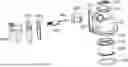
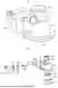


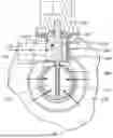
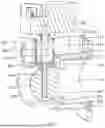
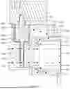
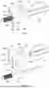


Sources:
- United States Patent and Trademark Office - verify current appl. status at the USPTO↗
Similar patent applications:
- » 20080078182
Premixing device, gas turbines comprising the premixing device, and methods of use - » 20110151389
AIR-GAS PREMIXING DEVICE IN A LOW-NOX GAS BURNER - » 20260185709
PREMIXER AND GAS DEVICE - » 20260078898
PREMIXER AND GAS DEVICE - » 20260185703
PREMIXER AND GAS DEVICE - » 20260185707
PREMIXER AND GAS DEVICE - » 20260185708
PREMIXER AND GAS DEVICE - » 20230272907
ANTI-BACKFLOW PREMIXING DEVICE AND FUEL GAS WATER HEATER - » 20160161114
Air-gas mixer device for premix burner equipment - » 20130284115
PREMIX COMBUSTION DEVICE OF GAS BURNER
Recent applications in this class:
- » 20260185703 2026-07-02
PREMIXER AND GAS DEVICE - » 20260185701 2026-07-02
NATURAL GAS CO-FIRING AMMONIA BURNER - » 20260117969 2026-04-30
BURNER BODY WITH VARIABLE GAS OUTLET AREA - » 20260078898 2026-03-19
PREMIXER AND GAS DEVICE - » 20260043542 2026-02-12
COMBUSTION MEMBRANE FOR A GAS BURNER - » 20250334265 2025-10-30
COMBUSTOR AND AMMONIA ENGINE SYSTEM - » 20250172288 2025-05-29
PREMIXING DEVICE AND COMBUSTION DEVICE INCLUDING THE SAME - » 20250172287 2025-05-29
CONTROLLING AN AIR FLOW RATE PROVIDED TO A BURNER BASED ON A CONCENTRATION OF GAS PROVIDED TO THE BURNER - » 20250084990 2025-03-13
BURNER COMPRISING A HEAT SHIELD AND METHOD OF OPERATING THE BURNER - » 20250052417 2025-02-13
INSTALLATION COMPRISING A PREMIXING BURNER
Recent applications for this Assignee:
- » 20260185709 2026-07-02
PREMIXER AND GAS DEVICE - » 20260185708 2026-07-02
PREMIXER AND GAS DEVICE - » 20260185707 2026-07-02
PREMIXER AND GAS DEVICE - » 20260185703 2026-07-02
PREMIXER AND GAS DEVICE - » 20260118065 2026-04-30
HEAT EXCHANGER AND GAS WATER HEATER - » 20260092651 2026-04-02
VALVE DEVICE AND GAS WATER HEATER - » 20260043583 2026-02-12
WATER TANK ASSEMBLY AND GAS WATER HEATER - » 20260036298 2026-02-05
BURNER HEAD, FIRE GRATE AND GAS DEVICE - » 20260002702 2026-01-01
MAGNESIUM ROD ASSEMBLY AND WATER HEATER - » 20260002700 2026-01-01
TANK MOUNTING STRUCTURE FOR WATER HEATER AND WATER HEATER