PREMIXER AND GAS DEVICE
US20260185708A1
2026-07-02
19/433,572
2025-12-26
Smart Summary: A premixer is designed to mix gas effectively before it is used. It has a body that contains a channel for the gas to flow through. Inside this channel, there is a gas distributor with multiple holes that release gas in different patterns. An adjustment shaft allows for control over the gas flow, and a gas regulator helps manage the gas pressure. The unique arrangement of the holes ensures that the gas is distributed evenly and efficiently. 🚀 TL;DR
Abstract:
A premixer includes a premixer body provided with a gas channel; a gas distributor at least partially provided in the gas channel; an adjustment shaft at least partially rotatably provided in the gas channel; and a gas regulator provided within the gas channel and located at the adjustment shaft. The gas distributor is provided with a first gas distribution hole, a second gas distribution hole, a third gas distribution hole, and a fourth gas distribution hole, each communicating with the gas channel, the first gas distribution hole and the second gas distribution hole are spaced apart, the third gas distribution hole and the fourth gas distribution hole are spaced apart, and a pattern formed by the first gas distribution hole is non-congruent with a pattern formed by the third gas distribution hole.
Inventors:
- Yu LIN 8 🇨🇳 Foshan, China
- Dingrui ZHANG 6 🇨🇳 Foshan, China
- Wei Fan 6 🇨🇳 Foshan, China
- Liuyang XIONG 4 🇨🇳 Foshan, China
Assignee:
- GUANGDONG MIDEA KITCHEN AND BATH APPLIANCES MFG. CO., LTD. 12 🇨🇳 Foshan, China
Applicant:
Interested in similar patents?
Get notified when new applications in this technology area are published.
Classification:
F23N1/02 » CPC main
Regulating fuel supply conjointly with air supply
F23N2235/16 » CPC further
Valves, nozzles or pumps; Fuel valves variable flow or proportional valves
Description
CROSS-REFERENCE TO RELATED APPLICATION
This application claims priority to Chinese Patent Application No. 202411999422.4, filed on December 31, 2024, the entire contents of which are incorporated herein by reference.
TECHNICAL FIELD
The present application relates to the technical field of gas heating, and in particular to a premixer and a gas device.
BACKGROUND
Gas devices such as gas water heaters, wall-mounted boilers, and gas stoves typically employ a completely premixed combustion method. Completely premixed combustion refers to a process in which air and gas are first completely mixed in a certain proportion to form a premixed gas-air, and the premixed gas-air is then ignited and burned in a burner.
The premixer is a crucial component in completely premixed gas device. The premixer mixes air and gas in a certain proportion to ensure that the optimal air-fuel ratio can be maintained during the combustion process. The existing premixers have a single function, cannot be applied to different gas sources, and have poor applicability.
SUMMARY
The main purpose of the present application is to provide a premixer and a gas device. The premixer has a simple structure and is convenient for adjusting the intake amount of the gas.
To achieve the above purpose, the premixer provided by the present application includes: a premixer body provided with a gas channel; and a gas regulator rotatably provided in the gas channel, the gas regulator is capable of rotating to adjust a gas flow area of the gas channel.
The present application further provides a premixer, including: a premixer body provided with a gas channel; a gas distributor at least partially provided in the gas channel; an adjustment shaft at least partially rotatably provided in the gas channel; and a gas regulator provided within the gas channel and located at the adjustment shaft.
The gas distributor is provided with a first gas distribution hole, a second gas distribution hole, a third gas distribution hole, and a fourth gas distribution hole, each communicating with the gas channel, the first gas distribution hole and the second gas distribution hole are spaced apart, the third gas distribution hole and the fourth gas distribution hole are spaced apart, and a pattern formed by the first gas distribution hole is non-congruent with a pattern formed by the third gas distribution hole.
The gas regulator is synchronously rotatable along with the adjustment shaft.
When the gas regulator rotates within a first angle range, the second gas distribution hole is completely unblocked. The gas regulator is capable of rotating to adjust a gas flow area of the first gas distribution hole to regulate an amount of gas flowing through the first gas distribution hole.
When the gas regulator rotates within a second angle range, the fourth gas distribution hole is completely unblocked. The gas regulator is capable of rotating to adjust a gas flow area of the third gas distribution hole to regulate an amount of gas flowing through the third gas distribution hole.
The present application further provides a premixer, including: a premixer body provided with a gas channel and a gas distribution chamber provided within the gas channel; an adjustment shaft rotatably passing through the gas distribution chamber; and a gas regulator provided within the gas channel and located at the adjustment shaft.
The gas distribution chamber has a cylindrical inner wall, and a side wall of the gas distribution chamber is provided with a gas inlet hole, a first gas distribution hole, a second gas distribution hole, a third gas distribution hole, and a fourth gas distribution hole, the first gas distribution hole and the second gas distribution hole are spaced apart, the third gas distribution hole and the fourth gas distribution hole are spaced apart, and a pattern formed by the first gas distribution hole is non-congruent with a pattern formed by the third gas distribution hole, and areas of the second gas distribution hole and the fourth gas distribution hole are different.
The gas regulator is synchronously rotatable along with the adjustment shaft and has an arc-shaped outer wall surface adapted to the inner wall of the gas distribution chamber.
When the gas regulator rotates within a first angle range, the second gas distribution hole is completely unblocked. The third gas distribution hole and the fourth gas distribution hole are blocked. The gas regulator is capable of rotating to adjust a gas flow area of the first gas distribution hole to regulate an amount of gas flowing through the first gas distribution hole.
When the gas regulator rotates within a second angle range, the first gas distribution hole and the second gas distribution hole are blocked. The fourth gas distribution hole is completely unblocked. The gas regulator is capable of rotating to adjust a gas flow area of the third gas distribution hole to regulate an amount of gas flowing through the third gas distribution hole.
The present application further provides a gas device, which includes the premixer as described above.
In the technical solution of the present application, the premixer includes a premixer body, a gas distributor, an adjustment shaft, and a gas regulator. The gas distributor is provided with a first gas distribution hole, a second gas distribution hole, a third gas distribution hole, and a fourth gas distribution hole, each communicating with a gas channel. The first gas distribution hole and the second gas distribution hole are spaced apart, and the third gas distribution hole and the fourth gas distribution hole are spaced apart. A pattern formed by the first gas distribution hole is non-congruent with a pattern formed by the third gas distribution hole, such that the patterns formed by the first gas distribution hole and the third gas distribution hole cannot completely overlap. The first gas distribution hole and the second gas distribution hole are used for the first gas to pass through, and the third gas distribution hole and the fourth gas distribution hole are used for the second gas to pass through. That is, the premixer of the present application is capable of allowing two different gases to pass through. When the gas regulator rotates within a first angle range, the premixer is adapted for mixing the first gas; when the gas regulator rotates within a second angle range, the premixer is adapted for mixing the second gas. In this way, switching between two different gases can be achieved.
When the gas regulator rotates within the first angle range and within the second angle range, the third gas distribution hole is completely unblocked in both cases, such that both the first gas and the second gas can flow through the third gas distribution hole. The third gas distribution hole functions as a shared gas passage for the first gas distribution hole and the second gas distribution hole. The area of the third gas distribution hole may be equal to a minimum gas flow area required when the second gas is at a minimum load, so that when the premixer mixes the second gas, the second gas only needs to flow through the third gas distribution hole to meet the gas amount required for the minimum load of the second gas. In this case, the second gas does not need to flow through the first gas distribution hole or the second gas distribution hole. This configuration facilitates control of the gas regulator and ensures that, when the second gas is at a minimum load, the third gas distribution hole can provide an accurate gas supply, thereby improving the reliability of the premixer.
Moreover, since the patterns formed by the first gas distribution hole and the second gas distribution hole cannot completely overlap, when the gas regulator adjusts an amount of gas flowing through the first gas distribution hole or adjusts an amount of gas flowing through the second gas distribution hole, not only can switching between two different gases be realized, but also a variation curve of a gas flow area of the first gas distribution hole adjusted by the gas regulator is not completely identical to a variation curve of a gas flow area of the second gas distribution hole adjusted by the gas regulator.
When the gas regulator rotates within the first angle range, the second gas distribution hole is completely unblocked, at which time the first gas can always pass through the second gas distribution hole. An area of the second gas distribution hole can be equal to a minimum gas flow area required when the first gas is at a minimum load state, such that, when the premixer mixes the first gas, the first gas only needs to flow along the second gas distribution hole to satisfy a gas demand required for the minimum load of the first gas. At this time, the first gas does not need to pass through the first gas distribution hole. This facilitates control of the gas regulator and ensures that, when the first gas is at the minimum load state, the second gas distribution hole can provide an accurate gas amount, thereby improving reliability of the premixer.
When the gas regulator rotates within the second angle range, the fourth gas distribution hole is completely unblocked, at which time the second gas can always pass through the fourth gas distribution hole. An area of the fourth gas distribution hole can be equal to a minimum gas flow area required when the second gas is at a minimum load state, such that, when the premixer mixes the second gas, the second gas only needs to flow along the fourth gas distribution hole to satisfy a gas demand required for the minimum load of the second gas. At this time, the second gas does not need to pass through the third gas distribution hole. This facilitates control of the gas regulator and ensures that, when the second gas is at the minimum load state, the fourth gas distribution hole can provide an accurate gas amount, thereby improving reliability of the premixer. Of course, an area of the second gas distribution hole may also be not limited, as long as it is capable of allowing the first gas to pass through; an area of the fourth gas distribution hole may also be not limited, as long as it is capable of allowing the second gas to pass through.
In addition, patterns formed by the first gas distribution hole and the third gas distribution hole cannot completely overlap. By adjusting, via the gas regulator, an amount of gas flowing through the first gas distribution hole or an amount of gas flowing through the third gas distribution hole, not only can switching use of two different gases be realized, but also a variation curve of a gas flow area of the first gas distribution hole adjusted by the gas regulator is not completely identical to a variation curve of a gas flow area of the third gas distribution hole adjusted by the gas regulator. This enables the premixer to accommodate different gas load requirements and increases the flexibility of the regulation performed by the gas regulator. Therefore, the premixer according to the present application can be used for switching between different gases to meet the needs of regions supplied with different gas sources. The premixer of the present application has excellent adaptability and can be widely applied.
BRIEF DESCRIPTION OF THE DRAWINGS
In order to explain the embodiments of the present application or the technical solutions in the existing technology more clearly, the accompanying drawings needed to be used in the description of the embodiments or the existing technology will be briefly introduced below. Obviously, the accompanying drawings in the following description are only some embodiments of the present application, other accompanying drawings can be obtained based on the provided accompanying drawings without exerting creative efforts for those skilled in the art.
FIG. 1 is a schematic structural diagram of a premixer according to an embodiment of the present application.
FIG. 2 is an exploded schematic diagram of the structure in FIG. 1.
FIG. 3 is a cross-sectional view of an air regulator and a gas regulator in FIG. 1 at a viewing angle of 180 degrees in a second angle range.
FIG. 4 is another cross-sectional view of the air regulator and the gas regulator in FIG. 1 at a viewing angle of 180 degrees in the second angle range.
FIG. 5 is a schematic structural diagram of the structure in FIG. 4 from another perspective.
FIG. 6 is a cross-sectional view of the air regulator and the gas regulator in FIG. 1 at a viewing angle of 270 degrees in the second angle range.
FIG. 7 is another cross-sectional view of the air regulator and the gas regulator in FIG. 1 at a viewing angle of 270 degrees in the second angle range.
FIG. 8 is a schematic structural diagram of the structure in FIG. 7 from another perspective.
FIG. 9 is a partial structural schematic diagram of a premixer according to an embodiment of the present application.
FIG. 10 is an exploded schematic diagram of the structure in FIG. 9.
FIG. 11 is a schematic structural diagram of a gas distributor in FIG. 10.
FIG. 12 is a schematic structural diagram of a partial structure in FIG. 10.
FIG. 13 is a schematic structural diagram of the structure in FIG. 12 from another perspective.
FIG. 14 is a schematic diagram of a first notch and a second notch of a first air supply notch in FIG. 13.
FIG. 15 is a schematic structural diagram of the structure in FIG. 13 from another perspective.
FIG. 16 is a schematic diagram of a third notch and a fourth notch of a second air supply notch in FIG. 15.
FIG. 17 is a schematic structural diagram of a venturi tube in FIG. 2.
FIG. 18 is a cross-sectional view of the structure in FIG. 17.
DESCRIPTION OF REFERENCE SIGNS
10, premixer;
100, premixer body; 110, gas channel; 111, gas homogenizing flow chamber; 112, corner; 120, air channel; 130, gas-air mixed channel; 140, base; 150, cover plate; 160, regulator; 170, air regulator;
200, gas distributor; 201, first side wall; 202, second side wall; 203, third side wall; 204, fourth side wall; 210, first gas distribution hole; 220, second gas distribution hole; 230, third gas distribution hole; 240, fourth gas distribution hole; 250, gas distribution chamber; 260, gas inlet hole; 270, first installation hole; 280, second installation hole;
300, adjustment shaft;
400, gas regulator; 410, first gas regulating part; 420, second gas regulating part; 430, first gas supply notch; 431, first notch; 432, second notch; 440, second gas supply notch; 441, third notch; 442, fourth notch; 450, first gas shield; 460, second gas shield;
500, venturi tube; 510, venturi channel; 520, air inlet; 530, gas injection inlet; 540, gas-air mixed outlet; 550, first pipe section; 551, tapered section; 552, transition section; 560, second pipe section; 570, connection portion;
600, first sealer;
700, second sealer.
The present application will be further explained in conjunction with embodiments and with reference to the accompanying drawings.
DETAILED DESCRIPTION OF THE EMBODIMENTS
The technical solutions in the embodiments according to the present application will be clearly and completely described below in conjunction with the accompanying drawings in the embodiments according to the present application, and it is clear that the described embodiments are only a part of the embodiments according to the present application, and not all of the embodiments. Based on the embodiments in the present application, all other embodiments obtained by those skilled in the art without making creative labor fall within the scope of the present application.
It should be noted that if there are directional instructions (such as up, down, left, right, front, back or the like) involved in the embodiments of the present application, the directional indications are only used to explain the relative positional relationship, movement and so on between various components in a specific posture (as shown in the accompanying drawings). If the specific posture changes, the directional indication will also change accordingly.
In addition, if there are descriptions involving “first”, “second” or the like, the descriptions of “first”, “second” or the like are only for descriptive purposes and cannot be understood as indicating or implying the relative importance or implicitly indicating the quantity of the technical features indicated. Therefore, features defined as “first” and “second” may explicitly or implicitly include at least one of these features. In addition, the meaning of “and/or” appearing in the entire text includes three parallel solutions, taking “A and/or B” as an example, it includes solution A, or solution B, or a solution that satisfies both A and B at the same time. In addition, the technical solutions of various embodiments can be combined with each other, but it is based on that those skilled in the art can realize. When the combination of technical solutions is contradictory or cannot be realized, it should be considered that such combination of technical solutions does not exist and is not within the protection scope claimed by the present application.
Gas appliances such as gas water heaters, wall-hung boilers, and gas stoves typically employ a fully premixed combustion method. Fully premixed combustion refers to a process in which air and gas are first fully mixed in a certain proportion to form a premixed gas-air, and this premixed gas-air is then ignited and burned in a burner.
The premixer is a crucial component in fully premixed gas device. The premixer ensures that the optimal air-fuel ratio can be maintained during the combustion process by mixing air and gas in a certain proportion. The existing premixers have a single function, cannot be applied to different gas sources, and have poor applicability.
Based on this, the present application provides a premixer and a gas device including the premixer. The premixer has good applicability and can be used for switching between different gas sources. The premixer can be applied to gas devices such as gas water heaters, wall-hung boilers, and gas stoves. The gas device may further include a burner and a fan. After air and gas are mixed into premixed gas-air in the premixer, the premixed air enters the burner under the action of the fan and flows out of the burner through the burner’s fire hole to achieve ignition and combustion. The structure of the premixer of the present application will be described below in the form of an embodiment.
The thick solid arrows in the drawings indicate the flow direction of air; the thick dashed arrows indicate the flow direction of gas; and the thick double-dash arrows indicate the flow direction of the mixed gas after the air and gas are mixed.
As shown in FIG. 1 to FIG. 8, in an embodiment of the present application, the premixer 10 includes a premixer body 100, a gas distributor 200, an adjustment shaft 300, and a gas regulator 400. The premixer body 100 has a gas channel 110. The gas distributor 200 is at least partially provided within the gas channel 110. The gas distributor 200 is provided with a first gas distribution hole 210, a second gas distribution hole 220, a third gas distribution hole 230, and a fourth gas distribution hole 240, which are respectively in communication with the gas channel 110. The first gas distribution hole 210 and the second gas distribution hole 220 are spaced apart from one another, and the third gas distribution hole 230 and the fourth gas distribution hole 240 are spaced apart from one another. A pattern formed by the first gas distribution hole 210 and a pattern formed by the third gas distribution hole 230 are non-congruent patterns. The adjustment shaft 300 is at least partially rotatably provided within the gas channel 110. The gas regulator 400 is provided within the gas channel 110 and located at the adjustment shaft 300, and the gas regulator 400 can rotate synchronously with the adjustment shaft 300. When the gas regulator 400 rotates within a first angle range, the second gas distribution hole 220 is completely unblocked, and the gas regulator 400 is capable of rotating to adjust the gas flow area of the first gas distribution hole 210 to regulate the amount of gas flowing through the first gas distribution hole 210. When the gas regulator 400 rotates within a second angle range, the fourth gas distribution hole 240 is completely unblocked, and the gas regulator 400 is capable of rotating to adjust the gas flow area of the third gas distribution hole 230 to regulate the amount of gas flowing through the third gas distribution hole 230.
It can be understood that the gas channel 110 is used for gas inflow, and the type of gas is not limited, for example but not limited to: natural gas, liquefied petroleum gas, biogas, and synthesis gas, etc. The size and position of the gas channel 110 are not limited, and are specifically provided according to needs.
The shape of the gas distributor 200 is not limited and may be plate-shaped, cylindrical, or other shapes. The gas distributor 200 may be fixed within the gas channel 110 to form an integral structure with the inner wall of the channel, or the gas distributor 200 may be detachably provided within the gas channel 110. In an embodiment, the premixer body 100 includes a base 140, and the base 140 has the gas channel 110. The gas distributor 200 and the base 140 may be detachably arranged, or the gas distributor 200 and the base 140 may be formed as an integral structure.
The gas distributor 200 is provided with a first gas distribution hole 210, a second gas distribution hole 220, a third gas distribution hole 230, and a fourth gas distribution hole 240, which can allow at least two different types of gas to pass through. The first gas distribution hole 210 and the second gas distribution hole 220 are spaced apart from one another, and the third gas distribution hole 230 and the fourth gas distribution hole 240 are spaced apart from one another. Of course, the first gas distribution hole 210 may also be spaced apart from the third gas distribution hole 230, which is not specifically limited.
In the present application, the first gas distribution hole 210 and the second gas distribution hole 220 may be used for supplying a first gas, and the third gas distribution hole 230 and the fourth gas distribution hole 240 may be used for supplying a second gas. That is, the first gas distribution hole 210, the second gas distribution hole 220, the third gas distribution hole 230, and the fourth gas distribution hole 240 can allow two different types of gas to pass through.
For the convenience of description below, one of the two different types of gas is referred to as the first gas, and the other is referred to as the second gas. The types of the first gas and the second gas are not limited. For example, but not limited to, the first gas distribution hole 210 and the second gas distribution hole 220 may be used for supplying natural gas, and the third gas distribution hole 230 and the fourth gas distribution hole 240 may be used for supplying liquefied petroleum gas; or the first gas distribution hole 210 and the second gas distribution hole 220 may be used for supplying liquefied petroleum gas, and the third gas distribution hole 230 and the fourth gas distribution hole 240 may be used for supplying natural gas. The specific configuration can be determined as needed.
The quantities of the first gas distribution holes 210, the second gas distribution holes 220, the third gas distribution holes 230, and the fourth gas distribution holes 240 may each be one or more, and are not specifically limited herein. The shapes and sizes of the first gas distribution hole 210 and the third gas distribution hole 230 are not limited, as long as the pattern formed by the first gas distribution hole 210 and the pattern formed by the third gas distribution hole 230 are non-congruent, that is, the patterns formed by the first gas distribution hole 210 and the third gas distribution hole 230 cannot completely overlap. By rotating the gas regulator 400 within the first angle range to adjust the amount of gas flowing through the first gas distribution hole 210, and by rotating the gas regulator 400 within the second angle range to adjust the amount of gas flowing through the third gas distribution hole 230, the switching use of two different gases can be realized. In this way, the variation curve of the gas flow area of the first gas distribution hole 210 adjusted by the gas regulator 400 is not completely identical to the variation curve of the gas flow area of the third gas distribution hole 230, thereby adapting to different gases.
The adjustment shaft 300 may be driven by the regulator 160. The regulator 160 drives the adjustment shaft 300 to rotate, thereby driving the gas regulator 400 to rotate synchronously. The regulator 160 may be a motor.
It should be noted that when the gas regulator 400 rotates within the first angle range, the first gas distribution hole 210 can be blocked or can be completely or partially unblocked, and the second gas distribution hole 220 is completely unblocked. At this time, the first gas can always pass through the second gas distribution hole 220 to be mixed with air. When the gas regulator 400 rotates within the second angle range, the third gas distribution hole 230 can be blocked or can be completely or partially unblocked, and the fourth gas distribution hole 240 is completely unblocked. At this time, the second gas can always pass through the fourth gas distribution hole 240 to be mixed with air. That is, the gas regulator 400 is capable of rotating to perform blocking or unblocking of the first gas distribution hole 210 and blocking or unblocking of the third gas distribution hole 230.
In the present application, the gas regulator 400 blocking the first gas distribution hole 210 means that the gas regulator 400 obstructs, covers, or shields the first gas distribution hole 210 so as to prevent gas from passing through the first gas distribution hole 210 as much as possible. The gas regulator 400 may be in contact with the wall surface of the gas distributor 200 at the first gas distribution hole 210, or a small gap may be provided between the gas regulator 400 and the wall surface of the gas distributor 200 at the first gas distribution hole 210 to allow assembly tolerance and part machining error, thereby permitting a small amount of gas to pass through. The amount of gas passing through the gap does not affect the use of the premixer 10. That is, the term “blocking” in the present application has a meaning different from that of “sealing.” Similarly, the gas regulator 400 blocking the third gas distribution hole 230 means that the gas regulator 400 obstructs, covers, or shields the third gas distribution hole 230 so as to prevent gas from passing through the third gas distribution hole 230 as much as possible.
The gas regulator 400 unblocking the first gas distribution hole 210 means that the previously blocked first gas distribution hole 210 is unblocked or cleared, allowing gas to flow through the first gas distribution hole 210. Similarly, the gas regulator 400 unblocking the third gas distribution hole 230 means that the previously blocked third gas distribution hole 230 is unblocked or cleared, allowing gas to flow through the third gas distribution hole 230.
The shapes and sizes of the second gas distribution hole 220 and the fourth gas distribution hole 240 are not limited. When the gas regulator 400 rotates within the first angle range, the second gas distribution hole 220 is completely unblocked. At this time, the first gas can always pass through the second gas distribution hole 220, and the area of the second gas distribution hole 220 can be equal to the minimum gas flow area required when the first gas is in a minimum load state, such that when the premixer 10 mixes the first gas, the first gas only needs to flow along the second gas distribution hole 220 to meet the required amount of gas for the minimum load of the first gas. At this time, the first gas does not need to pass through the first gas distribution hole 210, which facilitates control of the gas regulator 400 and ensures that the second gas distribution hole 220 can provide an accurate amount of gas when the first gas is in the minimum load state, thereby improving the reliability of the premixer 10. When the gas regulator 400 rotates within the second angle range, the fourth gas distribution hole 240 is completely unblocked. At this time, the second gas can always pass through the fourth gas distribution hole 240, and the area of the fourth gas distribution hole 240 can be equal to the minimum gas flow area required when the second gas is in a minimum load state, such that when the premixer 10 mixes the second gas, the second gas only needs to flow along the fourth gas distribution hole 240 to meet the required amount of gas for the minimum load of the second gas. At this time, the second gas does not need to pass through the third gas distribution hole 230, which facilitates control of the gas regulator 400 and ensures that the fourth gas distribution hole 240 can provide an accurate amount of gas when the second gas is in the minimum load state, thereby improving the reliability of the premixer 10.
The specific structure and shape of the gas regulator 400 are not limited and may be block-shaped, plate-shaped, or other forms, as long as the gas regulator 400 can adjust the gas flow areas of the first gas distribution hole 210 and the third gas distribution hole 230, that is, it can adjust the gas intake amount of the first gas distribution hole 210 and the gas intake amount of the third gas distribution hole 230.
In an embodiment, the quantity of gas regulators 400 may be one, and the gas flow through the first gas distribution hole 210 or the gas flow through the third gas distribution hole 230 can be adjusted by a single gas regulator 400.
In another embodiment, the gas regulator 400 includes at least two regulating parts, and the gas flow through the first gas distribution hole 210 or the gas flow through the third gas distribution hole 230 can be adjusted by at least two regulating parts.
The specific numerical ranges of the first angle range and the second angle range are not limited. The first angle range and the second angle range may partially overlap, or they may have no overlapping range. For example, but not limited to, the first angle range may be 0 to 45 degrees, or 0 to 60 degrees, or 0 to 90 degrees, or 0 to 180 degrees, or 0 to 270 degrees, etc.; the second angle range may be 60 to 180 degrees, or 90 to 180 degrees, or 90 to 270 degrees, or 90 to 360 degrees, or 180 to 270 degrees, or 180 to 360 degrees, or 270 to 360 degrees, etc.
When the gas regulator 400 rotates within the first angle range, it indicates that the premixer 10 is suitable for mixing the first gas at this time. The first gas can flow through the second gas distribution hole 220, and as the gas regulator 400 completely or partially unblocks the first gas distribution hole 210, the first gas can also flow through the first gas distribution hole 210. With such an arrangement, the amount of the first gas flowing into the gas channel 110 can be adjusted to ensure that a portion of the first gas always passes through the gas channel 110 for mixing, and the required gas amount for the minimum load of the first gas can be satisfied by the second gas distribution hole 220.
When the gas regulator 400 rotates within the second angle range, it indicates that the premixer 10 is suitable for mixing the second gas at this time. The second gas can flow through the fourth gas distribution hole 240, and as the gas regulator 400 completely or partially unblocks the third gas distribution hole 230, the second gas can also flow through the third gas distribution hole 230. With such an arrangement, the amount of the second gas flowing into the gas channel 110 can be adjusted to ensure that a portion of the second gas always passes through the gas channel 110 for mixing, and the fourth gas distribution hole 240 can meet the required gas amount for the minimum load of the second gas.
In the technical solution of the present application, the premixer 10 includes a premixer body 100, a gas distributor 200, an adjustment shaft 300, and a gas regulator 400. The gas distributor 200 is provided with a first gas distribution hole 210, a second gas distribution hole 220, a third gas distribution hole 230, and a fourth gas distribution hole 240, which are respectively in communication with the gas channel 110. The first gas distribution hole 210 and the second gas distribution hole 220 are arranged at intervals, and the third gas distribution hole 230 and the fourth gas distribution hole 240 are arranged at intervals. A pattern formed by the first gas distribution hole 210 and a pattern formed by the third gas distribution hole 230 are non-congruent patterns, such that the patterns formed by the first gas distribution hole 210 and the third gas distribution hole 230 cannot completely overlap. The first gas distribution hole 210 and the second gas distribution hole 220 are used for supplying the first gas, and the third gas distribution hole 230 and the fourth gas distribution hole 240 are used for supplying the second gas. That is, the premixer 10 in the present application can allow two different types of gas to pass through. When the gas regulator 400 rotates within the first angle range, the premixer 10 is suitable for mixing the first gas; when the gas regulator 400 rotates within the second angle range, the premixer 10 is suitable for mixing the second gas. In this way, the switching use of two different gases can be realized.
When the gas regulator 400 rotates within the first angle range, the second gas distribution hole 220 is completely unblocked. At this time, the first gas can always pass through the second gas distribution hole 220, and the area of the second gas distribution hole 220 can be equal to the minimum gas flow area required when the first gas is in a minimum load state, such that when the premixer 10 mixes the first gas, the first gas only needs to flow along the second gas distribution hole 220 to meet the required amount of gas for the minimum load of the first gas. At this time, the first gas does not need to pass through the first gas distribution hole 210, which facilitates control of the gas regulator 400 and ensures that the second gas distribution hole 220 can provide an accurate amount of gas when the first gas is in the minimum load state, thereby improving the reliability of the premixer 10. When the gas regulator 400 rotates within the second angle range, the fourth gas distribution hole 240 is completely unblocked. At this time, the second gas can always pass through the fourth gas distribution hole 240, and the area of the fourth gas distribution hole 240 can be equal to the minimum gas flow area required when the second gas is in a minimum load state, such that when the premixer 10 mixes the second gas, the second gas only needs to flow along the fourth gas distribution hole 240 to meet the required amount of gas for the minimum load of the second gas. At this time, the second gas does not need to pass through the third gas distribution hole 230, which facilitates control of the gas regulator 400 and ensures that the fourth gas distribution hole 240 can provide an accurate amount of gas when the second gas is in the minimum load state, thereby improving the reliability of the premixer 10. Of course, the area of the second gas distribution hole 220 may also not be limited, as long as it can allow the first gas to pass through; likewise, the area of the fourth gas distribution hole 240 may not be limited, as long as it can allow the second gas to pass through.
In addition, the patterns formed by the first gas distribution hole 210 and the third gas distribution hole 230 cannot completely overlap. By adjusting the gas flow through the first gas distribution hole 210 or adjusting the gas flow through the third gas distribution hole 230 via the gas regulator 400, not only can the switching use of two different gases be realized, but also the variation curve of the gas flow area of the first gas distribution hole 210 adjusted by the gas regulator 400 is not completely identical to the variation curve of the gas flow area of the third gas distribution hole 230, so as to adapt to the requirements of different gas loads. This increases the flexibility of adjustment by the gas regulator 400, allowing the premixer 10 of the present application to switch between different gases to meet the usage requirements in regions with different gas sources. The premixer 10 of the present application thus has good applicability and can be widely used.
In an embodiment, the first gas distribution hole 210 and the second gas distribution hole 220 are used for supplying the first gas, and the third gas distribution hole 230 and the fourth gas distribution hole 240 are used for supplying the second gas. A minimum gas flow area required when the first gas is in a minimum load state is S1, and a minimum gas flow area required when the second gas is in a minimum load state is S2. An area of the second gas distribution hole 220 is S1, and an area of the fourth gas distribution hole 240 is S2. With such an arrangement, the area of the second gas distribution hole 220 is equal to the minimum gas flow area required when the first gas is in a minimum load state, that is, the second gas distribution hole 220 can meet the required amount of gas for mixing the first gas through the premixer 10 when the first gas is in a minimum load state. In addition, the area of the fourth gas distribution hole 240 is equal to the minimum gas flow area required when the second gas is in a minimum load state, that is, the fourth gas distribution hole 240 can meet the required amount of gas for mixing the second gas through the premixer 10 when the second gas is in a minimum load state. The types of the first gas and the second gas are not limited and can be set according to the types of gases used in different regions. The values of S1 and S2 can be determined based on the corresponding types of gases, that is, the values of S1 and S2 corresponding to the types of gases are known when the product is designed, and the premixer 10 is manufactured according to the determined values of S1 and S2 based on the types of gases used in different regions. The types of the first gas and the second gas include but are not limited to natural gas, liquefied petroleum gas, biogas, and synthetic gas.
In an embodiment, when the gas regulator 400 rotates within the first angle range, the third gas distribution hole 230 and the fourth gas distribution hole 240 are blocked; when the gas regulator 400 rotates within the second angle range, the first gas distribution hole 210 and the second gas distribution hole 220 are blocked.
It can be understood that when the gas regulator 400 rotates within the first angle range, since the third gas distribution hole 230 and the fourth gas distribution hole 240 are blocked, the first gas cannot pass through the third gas distribution hole 230 and the fourth gas distribution hole 240, and the first gas can only pass through the first gas distribution hole 210 and the second gas distribution hole 220. In addition, the area of the second gas distribution hole 220 can be equal to the minimum gas flow area required when the first gas is in a minimum load state, such that the second gas distribution hole 220 can meet the required amount of gas for the minimum load of the first gas. At this time, the first gas does not need to pass through the first gas distribution hole 210, which helps ensure that the second gas distribution hole 220 can provide an accurate amount of gas when the first gas is in the minimum load state, thereby improving the reliability of the premixer 10.
When the gas regulator 400 rotates within the second angle range, since the first gas distribution hole 210 and the second gas distribution hole 220 are blocked, the second gas cannot pass through the first gas distribution hole 210 and the second gas distribution hole 220, and the second gas can only pass through the third gas distribution hole 230 and the fourth gas distribution hole 240. In addition, the area of the fourth gas distribution hole 240 can be equal to the minimum gas flow area required when the second gas is in a minimum load state, such that the fourth gas distribution hole 240 can meet the required amount of gas for the minimum load of the second gas. At this time, the second gas does not need to pass through the third gas distribution hole 230, which helps ensure that the fourth gas distribution hole 240 can provide an accurate amount of gas when the second gas is in the minimum load state, thereby improving the reliability of the premixer 10.
In an embodiment, the areas of the second gas distribution hole 220 and the fourth gas distribution hole 240 are different. It can be understood that the minimum gas flow area required for different gases in the minimum load state is different. In this solution, by defining the areas of the second gas distribution hole 220 and the fourth gas distribution hole 240 to be different, the premixer 10 can meet the situations in which different types of gases require different minimum gas flow areas in the minimum load state, thereby enabling the premixer 10 to switch between different gases to meet the usage requirements in regions with different gas sources and improving the applicability of the premixer 10.
In an embodiment, the first angle range and the second angle range have no overlapping range. For example, the first angle range may be 0 to 90 degrees and the second angle range may be 180 to 270 degrees; or the first angle range may be 90 to 180 degrees and the second angle range may be 270 to 360 degrees. The specific ranges are not limited herein.
The relative positions of the first gas distribution hole 210, the second gas distribution hole 220, the third gas distribution hole 230, and the fourth gas distribution hole 240 are not limited. In an embodiment, the first gas distribution hole 210, the second gas distribution hole 220, the third gas distribution hole 230, and the fourth gas distribution hole 240 are arranged at intervals from each other on the gas distributor 200, so that the first gas distribution hole 210, the second gas distribution hole 220, the third gas distribution hole 230, and the fourth gas distribution hole 240 do not interfere with each other, thereby facilitating the unblocking or blocking operation by the gas regulator 400.
In an embodiment, the area of the first gas distribution hole 210 is greater than the area of the third gas distribution hole 230, the area of the second gas distribution hole 220 is greater than the area of the fourth gas distribution hole 240, the second gas distribution hole 220 is provided adjacent to the first gas distribution hole 210, and the fourth gas distribution hole 240 is provided adjacent to the third gas distribution hole 230.
With such an arrangement, since both the first gas distribution hole 210 and the second gas distribution hole 220 are used for the passage of the first gas, the second gas distribution hole 220 is provided adjacent to the first gas distribution hole 210. When the premixer 10 mixes the first gas, it is convenient for the gas regulator 400 to synchronously unblock the first gas distribution hole 210 and the second gas distribution hole 220, which is beneficial for improving structural compactness. Similarly, since both the third gas distribution hole 230 and the fourth gas distribution hole 240 are used for the passage of the second gas, the fourth gas distribution hole 240 is provided adjacent to the third gas distribution hole 230. When the premixer 10 mixes the second gas, it is convenient for the gas regulator 400 to synchronously unblock the third gas distribution hole 230 and the fourth gas distribution hole 240, which is beneficial for improving structural compactness.
In an embodiment, the first gas distribution hole 210 and the second gas distribution hole 220 are circumferentially spaced along a rotation direction of the gas regulator 400; the third gas distribution hole 230 and the fourth gas distribution hole 240 are circumferentially spaced along the rotation direction of the gas regulator 400, and the first gas distribution hole 210 and the second gas distribution hole 220 are spaced apart along an axial direction of the adjustment shaft 300. With such an arrangement, it is convenient for the gas regulator 400 to unblock or block the first gas distribution hole 210 and the second gas distribution hole 220 during rotation. The first gas distribution hole 210 and the second gas distribution hole 220 are used for the passage of two different gases, thereby facilitating the switching use of two different gases.
In an embodiment, the first gas distribution hole 210, the second gas distribution hole 220, the third gas distribution hole 230, and the fourth gas distribution hole 240 are circumferentially spaced along a rotation direction of the gas regulator 400 on the gas distributor 200. Such an arrangement facilitates the gas regulator 400 in unblocking or blocking the first gas distribution hole 210, the second gas distribution hole 220, the third gas distribution hole 230, and the fourth gas distribution hole 240. The quantity of gas regulators 400 may be one or more. Even when only one gas regulator 400 is provided in the premixer 10, it can still realize the switching use of two different gases to meet the requirements of different gas sources in different regions. The premixer 10 of the present application therefore has good applicability and can be widely used.
In an embodiment, the quantity of gas regulators 400 is one, which helps simplify the structure of the premixer 10.
In an embodiment, the gas regulator 400 includes a sector-shaped shielding plate or a sector-shaped shielding block. By providing a sector-shaped shielding plate or shielding block, the part structure can be simplified, and the manufacturing difficulty can be reduced.
In an embodiment, the quantity of the first gas distribution holes 210 is one or more; the quantity of the second gas distribution holes 220 is one or more; the quantity of the third gas distribution holes 230 is one or more; and the quantity of the fourth gas distribution holes 240 is one or more. That is, the numbers of the first gas distribution holes 210, the second gas distribution holes 220, the third gas distribution holes 230, and the fourth gas distribution holes 240 are not limited and can be set as needed.
In an embodiment, the quantity of the first gas distribution holes 210 is multiple, and the areas of any two of the first gas distribution holes 210 are identical, or the areas of at least two of the first gas distribution holes 210 are different; the quantity of the second gas distribution holes 220 is multiple, and the areas of any two of the second gas distribution holes 220 are identical, or the areas of at least two of the second gas distribution holes 220 are different; the quantity of the third gas distribution holes 230 is multiple, and the areas of any two of the third gas distribution holes 230 are identical, or the areas of at least two of the third gas distribution holes 230 are different; and the quantity of the fourth gas distribution holes 240 is multiple, and the areas of any two of the fourth gas distribution holes 240 are identical, or the areas of at least two of the fourth gas distribution holes 240 are different. With such an arrangement, the areas of multiple first gas distribution holes 210 may be at least partially identical or at least partially different; the areas of multiple second gas distribution holes 220 may be at least partially identical or at least partially different; the areas of multiple third gas distribution holes 230 may be at least partially identical or at least partially different; and the areas of multiple fourth gas distribution holes 240 may be at least partially identical or at least partially different, which are not particularly limited herein.
In an embodiment, the adjustment shaft 300 is provided outside the first gas distribution hole 210, the second gas distribution hole 220, the third gas distribution hole 230, and the fourth gas distribution hole 240, that is, the adjustment shaft 300 does not block the gas flowing through the first gas distribution hole 210, the second gas distribution hole 220, the third gas distribution hole 230, and the fourth gas distribution hole 240. This allows the gas to smoothly flow through the first gas distribution hole 210, the second gas distribution hole 220, the third gas distribution hole 230, and the fourth gas distribution hole 240 into the gas-air mixed channel 130 of the premixer body 100.
As shown in FIG. 2 to FIG. 8, in an embodiment, the gas regulator 400 includes a first gas regulating part 410 and a second gas regulating part 420 provided at the adjustment shaft 300. The first gas regulating part 410 and the second gas regulating part 420 can rotate synchronously with the adjustment shaft 300. When the adjustment shaft 300 rotates within the first angle range, the first gas regulating part 410 is capable of rotating to adjust a gas flow area of the first gas distribution hole 210, completely unblocks the second gas distribution hole 220, and the second gas regulating part 420 blocks the third gas distribution hole 230 and the fourth gas distribution hole 240. When the adjustment shaft 300 rotates within the second angle range, the first gas regulating part 410 blocks the first gas distribution hole 210 and the second gas distribution hole 220, the second gas regulating part 420 is capable of rotating to adjust a gas flow area of the third gas distribution hole 230, and completely unblocks the fourth gas distribution hole 240.
It should be understood that, the shape and size of the first gas regulating part 410 and the second gas regulating part 420 are not limited. Through the first gas regulating part 410, a gas flow area of the first gas distribution hole 210 is adjusted, and the first gas regulating part 410 opens or blocks the second gas distribution hole 220. Through the second gas regulating part 420, a gas flow area of the third gas distribution hole 230 is adjusted, and the second gas regulating part 420 opens or blocks the fourth gas distribution hole 240. The first gas regulating part 410 and the second gas regulating part 420 rotate synchronously with the adjustment shaft 300. In this way, by rotating a single adjustment shaft 300, both the first gas regulating part 410 and the second gas regulating part 420 can be driven to rotate synchronously to enable the switching between two different gases. The switching method between different gases is simple, which helps simplify the structure of the premixer 10 and improve its applicability.
In an embodiment, the first gas regulating part 410 and the second gas regulating part 420 are provided along an axial direction of the adjustment shaft 300; along a gas outlet direction of the gas channel 110, the first gas regulating part 410 is provided upstream of the first gas distribution hole 210 and the second gas distribution hole 220, and the second gas regulating part 420 is provided upstream of the third gas distribution hole 230 and the fourth gas distribution hole 240. With such an arrangement, when the first gas regulating part 410 and the second gas regulating part 420 rotate together with the adjustment shaft 300, they do not interfere with one another. The first gas regulating part 410 does not affect the gas flowing out from outlet ends of the first gas distribution hole 210 and the second gas distribution hole 220, and the second gas regulating part 420 does not affect the gas flowing out from outlet ends of the third gas distribution hole 230 and the fourth gas distribution hole 240, which helps improve the smoothness of the gas flow.
As shown in FIG. 6 to FIG. 10, in an embodiment, the first gas regulating part 410 and the second gas regulating part 420 are provided along an axial direction of the adjustment shaft 300; the first gas distribution hole 210 and the second gas distribution hole 220 are circumferentially spaced along a rotation direction of the first gas regulating part 410 on the gas distributor 200; and the third gas distribution hole 230 and the fourth gas distribution hole 240 are circumferentially spaced along a rotation direction of the second gas regulating part 420 on the gas distributor 200.
With such an arrangement, when the first gas regulating part 410 and the second gas regulating part 420 rotate together with the adjustment shaft 300, they do not interfere with one another, and the first gas regulating part 410 is provided opposite to the first gas distribution hole 210 and the second gas distribution hole 220, and the second gas regulating part 420 is provided opposite to the third gas distribution hole 230 and the fourth gas distribution hole 240, thereby facilitating the switching use of two different gases by the first gas regulating part 410 and the second gas regulating part 420, and the internal structural arrangement of the premixer 10 is reasonable.
As shown in FIG. 3 to FIG. 11, in an embodiment, the gas distributor 200 includes a gas distribution chamber 250 and gas inlet holes 260, first gas distribution holes 210, second gas distribution holes 220, third gas distribution holes 230, and fourth gas distribution holes 240, all of which are respectively in communication with the gas distribution chamber 250. The gas inlet hole 260 is used for communication with an external gas source. The first gas regulating part 410 is rotatably provided within the gas distribution chamber 250 to unblock or block the first gas distribution hole 210 and/or the second gas distribution hole 220; the second gas regulating part 420 is rotatably provided within the gas distribution chamber 250 to unblock or block the third gas distribution hole 230 and/or the fourth gas distribution hole 240.
It can be understood that the specific shape of the gas distribution chamber 250 is not limited, as long as the gas regulator 400 can be adapted to the gas distribution chamber 250. External gas can flow into the gas distribution chamber 250 through the gas inlet hole 260. The premixer body 100 further includes an air channel 120 and a gas-air mixed channel 130 communicating with the gas channel 110 and the air channel 120. The gas-air mixed channel 130 is used to premix the air and gas flowing therein.
The first gas regulating part 410 is rotatably provided within the gas distribution chamber 250. When the first gas regulating part 410 blocks the first gas distribution hole 210 and/or the second gas distribution hole 220, the gas regulator 400 is in close contact with or has a small gap with an inner chamber wall of the gas distribution chamber 250, so that gas in the gas distribution chamber 250 cannot flow out from the first gas distribution hole 210 and/or the second gas distribution hole 220. It should be noted that, when there is a small gap between the first gas regulating part 410 and the inner chamber wall of the gas distribution chamber 250 at the first gas distribution hole 210 and/or the second gas distribution hole 220, the small gap is provided for rotation of the first gas regulating part 410 within the gas distribution chamber 250 and for assembly and process tolerances, and an amount of gas flowing out through the small gap is extremely small or can be ignored.
Similarly, the second gas regulating part 420 is rotatably provided within the gas distribution chamber 250. When the second gas regulating part 420 blocks the third gas distribution hole 230 and/or the fourth gas distribution hole 240, the gas regulator 400 is in close contact with or has a small gap with an inner chamber wall of the gas distribution chamber 250, so that gas in the gas distribution chamber 250 cannot flow out from the third gas distribution hole 230 and/or the fourth gas distribution hole 240. It should be noted that, when there is a small gap between the second gas regulating part 420 and the inner chamber wall of the gas distribution chamber 250 at the third gas distribution hole 230 and/or the fourth gas distribution hole 240, the small gap is provided for rotation of the second gas regulating part 420 within the gas distribution chamber 250 and for assembly and process tolerances, and an amount of gas flowing out through the small gap is extremely small or can be ignored.
In the present solution, by providing the gas distribution chamber 250, the gas inlet hole 260, the first gas distribution hole 210, the second gas distribution hole 220, the third gas distribution hole 230, and the fourth gas distribution hole 240 on the gas distributor 200, and by allowing the first gas regulating part 410 and the second gas regulating part 420 to rotate within the gas distribution chamber 250, the switching use between two different gases can be realized. The regulating manner of this solution is simple and easy to implement, which helps simplify the structure of the premixer 10.
In an embodiment, the first gas distribution hole 210, the second gas distribution hole 220, the third gas distribution hole 230, and the fourth gas distribution hole 240 are all provided at a first side of the gas distributor 200. The gas inlet hole 260 is provided at a second side of the gas distributor 200, and the first side and the second side are provided adjacent to or opposite one another.
It can be understood that the gas inlet hole 260 and the first gas distribution hole 210, the second gas distribution hole 220, the third gas distribution hole 230, and the fourth gas distribution hole 240 are provided at different sides of the gas distributor 200, so that the gas flows into the gas distributor 200 from one side and is discharged from the other side. This arrangement helps improve the smoothness of gas flow.
In an embodiment, the first gas regulating part 410 and the second gas regulating part 420 are spaced apart along the axial direction of the adjustment shaft 300. In the projection along the axial direction of the gas inlet hole 260, the gas inlet hole 260 is at least partially provided between the first gas regulating part 410 and the second gas regulating part 420.
It can be understood that the first gas regulating part 410 is arranged correspondingly to the first gas distribution hole 210 and the second gas distribution hole 220, and the second gas regulating part 420 is arranged correspondingly to the third gas distribution hole 230 and the fourth gas distribution hole 240. In the projection along the axial direction of the gas inlet hole 260, the gas inlet hole 260 is at least partially provided between the first gas regulating part 410 and the second gas regulating part 420, so that the gas flowing into the gas distribution chamber 250 from the gas inlet hole 260 can flow in opposite directions and selectively flow through the first gas distribution hole 210 or the second gas distribution hole 220 along with rotations of the first gas regulating part 410 and the second gas regulating part 420. This configuration helps shorten the total flow path of the gas from the gas inlet hole 260 to the first gas distribution hole 210 and the second gas distribution hole 220, making the arrangement of the gas inlet hole 260, the first gas distribution hole 210, and the second gas distribution hole 220 on the gas distributor 200 more compact, thereby shortening the flow path of the gas in the gas distribution chamber 250 and improving the gas flow speed.
In an embodiment, the quantity of the gas inlet holes 260 may be one or more. That is, the quantity of the gas inlet holes 260 is not limited and can be set as needed.
In an embodiment, along the axial direction of the adjustment shaft 300, the gas inlet hole 260 is arranged in an offset manner relative to the first gas regulating part 410 and the second gas regulating part 420. With this arrangement, the first gas regulating part 410 and the second gas regulating part 420 do not block the gas inlet hole 260. Regardless of whether the first gas regulating part 410 and the second gas regulating part 420 rotate, the gas can flow from the gas inlet hole 260 into the gas distribution chamber 250, thereby facilitating smooth gas inflow into the gas distribution chamber 250.
As shown in FIG. 6 to FIG. 16, in an embodiment, the first gas regulating part 410 and the adjustment shaft 300 together form a first gas supply notch 430, or the first gas regulating part 410 is provided with a first gas supply notch 430; the second gas regulating part 420 and the adjustment shaft 300 together form a second gas supply notch 440, or the second gas regulating part 420 is provided with a second gas supply notch 440. When the adjustment shaft 300 rotates within the first angle range, an opening of the first gas supply notch 430 partially overlaps with the first gas distribution hole 210 or offsets with respect to the first gas distribution hole 210, and an opening of the first gas supply notch 430 partially overlaps with the second gas distribution hole 220; an opening of the second gas supply notch 440 is completely offset with respect to the third gas distribution hole 230 and the fourth gas distribution hole 240. When the adjustment shaft 300 rotates within the second angle range, an opening of the second gas supply notch 440 partially overlaps with the third gas distribution hole 230 or offsets with respect to the third gas distribution hole 230, and an opening of the second gas supply notch 440 partially overlaps with the fourth gas distribution hole 240; and an opening of the first gas supply notch 430 is completely offset with respect to the first gas distribution hole 210 and the second gas distribution hole 220.
It can be understood that the specific numerical ranges of the first angle range and the second angle range are not limited. The first angle range and the second angle range may partially overlap, or the first angle range and the second angle range may have no overlapping range.
When the first gas is in a minimum load state, the minimum gas flow area required is S1. For the first gas regulating part 410 and the second gas regulating part 420, 0 degrees may represent the preset initial position of the first gas regulating part 410 and the second gas regulating part 420. The preset initial position may be a position where the first gas regulating part 410 blocks the first gas distribution hole 210 and completely unblocks the second gas distribution hole 220. The second gas regulating part 420 blocks the third gas distribution hole 230 and the fourth gas distribution hole 240. At this time, an area of the second gas distribution hole 220 is S1, that is, the area of the second gas distribution hole 220 is equal to the minimum gas flow area required when the first gas is in the minimum load state. The specific shape and position of the opening of the first gas supply notch 430 are not limited.
Specifically, in this embodiment, the first angle range is 0 to 90 degrees.
When the first gas regulating part 410 and the second gas regulating part 420 are at the 0-degree position, the openings of the first gas supply notch 430 partially offsets with respect to the first gas distribution hole 210, and the openings of the first gas supply notch 430 partially overlaps with the second gas distribution hole 220. The openings of the second gas supply notch 440 partially offsets with respect to the third gas distribution hole 230 and the fourth gas distribution hole 240, such that an area of the second gas distribution hole 220 is equal to the minimum gas flow area S1 required when the first gas is in a minimum load state. At this time, the premixer 10 mixes the minimum amount of the first gas.
When the first gas regulating part 410 and the second gas regulating part 420 are at the 90-degree position, the openings of the first gas supply notch 430 partially overlaps with the first gas distribution hole 210, and the openings of the first gas supply notch 430 partially overlaps with the second gas distribution hole 220; the openings of the second gas supply notch 440 partially offsets with respect to the third gas distribution hole 230 and the fourth gas distribution hole 240, such that the first gas regulating part 410 adjusts a gas flow area of the first gas distribution hole 210 to a maximum, the first gas regulating part 410 completely unblocks the first gas distribution hole 210, and in cooperation with the second gas distribution hole 220 being completely unblocked. At this time, the premixer 10 mixes the maximum amount of the first gas.
When the first gas regulating part 410 and the second gas regulating part 420 are positioned between 0 degrees and 90 degrees, the amount of the first gas mixed by the premixer 10 is between the minimum and the maximum.
In this embodiment, the first angle range and the second angle range have no overlapping range.
When the second gas is in the minimum load state, the minimum gas flow area required is S2. For the first gas regulating part 410 and the second gas regulating part 420, 180 degrees may represent a position rotated by 180 degrees relative to the 0 degree position in the aforementioned first angle range, that is, a position rotated by 180 degrees from the preset initial position. The area of the fourth gas distribution hole 230 is S2. The specific shape and position of the opening of the second air supply notch 440 are not limited.
Specifically, in this embodiment, the second angle range is 180 to 270 degrees, during which the third gas distribution hole 230 remains in a normally unblock state.
As shown in FIG. 3 to FIG. 5, when the first gas regulating part 410 and the second gas regulating part 420 are at the 180-degree position, the openings of the second gas supply notch 440 are partially offsets with respect to the third gas distribution hole 230, and the openings of the second gas supply notch 440 partially overlaps with the fourth gas distribution hole 240. The openings of the first gas supply notch 430 partially offsets with respect to the first gas distribution hole 210 and the second gas distribution hole 220, such that an area of the fourth gas distribution hole 240 is equal to the minimum gas flow area S2 required when the second gas is in a minimum load state. At this time, the premixer 10 mixes the minimum amount of the second gas.
As shown in FIG. 6 to FIG. 8, when the first gas regulating part 410 and the second gas regulating part 420 are at the 270-degree position, the openings of the second gas supply notch 440 partially overlaps with the third gas distribution hole 230, and the openings of the second gas supply notch 440 partially overlaps with the fourth gas distribution hole 240; the openings of the first gas supply notch 430 partially offsets with respect to the first gas distribution hole 210 and the second gas distribution hole 220, such that the second gas regulating part 420 adjusts the gas flow area of the third gas distribution hole 230 to the maximum, completely unblocks the third gas distribution hole 230, and cooperates with the fourth gas distribution hole 240 being completely unblocked. At this time, the premixer 10 mixes the maximum amount of the second gas.
When the first gas regulating part 410 and the second gas regulating part 420 are positioned between 180 degrees and 270 degrees, the amount of the second gas mixed by the premixer 10 is between the minimum and the maximum.
As shown in FIG. 10 to FIG. 16, in an embodiment, the first gas regulating part 410 is provided around a part of the outer circumferential wall of the adjustment shaft 300 and cooperates with the remaining outer circumferential wall of the adjustment shaft 300 to form a first air supply notch 430. The first air supply notch 430 has a first notch 431 and a second notch 432. The first notch 431 is axially formed toward the second gas regulating part 420 along the adjustment shaft 300 and communicates with the gas inlet hole 260. The second notch 432 is radially formed outward along the adjustment shaft 300 and is configured to selectively face the first gas distribution hole 210 and/or the second gas distribution hole 220 along with rotation of the first gas regulating part 410.
It can be understood that the shapes and sizes of the first notch 431 and the second notch 432 are not limited and can be specifically set according to the structure of the first gas regulating part 410 and actual requirements. The dashed box on the left side in FIG. 14 represents the second notch 432, and the dashed box on the right side in FIG. 14 represents the first notch 431. The first notch 431 communicates with the gas inlet hole 260, allowing gas to flow smoothly into the first air supply notch 430. The second notch 432 is provided at the outer circumferential wall of the first gas regulating part 410. When it is necessary for the first gas regulating part 410 to unblock the first gas distribution hole 210 and/or the second gas distribution hole 220, the second notch 432 is rotated to overlap with the first gas distribution hole 210 and/or the second gas distribution hole 220. When it is necessary for the first gas regulating part 410 to block the first gas distribution hole 210 and/or the second gas distribution hole 220, the second notch 432 is rotated to offset with respect to the first gas distribution hole 210 and/or the second gas distribution hole 220, so that the outer circumferential wall of the first gas regulating part 410 blocks the first gas distribution hole 210 and/or the second gas distribution hole 220. In this way, the method for adjusting the gas flow area of the first gas distribution hole 210 and/or the second gas distribution hole 220 is simple, which helps simplify the structure of the premixer 10.
As shown in FIG. 14, in an embodiment, the gas regulator 400 further includes a first gas shield 450. The first gas shield 450 is provided at one end of the first air supply notch 430 that is axially distant from the first notch 431 along the adjustment shaft 300. The first notch 431 is provided between the first gas shield 450 and the second gas regulating part 420. The first gas shield 450 is used to block the end of the first air supply notch 430 that is distant from the gas inlet hole 260.
It can be understood that by providing the first gas shield 450, the gas flow along the axial direction of the adjustment shaft 300 toward the end distant from the first notch 431 can be blocked, so that when the first gas needs to be mixed, the first gas flowing into the first air supply notch 430 can smoothly flow from the second notch 432 toward the first gas distribution hole 210. In addition, the first gas shield 450 enhances the overall integrity of the first gas regulating part 410, making the first gas regulating part 410 more complete in the circumferential direction of rotation, which helps reduce wobbling and increase the rotational stability of the first gas regulating part 410.
As shown in FIG. 10 to FIG. 16, in an embodiment, the second gas regulating part 420 is annularly provided at a portion of the outer circumferential wall of the adjustment shaft 300, and together with the remaining outer circumferential wall of the adjustment shaft 300 delimits a second air supply notch 440. The second air supply notch 440 has a third notch 441 and a fourth notch 442. The third notch 441 is formed axially along the adjustment shaft 300 toward the first gas regulating part 410 and communicates with the gas inlet hole 260. The fourth notch 442 is formed radially along the adjustment shaft 300 in a direction opposite to the second notch 432, and is configured to selectively overlap with the third gas distribution hole 230 and/or the fourth gas distribution hole 240 along with rotation of the second gas regulating part 420.
It can be understood that the shapes and sizes of the third notch 441 and the fourth notch 442 are not limited and can be specifically set according to the structure and requirements of the second gas regulating part 420. The dashed box on the left side in FIG. 16 represents the third notch 441, and the dashed box on the right side in FIG. 16 represents the fourth notch 442. The third notch 441 communicates with the gas inlet hole 260, allowing the gas to smoothly flow into the second air supply notch 440. The fourth notch 442 is provided at the outer circumferential wall of the second gas regulating part 420. When it is desired for the second gas regulating part 420 to unblock the third gas distribution hole 230 and/or the fourth gas distribution hole 240, the fourth notch 442 is rotated to overlap with the third gas distribution hole 230 and/or the fourth gas distribution hole 240. When it is desired for the second gas regulating part 420 to block the third gas distribution hole 230 and/or the fourth gas distribution hole 240, the fourth notch 442 is rotated to offset with respect to the third gas distribution hole 230 and/or the fourth gas distribution hole 240, such that the outer circumferential wall of the second gas regulating part 420 blocks the third gas distribution hole 230 and/or the fourth gas distribution hole 240. In this way, the adjustment of the gas flow area of the third gas distribution hole 230 and/or the fourth gas distribution hole 240 is simplified, thereby facilitating simplification of the structure of the premixer 10.
In an embodiment, the gas regulator 400 further includes a second gas shield 460. The second gas shield 460 is provided at an end of the second air supply notch 440 along the axial direction of the adjustment shaft 300 distant from the third notch 441. The third notch 441 is provided between the second gas shield 460 and the first gas regulating part 410. The second gas shield 460 is configured to block the end of the second air supply notch 440 that is distant from the gas inlet hole 260.
It can be understood that by providing the second gas shield 460, the gas can be prevented from flowing axially along the adjustment shaft 300 toward the end distant from the third notch 441. As a result, when the second gas is to be mixed, the second gas flowing into the second air supply notch 440 can smoothly flow from the fourth notch 442 toward the third gas distribution hole 230. Moreover, the second gas shield 460 enhances the integrity of the second gas regulating part 420, making the second gas regulating part 420 more complete in its circumferential structure, which helps reduce wobbling and improves the rotational stability of the second gas regulating part 420.
In an embodiment, the first gas regulating part 410 is provided with a first gas through hole provided between the adjustment shaft 300 and the outer circumferential wall of the first gas regulating part 410. The first gas through hole penetrates through opposite sides of the first gas regulating part 410 along the circumferential direction of the adjustment shaft 300.
It can be understood that the shape, size, and quantity of the first gas through holes are not limited, as long as the gas can pass through the first gas regulating part 410 along the first gas through holes. By providing the first gas through holes, the smoothness of gas flow within the gas distribution chamber 250 can be improved, that is, the smoothness of the gas flowing through the first gas distribution hole 210 from the gas distribution chamber 250 can be enhanced.
In an embodiment, the second gas regulating part 420 is provided with a second gas through hole provided between the adjustment shaft 300 and the outer circumferential wall of the second gas regulating part 420. The second gas through hole penetrates through opposite sides of the second gas regulating part 420 along the circumferential direction of the adjustment shaft 300.
It can be understood that the shape, size, and quantity of the second gas through holes are not limited, as long as the gas can pass through the second gas regulating part 420 along the second gas through holes. By providing the second gas through holes, the smoothness of gas flow within the gas distribution chamber 250 can be improved, that is, the smoothness of the gas flowing through the third gas distribution hole 230 from the gas distribution chamber 250 can be enhanced.
As shown in FIG. 9 to FIG. 16, in an embodiment, the inner chamber wall of the gas distribution chamber 250 at the positions of the first gas distribution hole 210 and the second gas distribution hole 220 is circular in cross-section along the radial direction of the adjustment shaft 300; and/or the first gas regulating part 410 has a first arc-shaped outer wall surface adapted to the chamber wall of the gas distribution chamber 250; the second gas regulating part 420 has a second arc-shaped outer wall surface adapted to the chamber wall of the gas distribution chamber 250.
It can be understood that the contour formed by the rotation of the first arc-shaped outer wall surface is circular, and the contour formed by the rotation of the second arc-shaped outer wall surface is also circular. The circular contour can be adapted to the inner chamber wall having a circular cross-section, so that the first gas regulating part 410 and the second gas regulating part 420 can stably rotate within the gas distribution chamber 250, thereby improving the adaptability between the first gas regulating part 410 and the second gas regulating part 420 and the gas distribution chamber 250.
In an embodiment, the first gas regulating part 410 is configured in a sector shape in a cross-section along the radial direction of the adjustment shaft 300. Such a configuration facilitates the formation of the first gas supply notch 430 together with the adjustment shaft 300, allows the outer circumferential wall of the first gas regulating part 410 to selectively unblock or block the first gas distribution hole 210 and the second gas distribution hole 220 along with rotation of the adjustment shaft 300, and enables the size of the outer circumferential wall of the first gas regulating part 410 to be adapted to the size of the first gas distribution hole 210 and the second gas distribution hole 220.
In an embodiment, the second gas regulating part 420 is configured in a sector shape in a cross-section along the radial direction of the adjustment shaft 300. Such a configuration facilitates the formation of the second gas supply notch 440 together with the adjustment shaft 300, allows the outer circumferential wall of the second gas regulating part 420 to selectively unblock or block the third gas distribution hole 230 and the fourth gas distribution hole 240 along with rotation of the adjustment shaft 300, and enables the size of the outer circumferential wall of the second gas regulating part 420 to be adapted to the size of the third gas distribution hole 230 and the fourth gas distribution hole 240.
In an embodiment, the gas distributor 200 is provided with a first mounting hole 270 in communication with the gas distribution chamber 250. The first gas regulating part 410 and the second gas regulating part 420 are mounted into the gas distribution chamber 250 through the first mounting hole 270. The opening direction of the first mounting hole 270 faces the axial direction of the adjustment shaft 300. Such a configuration facilitates smooth installation of the first gas regulating part 410 and the second gas regulating part 420 into the gas distribution chamber 250, and after being installed into the gas distribution chamber 250, no further positional adjustment is required, thereby improving structural compactness. The shape and position of the first mounting hole 270 are not limited, as long as the first gas regulating part 410 and the second gas regulating part 420 can be smoothly installed into the gas distribution chamber 250.
In an embodiment, the centerline of the first mounting hole 270 coincides with the axis of the adjustment shaft 300. Such a configuration allows the adjustment shaft 300 to be installed into the gas distribution chamber 250 along the centerline of the first mounting hole 270 without changing the position of the shaft axis. The gas regulator 400 is provided at the adjustment shaft 300, that is, the size of the gas regulator 400 is adapted to the size of the gas distribution chamber 250, thereby ensuring that the axis position of the adjustment shaft 300 remains unchanged and improving the assembly adaptability of the components.
As shown in FIG. 9 to FIG. 11, in an embodiment, the gas distributor 200 includes a first side wall 201 and a second side wall 202 opposite to one another, and a third side wall 203 and a fourth side wall 204 provided between the first side wall 201 and the second side wall 202 and arranged circumferentially around the rotation of the gas regulator 400. The third side wall 203 and the fourth side wall 204 are adjacent to or opposite to one another. A first mounting hole 270 is provided at the first side wall 201, and a second mounting hole 280 for the adjustment shaft 300 to pass through is provided at the second side wall 202. A gas inlet hole 260 is provided at the third side wall 203, and a first gas distribution hole 210, a second gas distribution hole 220, a third gas distribution hole 230, and a fourth gas distribution hole 240 are all provided at the fourth side wall 204 at intervals.
It can be understood that the outer surface of the gas distributor 200 may be configured in a square shape, and of course, it may also be in other shapes, which are not limited herein. The first mounting hole 270 and the second mounting hole 280 are provided at two opposite side walls of the gas distributor 200, which facilitates the adjustment shaft 300 to be installed from the first mounting hole 270 and pass through the second mounting hole 280, thereby improving installation stability and convenience. The gas inlet hole 260 and the first gas distribution hole 210, the second gas distribution hole 220, the third gas distribution hole 230, and the fourth gas distribution hole 240 are provided at different side walls of the gas distributor 200, so that the gas flows into the gas distributor 200 from one side and is discharged from the other side, which helps improve the smoothness of gas flow.
In other embodiments, the gas distributor 200 may also be of a cylindrical shape, so that the gas distributor 200 has a simple structure and is easy to process.
As shown in FIG. 2 to FIG. 5, in an embodiment, the premixer body 100 includes a base 140 and a cover plate 150. The base 140 is provided with a gas channel 110, and one side of the base 140 is provided with an installation port communicating with the gas channel 110. The gas distributor 200 is installed in the gas channel 110 through the installation port, and the cover plate 150 is detachably fitted over the installation port. The premixer body 100 includes a regulator 160, and one end of the adjustment shaft 300 passes through the cover plate 150 and is drivingly connected to the regulator 160.
It can be understood that the regulator 160 is a motor, and the motor drives the adjustment shaft 300 to rotate, thereby driving the gas regulator 400 to rotate synchronously. By providing the installation port, it is convenient for the gas distributor 200 to be installed in the gas channel 110, and the cover plate 150 can serve as a limit for the gas distributor 200 to ensure its installation stability within the gas channel 110. One end of the adjustment shaft 300 extends outward from the cover plate 150, facilitating connection with the motor. Therefore, it can be seen that the structure of the premixer 10 of the present application is reasonably designed and convenient for assembly and disassembly.
In an embodiment, the premixer 10 further includes a first sealer 600, which is provided between the base 140 and the cover plate 150 to seal a gap between the base 140 and the cover plate 150.
In an embodiment, the adjustment shaft 300 and the gas regulator 400 form an integrated structure, so that the adjustment shaft 300 and the gas regulator 400 form an integrated structure, which reduces the assembly and manufacturing costs and improves the rotation stability of the gas regulator 400.
In an embodiment, the premixer body 100 further has an air channel 120 and a gas-air mixed channel 130 communicating with the gas channel 110 and the air channel 120. The premixer body 100 further includes an air regulator 170. The air regulator 170 is rotatably provided in the air channel 120. The air regulator 170 is configured to be capable of rotating to adjust the air flow area of the air channel 120, thereby adjusting the volume of air flowing into the gas-air mixed channel 130.
It is understood that the air channel 120 is used for air to flow in, and the size and position of the air channel 120 are not limited. The gas-air mixed channel 130 is used to premix the air and gas flowing therein, and the size and position of the gas-air mixed channel 130 are not limited, and are specifically set according to needs.
The shape of the air regulator 170 is not limited. The air regulator 170 is adapted to the air channel 120. The air regulator 170 can be plate-shaped, block-shaped, butterfly-shaped, or other shapes. The air regulator 170 only needs to be capable of rotating to adjust the air flow area of the air channel 120.
In an embodiment, the air regulator 170 may be provided at the adjustment shaft 300, so that the adjustment shaft 300 can drive the air regulator 170 and the gas regulator 400 to rotate synchronously.
In another embodiment, the air regulator 170 and the gas regulator 400 may be respectively driven by one regulator 160, with the air regulator 170 provided outside the adjustment shaft 300.
As shown in FIG. 2 to FIG. 10, in an embodiment, the premixer body 100 further includes an air channel 120 and a gas-air mixed channel 130 communicating between the gas channel 110 and the air channel 120. The premixer body 100 further includes an air regulator 170, which is provided at the adjustment shaft 300 and provided within the air channel 120. The air regulator 170 is configured to adjust the air flow area of the air channel 120 along with rotation of the adjustment shaft 300, so as to regulate the amount of air flowing into the gas-air mixed channel 130. The gas regulator 400 is used to adjust the amount of gas flowing into the gas-air mixed channel 130.
It can be understood that, in the present solution, both the air regulator 170 and the gas regulator 400 are provided at the adjustment shaft 300, and the adjustment shaft 300 can drive the air regulator 170 and the gas regulator 400 to rotate synchronously. In other words, one adjustment shaft 300 drives the air regulator 170 and the gas regulator 400 to rotate synchronously, so that the manner of driving the air regulator 170 and the gas regulator 400 to rotate is simple, which facilitates simplifying the structure of the premixer 10.
In an embodiment, the air regulator 170 includes an air flap, which is provided at the adjustment shaft 300 and can rotate along with the rotation of the adjustment shaft 300.
The air flow area of the air channel 120 affects the volume of air flowing into the gas-air mixed channel 130, and the gas flow area of the gas channel 110 affects the volume of gas flowing into the gas-air mixed channel 130. The mixing ratio of the volume of air and the volume of gas flowing into the gas-air mixed channel 130 is the air-fuel ratio, and the air-fuel ratio affects the combustion efficiency of the gas. In this solution, the adjustment shaft 300 can drive the air regulator 170 and the gas regulator 400 to rotate synchronously, that is, it can synchronously adjust the air flow area of the air channel 120 and the gas flow area of the gas channel 110, and the air flow area of the air channel 120 and the gas flow area of the gas channel 110 can be increased or decreased synchronously. In other words, the ratio of the air flow area of the air channel 120 to the gas flow area of the gas channel 110 in this solution can always be maintained within a preset range, and the preset range of the ratio is the ratio range of air and gas with a good combustion efficiency of the air-fuel ratio. The technical solution of the present application drives the air regulator 170 and the gas regulator 400 to rotate synchronously through an adjustment shaft 300. Even if the premixer 10 changes under different loads, the air-fuel ratio of the premixer 10 can still be maintained within a good range, so that the gas has a good combustion efficiency. The good range of the air-fuel ratio of the premixer 10 in the present solution has been calculated and tested when designing the product, and the finished product of the assembled premixer 10 has a good range to ensure that the combustion efficiency of the gas is high when it is used in a gas device.
When the premixer 10 is applied to a gas device, the premixed air in the gas-air mixed channel 130 can be discharged to the outside under the action of the fan. When the speed of the fan is constant, the fan controls the flow speed of the air and the gas, thereby directly controlling the volume of air and the volume of gas flowing into the gas-air mixed channel 130. When the speed of the fan changes, the volume of air and the volume of gas flowing into the gas-air mixed channel 130 are adjusted accordingly.
In an embodiment, the air regulator 170 and the gas regulator 400 are both provided at the adjustment shaft 300, the air regulator 170 is provided in the air channel 120, and the air regulator 170 is configured to adjust the air flow area of the air channel 120 with the rotation of the adjustment shaft 300, so as to adjust the volume of air flowing into the gas-air mixed channel 130. The gas regulator 200 is provided in the gas channel 110, and the gas regulator 200 is configured to adjust the gas flow area of the gas channel 110 with the rotation of the adjustment shaft 300, so as to adjust the volume of gas flowing into the gas-air mixed channel 130. In this way, the air regulator 170 and the gas regulator 200 can rotate synchronously with the rotation of the adjustment shaft 300, so as to synchronously adjust the air. The air flow area of the channel 120 and the gas flow area of the gas channel 110 enable the air flow area of the air channel 120 and the gas flow area of the gas channel 110 to be increased or decreased at the same time, so as to realize that the ratio of the volume of air and the volume of gas flowing into the gas-air mixed channel 130 under different load conditions can always be within a preset range, that is, the air-fuel ratio of the premixer 10 under different load conditions can always be within a better range, so that when the premixer 10 is applied to a gas device, the combustion efficiency of the gas device can be improved; and an adjustment shaft 300 can drive the air adjustment component 170 and the gas regulator 200 to rotate synchronously to adjust the mixing ratio of air and gas, simplifying the structure of the premixer 10. It can be seen that the structure of the premixer 10 provided by the present application is simple, and the premixer 10 can ensure that the air-fuel ratio under different load conditions is always within a better range, thereby improving the combustion efficiency of the gas device.
In an embodiment, the rotation axis of the gas regulator 200 coincides with that of the air regulator 170, so that the adjustment shaft 300 drives the air regulator 170 and the gas regulator 200 to rotate more smoothly. The adjustment shaft 300 has high transmission efficiency and a simple structure, which is conducive to simplifying the structure of the premixer 10.
The adjustment shaft 300 drives the air adjusting member 170 and the gas regulator 200 to rotate synchronously. When the gas regulator 200 rotates within the first angle range, the air adjusting member 170 also rotates within the first angle range. When the air adjusting member 170 rotates within the first angle range, the size of the gap between the air adjusting member 170 and the inner wall of the air channel 120 changes, thereby adjusting the air flow area of the air channel 120.
In this embodiment, the first angle range is 0 to 90 degrees. For the air regulator 170, 0 degrees can represent that the air regulator 170 is at a preset initial position, and the preset initial position of the air regulator 170 corresponds to the preset initial position of the gas regulator 200. The preset initial position of the air regulator 170 is the position where the air regulator 170 adjusts the air flow area of the air channel 120 to S3. The ratio of the air volume when the air flow area of the air channel 120 is S3 to the gas volume when the gas flow area of the gas channel 110 for the first gas is S1 is the preset first air-fuel ratio of the premixer 10.
When the gas regulator 400 is at the position of 0 degrees, the premixer 10 mixes the minimum amount of the first gas at this time; when the air regulator 170 is at the position of 0 degrees, the premixer 10 mixes the minimum amount of air at this time; the minimum amount of the first gas mixed by the premixer 10 and the minimum amount of air mixed by the premixer 10 are mixed to form the minimum amount of the first premixed gas, and the minimum amount of the first premixed gas corresponds to the minimum load of the first gas.
When the air regulator 170 is at the position of 90 degrees, the gap between the air regulator 170 and the inner wall of the air channel 120 is the largest, and at this time the premixer 10 mixes the maximum amount of air; in coordination with the gas regulator 400 being at the position of 90 degrees, the premixer 10 mixes the maximum amount of the first gas, and the maximum amount of the first gas mixed by the premixer 10 and the maximum amount of air mixed by the premixer 10 are mixed to form the maximum amount of the first premixed gas, and the maximum amount of the first premixed gas corresponds to the maximum load of the first gas.
When the air regulator 170 is at a position between 0 degrees and 90 degrees, the amount of air mixed by the premixer 10 is between the minimum and the maximum, so that the air flow area of the air channel 120 can be adjusted.
When the gas regulator 400 rotates within the second angle range, the air regulator 170 also rotates within the second angle range. When the air regulator 170 rotates within the second angle range, the size of the gap between the air regulator 170 and the inner wall of the air channel 120 changes, thereby adjusting the air flow area of the air channel 120.
In this embodiment, the second angle range is from 180 degrees to 270 degrees. For the air regulator 170, 180 degrees can represent a rotation of 180 degrees based on 0 degrees in the aforementioned first angle range, that is, a rotation of 180 degrees based on the preset initial position, and the preset initial position of the air regulator 170 corresponds to the preset initial position of the gas regulator 400. The 270 degrees represent a rotation of 180 degrees based on 90 degrees in the aforementioned first angle range.
As shown in FIG. 3 to FIG. 5, when the air regulator 170 is at the position of 180 degrees, the air regulator 170 adjusts the air flow area of the air channel 120 to S3. The ratio of the amount of air when the air flow area of the air channel 120 through which the air flows is S3 to the amount of the second gas when the gas passing area of the gas channel 110 through which the second gas flows is S2 is the preset second air-fuel ratio of the premixer 10. In other words, when the gas regulator 400 is at the position of 180 degrees, the premixer 10 mixes the minimum amount of the second gas at this time; when the air regulator 170 is at the position of 180 degrees, the premixer 10 mixes the minimum amount of air at this time; the minimum amount of the second gas mixed by the premixer 10 and the minimum amount of air mixed by the premixer 10 are mixed to form the minimum amount of the second premixed gas, and the minimum amount of the second premixed gas corresponds to the minimum load of the second gas.
As shown in FIG. 6 to FIG. 8, when the air regulator 170 is at the position of 270 degrees, the gap between the air regulator 170 and the inner wall of the air channel 120 is the largest, at which time the premixer 10 mixes the maximum amount of air. When the gas regulator 400 is at the position of 270 degrees, the premixer 10 mixes the maximum amount of the second gas. The maximum amount of the second gas mixed by the premixer 10 and the maximum amount of air mixed by the premixer 10 are mixed to form the maximum amount of the second premixed gas, and the maximum amount of the second premixed gas corresponds to the maximum load of the second gas.
When the air regulator 170 is at a position between 180 degrees and 270 degrees, the amount of air mixed by the premixer 10 is between the minimum and the maximum, thereby achieving adjustment of the air flow area of the air channel 120.
In an embodiment, the premixer body 100 further includes an installation through hole communicating with the air channel 120 and the gas channel 110. One end of the adjustment shaft 300 passes through the installation through hole and extends into the air channel 120. The air regulating plate and the gas regulator 400 are provided at two sides of the installation through hole along the axial direction of the adjustment shaft 300.
It can be understood that by providing the installation through hole, it is convenient for the adjustment shaft 300 to pass through the base 140. The adjustment shaft 300 partially extends from the installation through hole into the air channel 120, and another portion of the adjustment shaft 300 is provided in the gas distribution chamber 250. The air regulator 170 is provided at the adjustment shaft 300 within the air channel 120, and the gas regulator 400 is provided at the adjustment shaft 300 within the gas distribution chamber 250. That is, the air regulator 170 and the gas regulator 400 are arranged on both sides of the installation through hole along the axial direction of the adjustment shaft 300, thereby allowing one adjustment shaft 300 to drive the air regulator 170 and the gas regulator 400 to rotate synchronously.
The premixer 10 further includes a sealing ring, which is sleeved on the adjustment shaft 300 and provided in the installation through hole to seal the gap between the adjustment shaft 300 and the installation through hole.
In an embodiment, the rotation axis of the air regulator 170 intersects with the center line of the air channel 120. This arrangement makes the distribution of the air regulator 170 in the air channel 120 more uniform, simplifies the design and processing difficulty of the parts, and reduces the complexity of the parts. The center line of the air channel 120 refers to an imaginary straight line passing through the center position of the air flow in the air channel 120, that is, a geometric center line passing through the air channel 120, which usually indicates the flow direction of the air.
In an embodiment, the air regulator 170 is provided in the air channel 120, so as to prevent the air regulator 170 from protruding out of the base 140, which is beneficial to miniaturization of the premixer 10.
As shown in FIG. 3 to FIG. 5, in an embodiment, the air regulator 170 has a first shielding position for adjusting the gas flow area of the air channel 120 to the minimum. In the first shielding position, an air passing gap is formed between the outer wall of the air regulator 170 and the inner wall of the air channel 120. In this way, when the air regulator 170 rotates within any angle range, the air can always flow into the gas-air mixed channel 130 from the gap between the air regulator 170 and the inner wall of the air channel 120, which helps to reduce the difficulty of adjusting the air intake amount of the premixer 10.
As shown in FIG. 3 to FIG. 5, in the first shielding position, the area of the air gap between the outer wall of the air regulator 170 and the inner wall of the air channel 120 is S3, and the minimum air gap area required when the gas is in the minimum load state is S1. The ratio of the volume of air flowing through the air gap when the area is S3 to the volume of gas flowing through the gas channel 110 when the gas flow area is S1, is the air-fuel ratio preset by the premixer 10. The air-fuel ratio preset by the premixer 10 is the design value, so the size of the area S3 of the air gap can be determined. The air regulator 170 in the first shielding position is the preset initial position of the air regulator 170 in the aforementioned content, that is, the position of the air regulator 170 at 0 degrees.
In an embodiment, the air regulator 170 includes an air flap, which is rotatably provided in the air channel 120 to unblock or block the air channel 120. The rotation axis of the air flap is perpendicular to the center line of the air channel 120; a virtual plane formed by the rotation axis of the air flap and the center line of the air channel 120 is defined as a first plane. The air flap has a first state and a second state; in the first state, the air flap is perpendicular to the first plane, as shown in FIG. 3 to FIG. 5. In the second state, the air flap is parallel to the first plane, as shown in FIG. 6 to FIG. 8.
It is understood that the center line of the air channel 120 refers to an imaginary straight line passing through the center of the air flow in the air channel 120, that is, a geometric center line passing through the air channel 120, which usually indicates the flow direction of the air. The rotation axis of the air flap and the center line of the air channel 120 form a first plane. When the air flap is in the first state, the air flap is perpendicular to the first plane, and the air flow area of the air channel 120 is the smallest. When the air flap is in the second state, the air flap is parallel to the first plane, and the air flow area of the air channel 120 is the largest.
When the air flap rotates within a first angle range, in this embodiment, the first angle range is 0 to 90 degrees. The position of the air flap in the first state is the position of the air flap at 0 degrees. The position of the air flap in the second state is the position of the air flap at 90 degrees. The content that the first angle range is 0 to 90 degrees can be referred to above and will not be repeated here.
When the air flap rotates within the second angle range, in this embodiment, the second angle range is 180 to 270 degrees. The position of the air flap in the first state is the position of the air flap at 180 degrees, and the position of the air flap in the second state is the position of the air flap at 270 degrees. The content that the second angle range is 180 to 270 degrees can be referred to above and will not be repeated here.
As shown in FIG. 4 and FIG. 5, in an embodiment, the gas channel 110 includes a gas homogenizing flow chamber 111. The outlet ends of the first gas distribution hole 210, the second gas distribution hole 220, the third gas distribution hole 230, and the fourth gas distribution hole 240 all communicate with the gas-air mixed channel 130 through the gas homogenizing flow chamber 111. The gas homogenizing flow chamber 111 is provided with a corner 112 to allow the gas to flow evenly into the gas-air mixed channel 130.
It can be understood that by providing the corner 112 in the gas flow chamber 111, the flow direction of the gas in the gas flow chamber 111 can be changed, thereby adjusting the uniformity of the gas, so that the gas after passing through the corner 112 flows into the gas-air mixed channel 130 in a uniform distribution. As for the angle of the corner 112, for example but not limited to: 60 degrees, 90 degrees, 150 degrees, 180 degrees, etc., which can be set according to specific needs.
In an embodiment, the angle of the corner 112 is 180 degrees, so that the flow direction of the gas flowing out of the corner 112 is opposite to the flow direction of the gas flowing into the corner 112.
In an embodiment, the gas flow chamber 111 downstream of the corner 112 is provided in an annular shape, so that the gas flowing out of the corner 112 can be dispersed around the annular gas flow chamber 111, which is conducive to improving the uniformity of gas distribution.
In an embodiment, the flow direction of air along the air channel 120 is parallel to the flow direction of the gas when passing through at least one of the first gas distribution hole 210, the second gas distribution hole 220, the third gas distribution hole 230, and the fourth gas distribution hole 240. In this way, the gas flowing out from the outlet end of the gas distribution hole changes its flow direction through the corner 112, thereby improving the uniformity of gas distribution. The uniform gas is then mixed with the air in the gas-air mixed channel 130, which is conducive to improving the uniformity of the mixed gas.
As shown in FIG. 4 and FIG. 5, in an embodiment, the first gas distribution hole 210, the second gas distribution hole 220, the third gas distribution hole 230, and the fourth gas distribution hole 240 are provided at the same plate of the gas distributor 200. A gas injection inlet 530 is formed at the intersection of the gas homogenizing flow chamber 111 and the gas-air mixed channel 130. Along the axial direction of the adjustment shaft 300, the corner 112 is provided between the first gas distribution hole 210 and the gas injection inlet 530. In the flow direction of the gas flowing through the first gas distribution hole 210, the corner 112 and the gas injection inlet 530 are arranged in a staggered manner. In the axial projection of the adjustment shaft 300, the gas injection inlet 530 and the first gas distribution hole 210 are provided at the same side of the corner 112, so that the flow direction of the gas in part of the gas channel 110 is opposite to the flow direction of the gas when passing through the first gas distribution hole 210. Such an arrangement defines the relative positions of the first gas distribution hole 210, the corner 112, and the gas injection inlet 530. Along the flow direction of the gas in the gas channel 110, the gas first flows through at least one of the first gas distribution hole 210, the second gas distribution hole 220, the third gas distribution hole 230, and the fourth gas distribution hole 240, and then sequentially flows through the corner 112 and the gas injection inlet 530 to flow into the gas-air mixed channel 130. The corner 112 changes the flow direction of the gas in the gas homogenizing flow chamber 111, so that the gas can flow uniformly through the gas injection inlet 530 and flow into the gas-air mixed channel 130.
As shown in FIG. 2 to FIG. 8 and FIG. 17 and FIG. 18, in an embodiment, the premixer 10 further includes a venturi tube 500. The venturi tube 500 has a venturi channel 510 and an air inlet 520, a gas injection inlet 530 and a gas-air mixed outlet 540 communicating with the venturi channel 510. The venturi tube 500 is provided in the gas-air mixed channel 130. The air inlet 520 communicates with the air channel 120, and the gas injection inlet 530 communicates with the gas channel 110. The venturi channel 510 is used for the air in the air channel 120 to flow into and inject the gas in the gas channel 110 so that the air and the gas are mixed. The venturi tube 500 is a pipe that uses the fluid flow principle to adjust the flow rate. The speed and pressure of the fluid are controlled by changing the pipe cross section, thereby achieving control of the flow rate or flow rate.
In an embodiment, the venturi tube 500 includes a first pipe section 550 and a second pipe section 560. The first pipe section 550 includes a tapered section 551 and a transition section 552 which are sequentially provided along the air outlet direction of the air channel 120. The end of the tapered section 551 distant from the transition section 552 has an air inlet 520. The end of the transition section 552 distant from the tapered section 551 is inserted into the second pipe section 560. The outer wall of the transition section 552 is spaced apart from the inner wall of the second pipe section 560 to form a gas injection inlet 530. The air flow area of the air inlet 520 is greater than the air flow area of the transition section 552, and the air flow area of the transition section 552 is less than the air flow area of the second pipe section 560. With such an arrangement, when air passes through the tapered section 551, the flow rate of the air is accelerated and the pressure is reduced. The flow rate of the air in the transition section 552 becomes the fastest and the pressure is reduced to the lowest. Then the air flows into the second pipe section 560. Since the air flow area of the transition section 552 is less than the air flow area of the second pipe section 560, a negative pressure is formed at the gas injection inlet 530 formed between the transition section 552 and the second pipe section 560. Under the action of the negative pressure, the gas is sucked into the second pipe section 560 and mixed with the air to form a mixed gas.
In an embodiment, the gas injection inlet 530 is provided in an annular shape, and the venturi tube 500 further includes a connection portion 570, at least a portion of which is provided in the gas injection inlet 530 and connects the outer wall of the transition section 552 and the inner wall of the second pipe section 560 to separate the gas injection inlet 530.
The first pipe section 550 and the second pipe section 560 are connected by the connection portion 570, which ensures that the outer wall of the transition section 552 and the inner wall of the second pipe section 560 can be spaced to form the gas injection inlet 530, thereby achieving the function of injecting gas. The connection portion 570 separates the gas injection inlet 530, so that the gas can flow into the second pipe section 560 from different directions, thereby improving the uniformity of the gas flowing into the second pipe section 560.
In an embodiment, the venturi tube 500 includes a plurality of connection portions 570, which are sequentially provided at intervals around the circumference of the transition section 552 to divide the gas injection inlet 530 into a plurality of portions. This arrangement not only improves the stability of the connection between the first pipe section 550 and the second pipe section 560, but also improves the uniformity of the gas flowing into the second pipe section 560, that is, improves the uniformity of the mixed gas.
In an embodiment, the first pipe section 550, the second pipe section 560 and the plurality of connection portions 570 are an integrated structure. In this way, the first pipe section 550, the second pipe section 560 and the plurality of connection portions 570 are integrated into a whole, which reduces the assembly and manufacturing costs and improves the stability of the venturi tube 500.
In an embodiment, the premixer 10 further includes a second sealer 700, which is sleeved on the venturi tube 500 to seal a gap between the venturi tube 500 and an inner wall of the gas-air mixed channel 130 at the outlet of the gas-air mixed channel 130.
In an embodiment of the present application, the premixer 10 includes a premixer body 100, a gas distributor 200, an adjustment shaft 300, and a gas regulator 400. The premixer body 100 is provided with a gas channel 110; the gas distributor 200 is at least partially provided within the gas channel 110. The gas distributor 200 is provided with a first gas distribution hole 210, a second gas distribution hole 220, a third gas distribution hole 230, and a fourth gas distribution hole 240, each respectively communicating with the gas channel 110. The first gas distribution hole 210 and the second gas distribution hole 220 are spaced apart, and the third gas distribution hole 230 and the fourth gas distribution hole 240 are spaced apart. A pattern formed by the first gas distribution hole 210 is non-congruent with a pattern formed by the third gas distribution hole 230. The adjustment shaft 300 is at least partially rotatably provided within the gas channel 110; the gas regulator 400 is provided within the gas channel 110 and located at the adjustment shaft 300, and the gas regulator 400 is synchronously rotatable along with the adjustment shaft 300. When the gas regulator 400 rotates within a first angle range, the second gas distribution hole 220 is completely unblocked, the third gas distribution hole 230 and the fourth gas distribution hole 240 are blocked, and the gas regulator 400 is capable of rotating to adjust a gas flow area of the first gas distribution hole 210 to regulate an amount of gas flowing through the first gas distribution hole 210. When the gas regulator 400 rotates within a second angle range, the first gas distribution hole 210 and the second gas distribution hole 220 are blocked, the fourth gas distribution hole 240 is completely unblocked, and the gas regulator 400 is capable of rotating to adjust a gas flow area of the third gas distribution hole 230 to regulate an amount of gas flowing through the third gas distribution hole 230.
Areas of the second gas distribution hole 220 and the fourth gas distribution hole 240 are different. The first angle range and the second angle range are non-overlapping. The gas regulator 400 includes a first gas regulating part 410 and a second gas regulating part 420, both provided at the adjustment shaft 300 and synchronously rotatable along with the adjustment shaft 300; when the adjustment shaft 300 rotates within the first angle range, the first gas regulating part 410 is capable of rotating to adjust a gas flow area of the first gas distribution hole 210, the first gas regulating part 410 completely unblocks the second gas distribution hole 220, and the second gas regulating part 420 blocks the third gas distribution hole 230 and the fourth gas distribution hole 240; when the adjustment shaft 300 rotates within the second angle range, the first gas regulating part 410 blocks the first gas distribution hole 210 and the second gas distribution hole 220, the second gas regulating part 420 is capable of rotating to adjust a gas flow area of the third gas distribution hole 230, and the second gas regulating part 420 completely unblocks the fourth gas distribution hole 240.
The gas distributor 200 includes a gas distribution chamber 250 and a gas inlet hole 260, a first gas distribution hole 210, a second gas distribution hole 220, a third gas distribution hole 230, and a fourth gas distribution hole 240, each respectively communicating with the gas distribution chamber 250. The gas inlet hole 260 is used for communication with an external gas source; the first gas regulating part 410 is rotatably provided within the gas distribution chamber 250 to unblock or block the first gas distribution hole 210 and/or the second gas distribution hole 220; and the second gas regulating part 420 is rotatably provided within the gas distribution chamber 250 to unblock or block the third gas distribution hole 230 and/or the fourth gas distribution hole 240.
The first gas regulating part 410 and the adjustment shaft 300 together form a first gas supply notch 430, or the first gas regulating part 410 is provided with a first gas supply notch 430. The second gas regulating part 420 and the adjustment shaft 300 together form a second gas supply notch 440, or the second gas regulating part 420 is provided with a second gas supply notch 440. When the adjustment shaft 300 rotates within the first angle range, an opening of the first gas supply notch 430 partially overlaps with the first gas distribution hole 210 or partially is completely offset with respect to the first gas distribution hole 210, and an opening of the first gas supply notch 430 partially overlaps with the second gas distribution hole 220. An opening of the second gas supply notch 440 is completely offset with respect to the third gas distribution hole 230 and the fourth gas distribution hole 240. When the adjustment shaft 300 rotates within the second angle range, an opening of the second gas supply notch 440 partially overlaps with the third gas distribution hole 230 or partially is completely offset with respect to the third gas distribution hole 230, and an opening of the second gas supply notch 440 partially overlaps with the fourth gas distribution hole 240. An opening of the first gas supply notch 430 is completely offset with respect to the first gas distribution hole 210 and the second gas distribution hole 220.
The first gas regulating part 410 is provided around a portion of the outer peripheral wall of the adjustment shaft 300, and forms, together with the remaining portion of the outer peripheral wall of the adjustment shaft 300, the first gas supply notch 430. The first gas supply notch 430 has a first notch 431 and a second notch 432. The first notch 431 is unblocked along the axial direction of the adjustment shaft 300 toward the second gas regulating part 420 and communicates with the gas inlet hole 260. The second notch 432 is unblocked outward along the radial direction of the adjustment shaft 300, and the second notch 432 is configured to selectively overlap with the first gas distribution hole 210 and/or the second gas distribution hole 220 along with rotation of the first gas regulating part 410.
The second gas regulating part 420 is provided around a portion of an outer peripheral wall of the adjustment shaft 300 and, together with a remaining portion of the outer peripheral wall of the adjustment shaft 300, delimits the second gas supply notch 440. The second gas supply notch 440 includes a third notch 441 and a fourth notch 442. The third notch 441 is provided toward the first gas regulating part 410 along an axial direction of the adjustment shaft 300 and communicates with the gas inlet hole 260. The fourth notch 442 is provided along a radial direction of the adjustment shaft 300 toward a direction opposite to the second notch 432, the fourth notch 442 is configured to selectively overlap with the third gas distribution hole 230 and/or the fourth gas distribution hole 240 along with rotation of the second gas regulating part 420.
The inner chamber wall of the gas distribution chamber 250 at the positions of the first gas distribution hole 210 and the second gas distribution hole 220 is circular in cross section along the radial direction of the adjustment shaft 300; and/or, he first gas regulating part 410 has a first arc-shaped outer wall surface that is adapted to the chamber wall of the gas distribution chamber 250. The second gas regulating part 420 has a second arc-shaped outer wall surface that is adapted to the chamber wall of the gas distribution chamber 250. The first gas regulating part 410 has a sector-shaped cross section along the radial direction of the adjustment shaft 300. The second gas regulating part 420 also has a sector-shaped cross section along the radial direction of the adjustment shaft 300.
The premixer body 100 further includes an air channel 120 and a gas-air mixed channel 130 that communicates with the gas channel 110 and the air channel 120. The premixer body 100 further includes an air regulator 170. The air regulator 170 is provided at the adjustment shaft 300 and provided within the air channel 120. The air regulator 170 is configured to adjust the air flow area of the air channel 120 along with rotation of the adjustment shaft 300, thereby regulating the amount of air flowing into the gas-air mixed channel 130. The gas regulator 400 is used to regulate the amount of gas flowing into the gas-air mixed channel 130.
The gas channel 110 includes a gas homogenizing chamber 111. The outlet ends of the first gas distribution hole 210, the second gas distribution hole 220, the third gas distribution hole 230, and the fourth gas distribution hole 240 are all communicated with the gas-air mixed channel 130 through the gas homogenizing chamber 111. The gas homogenizing chamber 111 is provided with a corner 112, allowing the gas to flow uniformly into the gas-air mixed channel 130. The premixer 10 further includes a venturi tube 500. The venturi tube 500 has a venturi channel 510 and an air inlet 520, a gas injection inlet 530, and a mixed gas outlet 540, which communicate with the venturi channel 510. The venturi tube 500 is provided in the gas-air mixed channel 130. The air inlet 520 communicates with the air channel 120, and the gas injection inlet 530 communicates with the gas channel 110. The venturi channel 510 is configured for air from the air channel 120 to flow into and inject gas from the gas channel 110, so that the air and gas can be mixed together.
The present application further provides a premixer 10, which includes a premixer body 100, an adjustment shaft 300, and a gas regulator 400. The premixer body 100 is provided with a gas channel 110 and a gas distribution chamber 250 provided within the gas channel 110. The gas distribution chamber 250 has a cylindrical inner wall. A gas inlet hole 260, a first gas distribution hole 210, a second gas distribution hole 220, a third gas distribution hole 230, and a fourth gas distribution hole 240 are formed on a side wall of the gas distribution chamber 250. The first gas distribution hole 210 and the second gas distribution hole 220 are spaced apart, and the third gas distribution hole 230 and the fourth gas distribution hole 240 are spaced apart. A pattern formed by the first gas distribution hole 210 is non-congruent with a pattern formed by the third gas distribution hole 230. Areas of the second gas distribution hole 220 and the fourth gas distribution hole 240 are different. The adjustment shaft 300 rotatably passes through the gas distribution chamber 250. The gas regulator 400 is provided within the gas channel 110 and located at the adjustment shaft 300, the gas regulator 400 being synchronously rotatable along with the adjustment shaft 300, and the gas regulator 400 has an arc-shaped outer wall surface adapted to the inner wall of the gas distribution chamber 250. When the gas regulator 400 rotates within a first angle range, the second gas distribution hole 220 is completely unblocked, and the third gas distribution hole 230 and the fourth gas distribution hole 240 are blocked, and the gas regulator 400 is capable of rotating to adjust a gas flow area of the first gas distribution hole 210 to regulate an amount of gas flowing through the first gas distribution hole 210. When the gas regulator 400 rotates within a second angle range, the first gas distribution hole 210 and the second gas distribution hole 220 are blocked, the fourth gas distribution hole 240 is completely unblocked, and the gas regulator 400 is capable of rotating to adjust a gas flow area of the third gas distribution hole 230 to regulate an amount of gas flowing through the third gas distribution hole 230.
The beneficial effects of the specific technical features of the premixer 10 in this solution can refer to the beneficial effects of the corresponding technical features of the premixer 10 in the aforementioned embodiment, and will not be repeated here.
In an embodiment, the quantity of the first gas distribution holes 210 may be one or more; the quantity of the second gas distribution holes 220 may be one or more; the quantity of the third gas distribution holes 230 may be one or more; and the quantity of the fourth gas distribution holes 240 may be one or more. In this way, the quantities of the first gas distribution holes 210, the second gas distribution holes 220, the third gas distribution holes 230, and the fourth gas distribution holes 240 can be set as needed.
The present application further provides a gas device, which includes the premixer 10 as described above. The specific structure of the premixer 10 refers to the above embodiment. Since the gas device adopts all the technical solutions of all the above embodiments, it has at least all the beneficial effects brought by the technical solutions of the above embodiments, which will not be repeated here.
In this embodiment, the gas device may be a gas water heater, a wall-mounted boiler, a gas stove, etc. The gas device may further include a burner and a fan. After the air and gas are mixed into a premixed gas-air in the premixer 10, the premixed air enters the burner under the action of the fan and flows out of the burner through the burner’s fire hole to achieve ignition and combustion. Under the regulation of the premixer 10, the combustion efficiency of the gas device can be improved.
The above are only some embodiments of the present application, and are not intended to limit the scope of the present application. Under the concept of the present application, any equivalent structure transformation made by using the description and accompanying drawings of the present application, or directly or indirectly applied in other related technical fields, is included within the scope of the present application.
Claims
What is claimed is:1. A premixer, comprising:
a premixer body provided with a gas channel;
a gas distributor at least partially provided in the gas channel;
an adjustment shaft at least partially rotatably provided in the gas channel; and
a gas regulator provided within the gas channel and located at the adjustment shaft, wherein:
the gas distributor is provided with a first gas distribution hole, a second gas distribution hole, a third gas distribution hole, and a fourth gas distribution hole, each communicating with the gas channel, the first gas distribution hole and the second gas distribution hole being spaced apart, the third gas distribution hole and the fourth gas distribution hole being spaced apart, and wherein a pattern formed by the first gas distribution hole is non-congruent with a pattern formed by the third gas distribution hole;
the gas regulator is synchronously rotatable along with the adjustment shaft;
when the gas regulator rotates within a first angle range,
the second gas distribution hole is completely unblocked; and
the gas regulator is capable of rotating to adjust a gas flow area of the first gas distribution hole to regulate an amount of gas flowing through the first gas distribution hole; and
when the gas regulator rotates within a second angle range,
the fourth gas distribution hole is completely unblocked; and
the gas regulator is capable of rotating to adjust a gas flow area of the third gas distribution hole to regulate an amount of gas flowing through the third gas distribution hole.
2. The premixer according to claim 1, wherein:
when the gas regulator rotates within the first angle range, the third gas distribution hole and the fourth gas distribution hole are blocked;
when the gas regulator rotates within the second angle range, the first gas distribution hole and the second gas distribution hole are blocked; and/or
an area of the second gas distribution hole is different from an area of the fourth gas distribution hole; and/or
the first angle range and the second angle range are non-overlapping.
3. The premixer according to claim 1, wherein:
the first gas distribution hole, the second gas distribution hole, the third gas distribution hole, and the fourth gas distribution hole are spaced from each other on the gas distributor; and/or
an area of the first gas distribution hole is greater than an area of the third gas distribution hole, an area of the second gas distribution hole is greater than an area of the fourth gas distribution hole, the second gas distribution hole being provided adjacent to the first gas distribution hole, and the fourth gas distribution hole being provided adjacent to the third gas distribution hole; and/or
the first gas distribution hole and the second gas distribution hole are circumferentially spaced along a rotation direction of the gas regulator, the third gas distribution hole and the fourth gas distribution hole are circumferentially spaced along the rotation direction of the gas regulator, and the first gas distribution hole and the second gas distribution hole being spaced apart along an axial direction of the adjustment shaft.
4. The premixer according to claim 1, wherein:
a quantity of the first gas distribution hole is multiple, and areas of any two of the first gas distribution holes are identical; or areas of at least two of the first gas distribution holes are different;
a quantity of the second gas distribution hole is multiple, and areas of any two of the second gas distribution holes are identical; or areas of at least two of the second gas distribution holes are different;
a quantity of the third gas distribution hole is multiple, and areas of any two of the third gas distribution holes are identical; or areas of at least two of the third gas distribution holes are different; and
a quantity of the fourth gas distribution hole is multiple, and areas of any two of the fourth gas distribution holes are identical; or areas of at least two of the fourth gas distribution holes are different.
5. The premixer according to claim 1, wherein:
the gas regulator comprises a first gas regulating part and a second gas regulating part, both the first gas regulating part and the second gas regulating part are provided at the adjustment shaft and synchronously rotatable along with the adjustment shaft;
when the adjustment shaft rotates within the first angle range,
the first gas regulating part is capable of rotating to adjust a gas flow area of the first gas distribution hole;
the first gas regulating part completely unblocks the second gas distribution hole; and
the second gas regulating part blocks the third gas distribution hole and the fourth gas distribution hole; and
when the adjustment shaft rotates within the second angle range,
the first gas regulating part blocks the first gas distribution hole and the second gas distribution hole;
the second gas regulating part is capable of rotating to adjust a gas flow area of the third gas distribution hole; and
the second gas regulating part completely unblocks the fourth gas distribution hole.
6. The premixer according to claim 5, wherein:
the first gas regulating part and the second gas regulating part are provided along an axial direction of the adjustment shaft; the first gas distribution hole and the second gas distribution hole are circumferentially spaced along a rotation direction of the first gas regulating part on the gas distributor; and the third gas distribution hole and the fourth gas distribution hole are circumferentially spaced along a rotation direction of the second gas regulating part on the gas distributor.
7. The premixer according to claim 6, wherein:
the gas distributor comprises a gas distribution chamber and a gas inlet hole, the first gas distribution hole, the second gas distribution hole, the third gas distribution hole, and the fourth gas distribution hole, each respectively communicating with the gas distribution chamber, the gas inlet hole communicating with an external gas source, wherein the first gas regulating part is rotatably provided within the gas distribution chamber to unblock or block the first gas distribution hole and/or the second gas distribution hole; and the second gas regulating part is rotatably provided within the gas distribution chamber to unblock or block the third gas distribution hole and/or the fourth gas distribution hole.
8. The premixer according to claim 7, wherein:
the first gas distribution hole, the second gas distribution hole, the third gas distribution hole, and the fourth gas distribution hole are all located at a first side of the gas distributor, the gas inlet hole is located at a second side of the gas distributor, and the first side and the second side are adjacent to or opposite to one another; and/or
the first gas regulating part and the second gas regulating part are spaced apart along an axial direction of the adjustment shaft, and, in an axial projection direction of the gas inlet hole, the gas inlet hole is partially located between the first gas regulating part and the second gas regulating part; and/or
a quantity of the gas inlet hole is one or more.
9. The premixer according to claim 7, wherein:
the first gas regulating part and the adjustment shaft together form a first gas supply notch, or the first gas regulating part is provided with the first gas supply notch;
the second gas regulating part and the adjustment shaft together form a second gas supply notch, or the second gas regulating part is provided with the second gas supply notch;
when the adjustment shaft rotates within the first angle range,
an opening of the first gas supply notch partially overlaps with or completely offsets with respect to the first gas distribution hole;
an opening of the first gas supply notch partially overlaps with the second gas distribution hole; and
an opening of the second gas supply notch completely offsets with respect to the third gas distribution hole and the fourth gas distribution hole; and
when the adjustment shaft rotates within the second angle range,
the opening of the second gas supply notch partially overlaps with or completely offsets with respect to the third gas distribution hole;
the opening of the second gas supply notch partially overlaps with the fourth gas distribution hole; and
the opening of the first gas supply notch completely offsets with respect to the first gas distribution hole and the second gas distribution hole.
10. The premixer according to claim 9, wherein:
the first gas regulating part is provided around a portion of an outer peripheral wall of the adjustment shaft and, together with a remaining portion of the outer peripheral wall of the adjustment shaft, delimits the first gas supply notch;
the first gas supply notch comprises a first notch and a second notch;
the first notch is provided toward the second gas regulating part along the axial direction of the adjustment shaft and communicates with the gas inlet hole; and
the second notch is provided outward along a radial direction of the adjustment shaft, the second notch being configured to selectively overlap with the first gas distribution hole and/or the second gas distribution hole along with rotation of the first gas regulating part.
11. The premixer according to claim 10, wherein:
the gas regulator further comprises a first gas shield provided at one end of the first gas supply notch distant from the first notch along the axial direction of the adjustment shaft, the first notch being located between the first gas shield and the second gas regulating part, and the first gas shield being configured to block an end of the first gas supply notch distant from the gas inlet hole.
12. The premixer according to claim 10, wherein:
the second gas regulating part is provided around a portion of an outer peripheral wall of the adjustment shaft and, together with a remaining portion of the outer peripheral wall of the adjustment shaft, delimits the second gas supply notch;
the second gas supply notch comprises a third notch and a fourth notch;
the third notch is provided toward the first gas regulating part along the axial direction of the adjustment shaft and communicates with the gas inlet hole; and
the fourth notch is provided outward along a radial direction of the adjustment shaft opposite to the second notch, the fourth notch being configured to selectively overlap with the third gas distribution hole and/or the fourth gas distribution hole along with rotation of the second gas regulating part.
13. The premixer according to claim 12, wherein:
the gas regulator further comprises a second gas shield provided at one end of the second gas supply notch distant from the third notch along the axial direction of the adjustment shaft, the third notch being located between the second gas shield and the first gas regulating part, and the second gas shield being configured to block an end of the second gas supply notch distant from the gas inlet hole.
14. The premixer according to claim 9, wherein:
the first gas regulating part is provided with a first gas through hole located between the adjustment shaft and an outer peripheral wall of the first gas regulating part, the first gas through hole penetrating through opposite sides of the first gas regulating part along a circumferential direction of the adjustment shaft; and/or
the second gas regulating part is provided with a second gas through hole located between the adjustment shaft and an outer peripheral wall of the second gas regulating part, the second gas through hole penetrating through opposite sides of the second gas regulating part along a circumferential direction of the adjustment shaft.
15. The premixer according to claim 7, wherein:
inner chamber walls of the gas distribution chamber wherein the first gas distribution hole and the second gas distribution hole located both have circular cross sections along a radial direction of the adjustment shaft; and/or
the first gas regulating part has a first arc-shaped outer wall surface adapted to the inner chamber wall of the gas distribution chamber; and
the second gas regulating part has a second arc-shaped outer wall surface adapted to the inner chamber wall of the gas distribution chamber.
16. The premixer according to claim 15, wherein:
the first gas regulating part has a sector-shaped cross section along the radial direction of the adjustment shaft; and/or
the second gas regulating part has a sector-shaped cross section along the radial direction of the adjustment shaft.
17. The premixer according to claim 7, wherein:
the gas distributor is provided with a first installation hole communicating with the gas distribution chamber;
the first gas regulating part and the second gas regulating part are installed into the gas distribution chamber through the first installation hole;
an opening direction of the first installation hole faces an axial direction of the adjustment shaft; and/or
the first installation hole is coaxial with the adjustment shaft.
18. The premixer according to claim 17, wherein:
the gas distributor comprises a first side wall and a second side wall opposite to one another, and a third side wall and a fourth side wall provided between the first and second side walls and arranged circumferentially around the gas regulator; the third side wall and the fourth side wall are adjacent to or opposite to one another;
the first installation hole is provided at the first side wall; the second side wall is provided with a second installation hole for the adjustment shaft to pass through;
the gas inlet hole is provided at the third side wall; and
the first gas distribution hole, the second gas distribution hole, the third gas distribution hole, and the fourth gas distribution hole are all spaced apart at the fourth side wall.
19. A premixer, comprising:
a premixer body provided with a gas channel and a gas distribution chamber provided within the gas channel;
an adjustment shaft rotatably passing through the gas distribution chamber; and
a gas regulator provided within the gas channel and located at the adjustment shaft, wherein:
the gas distribution chamber has a cylindrical inner wall, and a side wall of the gas distribution chamber is provided with a gas inlet hole, a first gas distribution hole, a second gas distribution hole, a third gas distribution hole, and a fourth gas distribution hole, the first gas distribution hole and the second gas distribution hole being spaced apart, the third gas distribution hole and the fourth gas distribution hole being spaced apart, and wherein a pattern formed by the first gas distribution hole being non-congruent with a pattern formed by the third gas distribution hole, and areas of the second gas distribution hole and the fourth gas distribution hole being different;
the gas regulator is synchronously rotatable along with the adjustment shaft and has an arc-shaped outer wall surface adapted to the inner wall of the gas distribution chamber;
when the gas regulator rotates within a first angle range,
the second gas distribution hole is completely unblocked;
the third gas distribution hole and the fourth gas distribution hole are blocked; and
the gas regulator is capable of rotating to adjust a gas flow area of the first gas distribution hole to regulate an amount of gas flowing through the first gas distribution hole; and
when the gas regulator rotates within a second angle range,
the first gas distribution hole and the second gas distribution hole are blocked;
the fourth gas distribution hole is completely unblocked; and
the gas regulator is capable of rotating to adjust a gas flow area of the third gas distribution hole to regulate an amount of gas flowing through the third gas distribution hole.
20. A gas device, comprising the premixer according to claim 1.
Images & Drawings included:

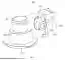


Sources:
- United States Patent and Trademark Office - verify current appl. status at the USPTO↗
Similar patent applications:
- » 20080078182
Premixing device, gas turbines comprising the premixing device, and methods of use - » 20110151389
AIR-GAS PREMIXING DEVICE IN A LOW-NOX GAS BURNER - » 20260185709
PREMIXER AND GAS DEVICE - » 20260078898
PREMIXER AND GAS DEVICE - » 20260185702
PREMIXER AND GAS DEVICE - » 20260185703
PREMIXER AND GAS DEVICE - » 20260185707
PREMIXER AND GAS DEVICE - » 20230272907
ANTI-BACKFLOW PREMIXING DEVICE AND FUEL GAS WATER HEATER - » 20160161114
Air-gas mixer device for premix burner equipment - » 20130284115
PREMIX COMBUSTION DEVICE OF GAS BURNER
Recent applications in this class:
- » 20260036299 2026-02-05
COMBUSTION SYSTEM COMPRISING AN ANNULAR SHROUD BURNER - » 20220325888 2022-10-13
COMBUSTION SYSTEM COMPRISING AN ANNULAR SHROUD BURNER - » 20210190315 2021-06-24
Combustion system comprising an annular shroud burner - » 20200240636 2020-07-30
SYSTEMS AND METHODS FOR FIRING AN INSULATOR - » 20160377285 2016-12-29
Control method using vibration control - » 20160305658 2016-10-20
Combustion controlling device and combustion system - » 20160201904 2016-07-14
Burner assembly and method for combustion of gaseous or liquid fuel - » 20160047546 2016-02-18
Burner assembly and method of combustion - » 20150101341 2015-04-16
Method for a part load CO reduction operation for a sequential gas turbine - » 20150033749 2015-02-05
System and method for barrier in passage of combustor of gas turbine engine with exhaust gas recirculation
Recent applications for this Assignee:
- » 20260185709 2026-07-02
PREMIXER AND GAS DEVICE - » 20260185707 2026-07-02
PREMIXER AND GAS DEVICE - » 20260185703 2026-07-02
PREMIXER AND GAS DEVICE - » 20260185702 2026-07-02
PREMIXER AND GAS DEVICE - » 20260118065 2026-04-30
HEAT EXCHANGER AND GAS WATER HEATER - » 20260092651 2026-04-02
VALVE DEVICE AND GAS WATER HEATER - » 20260043583 2026-02-12
WATER TANK ASSEMBLY AND GAS WATER HEATER - » 20260036298 2026-02-05
BURNER HEAD, FIRE GRATE AND GAS DEVICE - » 20260002702 2026-01-01
MAGNESIUM ROD ASSEMBLY AND WATER HEATER - » 20260002700 2026-01-01
TANK MOUNTING STRUCTURE FOR WATER HEATER AND WATER HEATER