Method and device for through-hole plating of substrates and printed circuit boards
US20050125997A1
2005-06-16
10/495,564
2002-11-14
✅ Patent granted
US 7,207,107 B2
2007-04-24
WO; PCT/EP02/12774; 20021114
WO; WO03/043394; 20030522
Minh Trinh | Donghai D. Nguyen
2022-12-01
Abstract:
A method and apparatus for through-contacting flexible substrates 1, in particular circuit boards, having electrically conductive contact zones 4, 41 present on two opposing surfaces 1a, 1b of the substrate provides that a cut 11 is produced obliquely to the surfaces of the substrate in the area of the contact zones, and the two substrate areas 20, 30 adjoining the oblique cut are moved past each other until they lock behind each other. Moving them past each other is effected by a ram 12, by the action of compressed air 13, by applying a vacuum 14 or by a driving hook 15 fixed to the cutting tool. The two steps of producing the cut and moving the two substrate areas adjoining the cut past each other are effected in a common processing station, preferably in a single operation.
Inventors:
- Ando Welling 9 🇩🇪 Isen, Germany
- Juergen Usner 1 🇩🇪 Muenchen, Germany
- Juergen Usner 1 🇩🇪 Munich, Germany
Assignee:
- GIESECKE & DEVRIENT GmbH 60 🇩🇪 Muenchen, Germany
- Giesecke & Devrient GmbH 505 🇩🇪 Munich, Germany
Interested in similar patents?
Get notified when new applications in this technology area are published.
Classification:
G06K19/0775 » CPC main
Record carriers for use with machines and with at least a part designed to carry digital markings characterised by the kind of the digital marking, e.g. shape, nature, code; Record carriers with conductive marks, printed circuits or semiconductor circuit elements, e.g. credit or identity cards also with resonating or responding marks without active components with integrated circuit chips; Constructional details, e.g. mounting of circuits in the carrier the record carrier being capable of non-contact communication, e.g. constructional details of the antenna of a non-contact smart card arrangements for connecting the integrated circuit to the antenna
B26D7/27 » CPC further
Details of apparatus for cutting, cutting-out, stamping-out, punching, perforating, or severing by means other than cutting Means for performing other operations combined with cutting
B26F1/18 » CPC further
Perforating; Punching; Cutting-out; Stamping-out; Apparatus therefor Perforating by slitting, i.e. forming cuts closed at their ends without removal of material
B26F1/22 » CPC further
Perforating; Punching; Cutting-out; Stamping-out; Apparatus therefor; Perforating by slitting, i.e. forming cuts closed at their ends without removal of material to form non-rectilinear cuts, e.g. for tabs
G06K19/077 » CPC further
Record carriers for use with machines and with at least a part designed to carry digital markings characterised by the kind of the digital marking, e.g. shape, nature, code; Record carriers with conductive marks, printed circuits or semiconductor circuit elements, e.g. credit or identity cards also with resonating or responding marks without active components with integrated circuit chips Constructional details, e.g. mounting of circuits in the carrier
H05K3/4084 » CPC further
Apparatus or processes for manufacturing printed circuits; Forming printed elements for providing electric connections to or between printed circuits; Through-connections; Vertical interconnect access [VIA] connections by deforming at least one of the conductive layers
H05K3/4084 » CPC further
Apparatus or processes for manufacturing printed circuits; Forming printed elements for providing electric connections to or between printed circuits; Through-connections; Vertical interconnect access [VIA] connections by deforming at least one of the conductive layers
H05K2201/09081 » CPC further
Indexing scheme relating to printed circuits covered by; Shape and layout; Substrate related Tongue or tail integrated in planar structure, e.g. obtained by cutting from the planar structure
H05K2201/09081 » CPC further
Indexing scheme relating to printed circuits covered by; Shape and layout; Substrate related Tongue or tail integrated in planar structure, e.g. obtained by cutting from the planar structure
H05K2201/09836 » CPC further
Indexing scheme relating to printed circuits covered by; Shape and layout; Shape or layout details not covered by a single group of - Oblique hole, via or bump
H05K2201/09836 » CPC further
Indexing scheme relating to printed circuits covered by; Shape and layout; Shape or layout details not covered by a single group of - Oblique hole, via or bump
H05K2203/0195 » CPC further
Indexing scheme relating to apparatus or processes for manufacturing printed circuits covered by; Tools for processing; Objects used during processing Tool for a process not provided for in , e.g. tool for handling objects using suction, for deforming objects, for applying local pressure
H05K2203/081 » CPC further
Indexing scheme relating to apparatus or processes for manufacturing printed circuits covered by; Treatments involving gases Blowing of gas, e.g. for cooling or for providing heat during solder reflowing
H05K2203/081 » CPC further
Indexing scheme relating to apparatus or processes for manufacturing printed circuits covered by; Treatments involving gases Blowing of gas, e.g. for cooling or for providing heat during solder reflowing
H05K2203/082 » CPC further
Indexing scheme relating to apparatus or processes for manufacturing printed circuits covered by; Treatments involving gases Suction, e.g. for holding solder balls or components
H05K2203/082 » CPC further
Indexing scheme relating to apparatus or processes for manufacturing printed circuits covered by; Treatments involving gases Suction, e.g. for holding solder balls or components
Y10T29/49117 » CPC further
Metal working; Method of mechanical manufacture; Electrical device making Conductor or circuit manufacturing
Y10T29/49124 » CPC further
Metal working; Method of mechanical manufacture; Electrical device making; Conductor or circuit manufacturing On flat or curved insulated base, e.g., printed circuit, etc.
Y10T29/49126 » CPC further
Metal working; Method of mechanical manufacture; Electrical device making; Conductor or circuit manufacturing; On flat or curved insulated base, e.g., printed circuit, etc. Assembling bases
Y10T29/49135 » CPC further
Metal working; Method of mechanical manufacture; Electrical device making; Conductor or circuit manufacturing; On flat or curved insulated base, e.g., printed circuit, etc.; Assembling to base an electrical component, e.g., capacitor, etc. with component orienting and shaping, e.g., cutting or bending, etc.
Y10T29/49156 » CPC further
Metal working; Method of mechanical manufacture; Electrical device making; Conductor or circuit manufacturing; On flat or curved insulated base, e.g., printed circuit, etc.; Manufacturing circuit on or in base with selective destruction of conductive paths
Y10T29/5136 » CPC further
Metal working; Plural diverse manufacturing apparatus including means for metal shaping or assembling Separate tool stations for selective or successive operation on work
Y10T29/5148 » CPC further
Metal working; Plural diverse manufacturing apparatus including means for metal shaping or assembling including composite tool including severing means
Y10T29/5313 » CPC further
Metal working; Means to assemble or disassemble Means to assemble electrical device
Y10T83/0207 » CPC further
Cutting; Other than completely through work thickness or through work presented
H05K3/02 IPC
Apparatus or processes for manufacturing printed circuits in which the conductive material is applied to the surface of the insulating support and is thereafter removed from such areas of the surface which are not intended for current conducting or shielding
H05K3/02 IPC
Apparatus or processes for manufacturing printed circuits in which the conductive material is applied to the surface of the insulating support and is thereafter removed from such areas of the surface which are not intended for current conducting or shielding
Description
CROSS-REFERENCE TO RELATED APPLICATIONSThis application is a National Stage of International Application No. PCT/EP02/12774, filed Nov. 14, 2002.
FIELD OF THE INVENTIONThis invention relates to a method and apparatus for through-contacting flexible substrates, in particular circuit boards, having electrically conductive contact zones disposed on two opposing surfaces of the substrate, whereby a cut is produced by means of a cutting tool through the substrate obliquely to the surfaces of the substrate in the area of the contact zones, and the two substrate areas adjoining the oblique cut are moved past each other until they lock behind each other. This achieves the result that they touch the contact zones disposed on the opposite surfaces of the substrate, that is, the contact zone on the upper side of the substrate touches the contact zone on the underside of the substrate.
DESCRIPTION OF THE BACKGROUND ARTSuch a method is described in the unpublished patent application DE 101 22 414.1. Compared to conventional through-contacting methods by which through-contacting is effected by punching or drilling a through hole and inserting a conductive contact sleeve or pouring in a conductive paste (EP-A-0 884 973), this method is fundamentally simpler. The surfaces of the substrate can be leveled again by subsequent lamination, which at the same time stabilizes the electrical connection between the two contact zones. No additional conductive material is required for producing the contact since the contact zones press firmly against each other due to the internal stress of the flexible substrate.
Such a substrate or such circuit boards are normally integrated as a card inlay into IC cards or chip cards (identity cards, credit cards, cash cards, etc.) and frequently form a separate layer of the card body. On one side of the circuit board there can be for example an integrated circuit formed by the conductive layer and having further electronic devices, while the conductive layer on the opposite side of the circuit board is formed for example as an antenna coil for noncontacting data interchange and energy transfer with external devices, which is electrically connected with the integrated circuit through the circuit board. This electrical connection through the circuit board is generally designated “through-contacting.”
Instead of IC cards, the substrate can also be used in the context of the present invention for tags, stickers and similar security elements with antenna coil technology and/or electronic inlays.
It proves to be problematic in this method that the two working steps to be performed in succession, namely the oblique cut and the urging through of the two substrate areas adjoining the cut (hereinafter also designated “contact tabs” or “through-contacting tabs”), are imprecise and lead to high reject rates. Internal tests with the method therefore required a high expenditure of manual work.
SUMMARY OF THE INVENTIONIt is the problem of the present invention to specify a concrete and reliable, simplified method for through-contacting circuit boards and the like as well as an apparatus for carrying out the method.
Therefore, the through-contacting tabs produced by the oblique cut are not pushed past each other manually; this is done mechanically by means of a separate ram or by means of compressed air or by applying a vacuum or automatically during production of the oblique cut by a driving hook fixed to the cutting tool. Single or several of these measures can also be combined with each other. The use of said mechanical aids permits the method to be automated and the reject rate to be reduced.
A special advantage is to be seen in the fact that the mechanical aids for urging through the through-contacting tabs can be combined with the cutting tool for producing the oblique cut in a common processing station. This makes it in particular possible to perform both processing steps with the substrate position unchanged, so that the mechanical aids for urging through the through-contacting tabs always act on the substrate at an exactly predetermined position relative to the previously provided cut.
It is particularly advantageous if the two steps required for through-contacting are effected in a common operation. This goal can be attained for example by the cutting tool with a driving hook fixed thereto by the cutting tool first being pushed through the substrate obliquely to the substrate plane, and one of the two thereby produced through-contacting tabs being urged behind the other through-contacting tab for example by a driving hook fixed to the cutting tool upon further advancing of the cutting tool.
The two steps of producing the cut and urging through the tab can also be integrated into one operation when applying compressed air and/or a vacuum.
Even the use of a separate ram for urging one contacting tab through behind the other contacting tab can be integrated into the working step of producing the oblique cut. In this case the contacting tabs are urged past each other by the ram before the cutting tool is withdrawn from the oblique cut. The cutting tool is preferably realized as a knife blade which is resilient perpendicular to the knife blade plane.
In accordance with a special embodiment of the invention, the cutting edge of the cutting tool is serrated and has at least one tooth. This prevents the knife from slipping after being placed on the flexible substrate and accordingly improves the precision of through-contacting.
BRIEF DESCRIPTION OF THE DRAWINGSThe invention will hereinafter be described by way of example with reference to the accompanying drawings, in which:
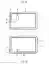
FIGS. 1a and 1b show the front and back of a flexible substrate,
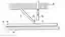
FIG. 2 shows two embodiments of an inventive apparatus for through-contacting the substrate in a side view,
FIGS. 3a and 3b show a substrate through-contacted by means of the apparatus according to FIG. 2 in cross section and in a plan view,
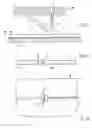
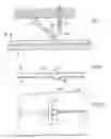
FIG. 4 shows an embodiment of the inventive apparatus according to FIG. 2,
FIGS. 5a and 5b show a substrate through-contacted by means of the apparatus according to FIG. 4 in cross section and in a plan view,
FIG. 6 shows two further embodiments of an inventive apparatus for through-contacting the substrate in a side view, and
FIG. 7 shows a cutting tool with a serrated cutting edge.
DETAILED DESCRIPTION OF THE INVENTIONFIG. 1a shows the front of a substrate 1 suitable for incorporation into a card body. On this side of the substrate a conductive layer 2 is shown in the form of a coil for noncontacting data and energy exchange with an external device. The coil 2 disposed on this side of the substrate 1 has the contact zones 4 and 5, the contact zone 5 being provided for contacting with an IC module. A further contacting of the coil with the IC module is effected via the contact zone 6 which is connected by a through-contacting at the site 8 with a second electrically conductive layer 3 in the form of a second coil on the back of the substrate 1 (FIG. 1b). A further through-contacting of the same type connects the contact zone 4 with the coil 3 at the site 7. The associated contact zones of the coil 3 on the back of the substrate are marked as 61 and 41 in FIG. 1b.
FIG. 2 jointly shows two embodiments of an inventive apparatus for carrying out the through-contacting. The two embodiments have in common that in a processing station the substrate 1 lies on a soft base 10, for example a rubber mat, and, with the position of the substrate unchanged, both a cut 11 is produced obliquely to the surfaces 1a, 1b of the substrate 1 and the through-contacting tabs 20, 30 formed by the cut are urged past each other until the tab 30 locks behind the other tab 20, as shown in FIG. 3a.
The cut 11 in the substrate 1 is preferably produced at a 45° angle relative to the substrate surfaces 1a, 1b.
The step of moving the two through-contacting tabs 20, 30 past each other is effected by means of a driving hook 15 on the knife 9 in accordance with the first embodiment shown in FIG. 2. To this end, the knife 9 mounted displaceably in the knife holder 20 is first pushed forward in the axial direction to produce the cut 11. Further advancing the knife 9 causes the driving hook 15 to come in contact with the contact tab 30 located on the right of the cut 11 in FIG. 2 and urge it back behind the contact tab 20 located on the left of the cut 11 in FIG. 2 so that the two contact tabs lock behind each other (FIG. 3a).
In accordance with the second embodiment shown in FIG. 2, a ram 12 which is movable up and down in the direction of the arrow is used instead of the driving hook 15 for moving the two through-contacting tabs 20, 30 past each other. In this case, the cut 11 is first produced by the knife 9 by the knife 9 being advanced in its axial direction and then, before or after the knife 9 has been moved back to its initial position, the ram 12 is used to again urge the contact tab 30 located on the right of the cut 11 behind the contact tab 20 located on the left of the cut 11. The ram 12 has in this case a comparatively small cross section and urges with this cross section only the central area of the right contact tab 30 under the left contact tab 20.
In a plan view, both embodiments result in a through-contacted configuration as shown in FIG. 3b. Therefore, the contact tabs 20, 30 overlap with their surfaces 1a, 1b (FIG. 3a) only in a central area of the cut 11. The thereby produced contact area between the contact zones 4 of the coil 2 and the contact zone 41 of the coil 3 is shown hatched in FIG. 3b.
After through-contacting is completed in the processing station, the substrate 1 can be removed from the processing station and for example be completed to form a plastic card in a laminating process with further plastic layers and optionally further electronic devices.
Instead of the ram with a comparatively small cross section as shown in FIG. 2, a ram extending along the total length of the cut 11 can also be used. The driving hook 15, which is preferably comparatively small and placed in the center of the knife 9 in the embodiment according to FIG. 2, can also optionally extend over the total width of the knife 9. In this case, urging the right contact tab 30 through behind the left contact tab 20 leads to tearing of at least the urged through contact tab 30 at the two cut ends. To avoid this, the alternative embodiments to the apparatus from FIG. 2 as shown in FIG. 4 provide that the knife 9 has lateral cutting elements 9a, or the ram 12 has lateral cutting elements 12a, which ensure that a clean cut 11a is produced perpendicular to the transverse extension of the cut 11 either upon production of the cut 11 by the cutting elements 9a or upon urging of the contact tabs past each other by the cutting elements 12a. The through-contacting tab 30 then has a typical tab form in the stricter sense, as indicated in FIG. 5a on the right contacting tab 30 urged downward out of the substrate plane. Said contact tab 30 is separated on three sides from the substrate 1 by the cuts 11 and 11a and connected with the substrate 1 on only one side. FIG. 5b again shows a plan view of the area of the through-contacting produced by the apparatus from FIG. 4. The concretely contacted surface between the contact zones 4 and 41 is again hatched.
FIG. 6 again shows jointly in one picture two further embodiments of an inventive apparatus for carrying out the method. In this case, the right contact tab 30 is moved past the left contact tab 20 by compressed air 13 directed to the front 1a of the contact tab 30, and/or by a vacuum applied to the back 1b of the contact tab by a vacuum pump 14. In this case, the base 10 can be a firm base, since the cut 11 is guided into the suction port of the vacuum pump 14, and the through-contacting tab 30 located on the right of the cut 11 is also moved into said suction port when moving past the contacting tab 20 located on the left of the cut 11.
FIG. 7 shows a special embodiment of the knife 9 having a serrated cutting edge. In the embodiment specifically shown, the cutting edge of the knife 9 has a single tooth 9b which serves to prevent the knife 9 from slipping after being placed on the surface 1a of the substrate 1.
Claims
1. A method for through-contacting flexible substrates (1) having electrically conductive contact zones (4, 41; 6, 61) disposed on two opposing surfaces (1a, 1b) of the substrate (1), whereby a cut (11) is produced by means of a cutting tool (9) through the substrate obliquely to the surfaces (1a, 1b) of the substrate (1) in the area of the contact zones (4, 41), characterized in that the two substrate areas (20, 30) adjoining the oblique cut (11) are moved past each other until they lock behind each other, the step of moving them past each other being performed in one operation with the production of the cut.
2. A method according to claim 1, characterized in that the adjoining substrate areas (20, 30) are moved past each other by means of at least one of a separate ram (12) or a driving device (15) disposed on the cutting tool.
3. A method according to claim 1, characterized in that the adjoining substrate areas (20, 30) are moved past each other by compressed air (13) or production of a vacuum (14).
4. A method according to claim 1, characterized in that the two steps of producing the cut and moving the two substrate areas past each other are performed with the substrate position unchanged.
5. A method according to claim 1, characterized in that the oblique cut (11) is produced at an angle of 45° to the substrate surfaces (1a, 1b).
6. An apparatus for carrying out the method according to claim 1, comprising a cutting tool (9) for producing a cut (11) through a substrate (1) obliquely to two opposing surfaces (1a, 1b) of the substrate, and a device (12; 13; 14; 15) for moving two substrate areas (20, 30) adjoining the cut (11) past each other and locking them behind each other, characterized in that the cutting tool (9) and the locking device (12; 13; 14; 15) are disposed in a common work station.
7. An apparatus according to claim 6, characterized in that the locking device comprises a ram (12).
8. An apparatus according to claim 6, characterized in that the locking device uses compressed air (13) for moving the two substrate areas adjoining the cut past each other.
9. An apparatus according to claim 6, characterized in that the locking device uses a vacuum (14) for moving the two substrate areas adjoining the cut past each other.
10. An apparatus according to claim 6, characterized in that the locking device comprises a driving hook (15) fixed to the cutting tool (9).
11. An apparatus according to claim 6, characterized in that the cutting tool (9) has a cutting edge with at least a tooth (9b).
12. An apparatus according to claim 6, characterized in that the cutting tool (9) comprises a knife blade which is resilient perpendicular to the knife blade plane.
Images & Drawings included:
Sources:
- United States Patent and Trademark Office - verify current appl. status at the USPTO↗
Recent applications in this class:
- » 20250265439 2025-08-21
Radio Frequency Identification (RFID) Tags for Metallic and Three-Dimensional (3D) Objects and Methods of Making and Using Thereof - » 20250265438 2025-08-21
Radio Frequency Identification (RFID) Tags for Metallic and Three-Dimensional (3D) Objects and Methods of Making and Using Thereof - » 20240419933 2024-12-19
LEADFRAMELESS CONTACTLESS MODULE - » 20240104331 2024-03-28
RADIOFREQUENCY TRANSCEIVER DEVICE AND METHOD FOR MANUFACTURING SAME - » 20240078406 2024-03-07
CHIP ASSEMBLY, METHOD FOR FORMING A CHIP ASSEMBLY, AND METHOD FOR USING A CHIP ARRANGEMENT - » 20240005122 2024-01-04
RADIO FREQUENCY IDENTIFICATION TAG WITH ANTENNA AND PASSIVE REFLECTOR - » 20230111259 2023-04-13
Card-type media - » 20220374673 2022-11-24
Antenna device and wireless power transmission device having the same - » 20220222501 2022-07-14
Radio Frequency Identification (RFID) Tags for Metallic and Three-Dimensional (3D) Objects and Methods of Making and Using Thereof - » 20210271949 2021-09-02
Controlled energy adsorption by self-limiting heating for curing processes
Recent applications for this Assignee:
- » 20160321851 2016-11-03
Method and apparatus for handling value documents - » 20160292951 2016-10-06
Apparatus and method for checking value documents - » 20160232735 2016-08-11
Value document and method for checking the presence of the same - » 20160232730 2016-08-11
Method for checking a value document - » 20160217640 2016-07-28
Method and system for handling value documents - » 20160215456 2016-07-28
Value document and method for checking the presence of the same - » 20160110638 2016-04-21
Optically variable security element - » 20160094341 2016-03-31
Methods and system for secure communication between an RFID tag and a reader - » 20160080930 2016-03-17
Mobile device management - » 20160055358 2016-02-25
Check of a security element furnished with magnetic materials