Electrical connector and contact
US20050130464A1
2005-06-16
11/016,405
2004-12-16
✅ Patent granted
US 7,029,292 B2
2006-04-18
-
-
Ross Gushi
2024-12-16
Abstract:
Disclosed is an electrical connector having an insulative housing and conductive connector wherein conductive connector has a distal end which is angled and generally rectangular in shape with the four corners of the rectangular shape of the distal end bent to receive a fusible material. The fusible material will generally be a solder ball. Also disclosed is a product made by the process of bending the rectangular shape of the distal end of the contact so as to receive a solder ball.
Assignee:
- Hon Hai Precision Ind. Co., Ltd. 1,929 🇹🇼 Taipei Hsien, Taiwan
Interested in similar patents?
Get notified when new applications in this technology area are published.
Classification:
H01R12/00 IPC
Structural associations of a plurality of mutually-insulated electrical connecting elements, specially adapted for printed circuits, e.g. printed circuit boards [PCBs], flat or ribbon cables, or like generally planar structures, e.g. terminal strips, terminal blocks; Coupling devices specially adapted for printed circuits, flat or ribbon cables, or like generally planar structures; Terminals specially adapted for contact with, or insertion into, printed circuits, flat or ribbon cables, or like generally planar structures
H01R12/57 » CPC main
Structural associations of a plurality of mutually-insulated electrical connecting elements, specially adapted for printed circuits, e.g. printed circuit boards [PCBs], flat or ribbon cables, or like generally planar structures, e.g. terminal strips, terminal blocks; Coupling devices specially adapted for printed circuits, flat or ribbon cables, or like generally planar structures; Terminals specially adapted for contact with, or insertion into, printed circuits, flat or ribbon cables, or like generally planar structures; Fixed connections for rigid printed circuits or like structures characterised by the terminals surface mounting terminals
H05K3/3426 » CPC further
Apparatus or processes for manufacturing printed circuits; Assembling printed circuits with electric components, e.g. with resistor electrically connecting electric components or wires to printed circuits by soldering; Surface mounted components; Leaded components characterised by the leads
H01R43/0256 » CPC further
Apparatus or processes specially adapted for manufacturing, assembling, maintaining, or repairing of line connectors or current collectors or for joining electric conductors for soldered or welded connections for soldering or welding connectors to a printed circuit board
H05K2201/10984 » CPC further
Indexing scheme relating to printed circuits covered by; Details of components or other objects attached to or integrated in a printed circuit board; Details of electrical connections of non-printed components, e.g. special leads; Other details of electrical connections Component carrying a connection agent, e.g. solder, adhesive
H05K2203/041 » CPC further
Indexing scheme relating to apparatus or processes for manufacturing printed circuits covered by; Soldering or other types of metallurgic bonding Solder preforms in the shape of solder balls
H05K2203/041 » CPC further
Indexing scheme relating to apparatus or processes for manufacturing printed circuits covered by; Soldering or other types of metallurgic bonding Solder preforms in the shape of solder balls
Y02P70/50 » CPC further
Climate change mitigation technologies in the production process for final industrial or consumer products Manufacturing or production processes characterised by the final manufactured product
Y02P70/50 » CPC further
Climate change mitigation technologies in the production process for final industrial or consumer products Manufacturing or production processes characterised by the final manufactured product
Description
1. CROSS-REFERENCE TO RELATED APPLICATIONSThis application is a continuation of Provisional Application No. 60/530,350 filed Dec. 16, 2003.
2. BACKGROUND OF THE INVENTIONThe field of endeavor of this electrical connector and contact is, generally, Class 439, Sub-class 83, relating to contacts to be soldered to a printed circuit board. The invention relates to the positioning of a solder ball on the contact platform or pad.
The materials set forth in connection with this U.S. patent application describe an electrical connector and associated contact—see, e.g., U.S. Pat. Nos. 5,997,317, 6,095,842, 6,099,321, 6,113,411, 6,113,412, 6,116,922, 6,116,923, 6,132,222, 6,142,810, 6,142,811, 6,171,156, 6,213,807 and 6,267,615, which are all hereby incorporated by reference. Further description of this invention is set forth below and in the attached drawings (FIGS. 1-3).
3. BRIEF SUMMARY OF THE INVENTIONThis invention relates to a new, economical connector platform or pad which provides for positioning a solder ball on a contact without using a deformation in the housing of the connector for positioning the solder ball and without using a “dimple” on the platform or pad of the contact for positioning the solder ball.
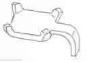
4. BRIEF DESCRIPTION OF THE DRAWINGSFIG. 1 depicts the platform or pad of a generally rectangular connector in which the four corners of the platform are bent at an angle to receive a ball of solder.
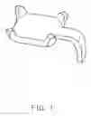
FIG. 2 depicts FIG. 1 with a solder ball attached to the platform from the top.
FIG. 3 depicts a view generally from the side and top of the platform with a solder ball attached thereto from the bottom.
DETAILED DESCRIPTION OF THE INVENTIONThe present invention pertains primarily to Ball Grid Array (“BGA”) connectors, although it has other electrical/connector related applications. Ball Grid Array is presently becoming the dominant means of connecting sockets and all kinds of connectors to the Printed Circuit Boards. One of the important manufacturing steps is the attachment of the solder ball to the contact. The standard procedure is to either apply solder past, or flux, to the surface of the pad or platform to which the ball is to be attached.
If the ball is made of 60-40 alloy, it is melted onto the pad directly. Some contacts are made of some copper alloy, over-plated with Nickel. Nickel is usually covered by a film, which is some form of “oxide.” The composition of this film varies according to the environment to which Nickel was exposed, when first plated. When such film is present, it is “PASSIVE”, i.e., it is not solderable using flux of the type which is acceptable for soldering components to the circuit boards (PCB). However, an extra “active” flux renders passive Nickel solderable. Be that as it may, the solder ball needs to be positioned (oriented) on the center of the Pad, or Platform on the contact. Other BGA connectors use the geometry of the housing hole to receive the solder paste and place it in contact with the bottom of the contact terminal. At the melting temperature, the paste, which contains flux, melts. Molten solder assumes a shape by surface tension, thus the shape is a partially distorted sphere, the distortion of the sphere is the result of wetting of the contact end.
In the prior art, the “positioning” of the ball is made by means of the housing (other BGA connectors), or by making a small Dimple in the center of the pad. This invention provides a new, economical means of the ball positioning.
Proposed herewith is a simple, economical structure and method of implementation, without increasing the material cost or the manufacturing cost. The method consists of bending the four corners of the Pad or Platform, whatever the choice of jargon words better applies. Such corners or “fingers”, shaped so that their inner surface is made tangent to the ball, forming a nest, shall position the ball even more securely than the “dimple.” The changes in the stamping tool can be implemented at a small cost. The new structure of the pad is illustrated in FIGS. 1, 2, and 3 depicting the pad and the pad with the ball in place. Most people are using a high melting point alloy for the ball, requiring the use of solder paste. Some people are using 60-40 alloy, which is the same as the usual paste alloy. With the proper flux the passive surface of nickel is made wettable with solder, thus, depending on the placement of flux either only the center of the pad, or the entire pad, including the bent-up corners shall be covered by solder. The finished geometry shall be a rectangular base with a spherical projection on top.
The implementing of this design has many additional advantages which should not be limited to any single embodiment, but rather construed in breadth and scope in accordance with the claims.
Claims
1. An electrical connector having a conductive contact comprising:
an insulative housing adapted to engage the conductive contact,
the conductive contact having a distal end wherein the distal end is angled and has a generally rectangular shape such that the four corners of the rectangular shape of the distal end are bent to adapt the distal end to receive a mass of fusible material.
2. The electrical connector of claim 1 wherein the conductive contact is made of a copper alloy.
3. The electrical connector of claim 2 wherein the conductive contact is over-plated with nickel.
4. The electrical connector of claim 1 wherein the mass of the fusible material is generally ellipsoidal.
5. The electrical connector of claim 1 wherein the mass of the fusible material is generally spherical.
6. A product of a method for placing a fusible material on an electrical connector having a conductive contact comprising:
providing an insulative housing adapted to engage the conductive contact,
providing the conductive contact having a distal end wherein the distal end is angled and has a generally rectangular shape,
bending the four corners of the rectangular shape of the distal end to adapt the distal end to receive a mass of fusible material.
7. The product of claim 6 wherein the conductive contact is made of a copper alloy.
8. The product of claim 7 wherein the conductive contact is over-plated with nickel.
9. The product of claim 6 wherein the mass of the fusible material is generally ellipsoidal.
10. The product of claim 6 wherein the mass of the fusible material is generally spherical.
Images & Drawings included:


Sources:
- United States Patent and Trademark Office - verify current appl. status at the USPTO↗
Similar patent applications:
- » 20190210879
ELECTRICAL CONTACT, CONNECTOR, AND METHOD FOR PRODUCING ELECTRICAL CONTACT - » 20140107754
Terminal ring configuration to prevent improper IS4 lead connector electrical contact with DF4 connector port - » 20230268684
ELECTRICAL CONNECTOR, CONTACT INSERT AND METHOD FOR PRODUCING AN ELECTRICAL CONNECTOR - » 20070026723
Electrical connector contact - » 20060035524
Electrical connector contact - » 20070015397
Electrical connector contact - » 20050020136
Electrical connector contact - » 11580979
Compressed contact electrical connector - » 18781483
Multiple-contact electrical connector assembly - » 10839258
Electrical connector contact configurations
Recent applications in this class:
- » 20250183568 2025-06-05
ELECTRONIC DEVICE - » 20240243496 2024-07-18
METHOD AND APPARATUS FOR SURFACE MOUNT CONNECTIONS - » 20240222888 2024-07-04
CONNECTOR, CONNECTOR PREPARATION METHOD, INTERCONNECTION SYSTEM, AND COMMUNICATION DEVICE - » 20240186730 2024-06-06
Electrical Connector, Connecting Body Between a Circuit Board and Electrical Connector - » 20240170868 2024-05-23
Electrical Connector with Meander and Opening - » 20240162637 2024-05-16
Electronic Device - » 20240145952 2024-05-02
GOLD FINGER CONNECTOR AND MEMORY STORAGE DEVICE - » 20240106140 2024-03-28
HIGH SPEED ELECTRICAL CONNECTOR AND PRINTED CIRCUIT BOARD THEREOF - » 20240106139 2024-03-28
CONNECTOR TO ELECTRICALLY COUPLE MULTIPLE SUBSTRATES - » 20240039188 2024-02-01
RECEPTACLE MODULE FOR A COMMUNICATION SYSTEM
Recent applications for this Assignee:
- » 20110045702 2011-02-24
Electrical cable connector assembly with improved wire organizer - » 20110021088 2011-01-27
Electrical connector with improved contact footprints - » 20110021082 2011-01-27
High density backplane connector having improved terminal arrangement - » 20110008982 2011-01-13
N-in-1 card connector - » 20110005825 2011-01-13
Cable assembly with EMI protection - » 20110003508 2011-01-06
Electrical connector rotatably mounted to a portable device - » 20100330822 2010-12-30
Electrical connector having contact with upper terminal and lower terminal - » 20100317218 2010-12-16
Electrical connector assembly with latching mechanism - » 20100297861 2010-11-25
Socket connector having improved actuating mechanism for driving moving plate - » 20100291799 2010-11-18
Shielded connector with enlarged base supporting cantilevered brackets extending from the shielded connector