Bonding arm swinging type bonding apparatus
US20050184127A1
2005-08-25
11/061,272
2005-02-17
✅ Patent granted
US 7,389,805 B2
2008-06-24
-
-
Philip Tucker | Sing P. Chan
2025-02-17
Abstract:
A bonding arm swinging type bonding apparatus that has a rotational center 13 of the bonding arm 1 beneath the bonding arm. The rotating shaft parts 11 of circular arc form rotary motors 10 that rotate about the rotational center 13 of the bonding arm 1 are attached to the bonding arm 1, and the rotating shaft parts 21 of circular arc form air bearings 20 that rotate about this rotational center 13 are provided so that the rotating shaft parts of the circular arc form air bearings 20 are rotatable as a unit with the rotating shaft parts 11 of the rotary motors 10.
Inventors:
- Osamu Kakutani 8 🇯🇵 Oume-shi, Japan
- Yutaka Kondo 9 🇯🇵 Tachikawa-shi, Japan
- Yoshihiko Seino 1 🇯🇵 Musashimurayama-shi, Japan
- Osamu Kakutani 8 🇯🇵 Oume, Japan
- Yutaka Kondo 8 🇯🇵 Tachikawa, Japan
- Yoshihiko Seino 2 🇯🇵 Musashimurayama, Japan
Assignee:
- Kabushiki Kaisha Shinkawa 67 🇯🇵 Tokyo, Japan
Interested in similar patents?
Get notified when new applications in this technology area are published.
Classification:
B23K37/02 IPC
Auxiliary devices or processes, not specially adapted to a procedure covered by only one of the preceding main groups Carriages for supporting the welding or cutting element
B23K20/005 » CPC main
Non-electric welding by applying impact or other pressure, with or without the application of heat, e.g. cladding or plating specially adapted for particular articles or work; Wire welding Capillary welding
H01L24/78 » CPC further
Arrangements for connecting or disconnecting semiconductor or solid-state bodies; Methods or apparatus related thereto; Apparatus for manufacturing arrangements for connecting or disconnecting semiconductor or solid-state bodies Apparatus for connecting with wire connectors
H01L2224/7835 » CPC further
Indexing scheme for arrangements for connecting or disconnecting semiconductor or solid-state bodies and methods related thereto as covered by; Apparatus for manufacturing arrangements for connecting or disconnecting semiconductor or solid-state bodies and for methods related thereto; Apparatus for connecting with wire connectors; Means for applying energy, e.g. heating means by means of pressure by ultrasonic vibrations Stable and mobile yokes
H01L2224/78822 » CPC further
Indexing scheme for arrangements for connecting or disconnecting semiconductor or solid-state bodies and methods related thereto as covered by; Apparatus for manufacturing arrangements for connecting or disconnecting semiconductor or solid-state bodies and for methods related thereto; Apparatus for connecting with wire connectors; Means for moving parts; Upper part of the bonding apparatus, i.e. bonding head, e.g. capillary or wedge Rotational mechanism
H01L2224/78823 » CPC further
Indexing scheme for arrangements for connecting or disconnecting semiconductor or solid-state bodies and methods related thereto as covered by; Apparatus for manufacturing arrangements for connecting or disconnecting semiconductor or solid-state bodies and for methods related thereto; Apparatus for connecting with wire connectors; Means for moving parts; Upper part of the bonding apparatus, i.e. bonding head, e.g. capillary or wedge; Rotational mechanism Pivoting mechanism
Y10S228/904 » CPC further
Metal fusion bonding Wire bonding
H01L2224/78301 » CPC further
Indexing scheme for arrangements for connecting or disconnecting semiconductor or solid-state bodies and methods related thereto as covered by; Apparatus for manufacturing arrangements for connecting or disconnecting semiconductor or solid-state bodies and for methods related thereto; Apparatus for connecting with wire connectors; Means for applying energy, e.g. heating means by means of pressure Capillary
H01L2224/48 » CPC further
Indexing scheme for arrangements for connecting or disconnecting semiconductor or solid-state bodies and methods related thereto as covered by; Means for bonding being attached to, or being formed on, the surface to be connected, e.g. chip-to-package, die-attach, "first-level" interconnects; Manufacturing methods related thereto; Wire connectors; Manufacturing methods related thereto; Structure, shape, material or disposition of the wire connectors after the connecting process of an individual wire connector
H01L2924/00014 » CPC further
Indexing scheme for arrangements or methods for connecting or disconnecting semiconductor or solid-state bodies as covered by; Technical content checked by a classifier the subject-matter covered by the group, the symbol of which is combined with the symbol of this group, being disclosed without further technical details
H01L2224/45099 » CPC further
Indexing scheme for arrangements for connecting or disconnecting semiconductor or solid-state bodies and methods related thereto as covered by; Means for bonding being attached to, or being formed on, the surface to be connected, e.g. chip-to-package, die-attach, "first-level" interconnects; Manufacturing methods related thereto; Wire connectors; Manufacturing methods related thereto; Structure, shape, material or disposition of the wire connectors prior to the connecting process of an individual wire connector; Core members of the connector Material
B32B37/00 IPC
Methods or apparatus for making layered products; Treatment of the layers or of the layered products
B32B37/00 IPC
Methods or apparatus for laminating, e.g. by curing or by ultrasonic bonding
B32B39/00 IPC
Layout of apparatus or plants, e.g. modular laminating systems
Description
BACKGROUND OF THE INVENTION1. Technical Field
The present invention relates to a bonding arm swinging type bonding apparatus in which the swinging center of the bonding arm during bonding can be set on a bonding surface.
2. Description of the Related Art
Japanese Patent Application Laid-Open (Kokai) No. 2003-347349, for instance, discloses an example of a bonding arm swinging type bonding apparatus. In this bonding arm swinging type bonding apparatus, the bonding head is provided so that it can be maintained in a position that is higher than the work plane and so that the bonding arm need not be lengthened even in cases where the bonding area is broad. Thus, in this bonding apparatus, a high-speed operation can be performed while suppressing any increase in the inertia of the bonding arm.
More specifically, the above-described prior art bonding apparatus comprises a bonding arm which has a capillary attached to a tip end thereof, a driving motor which is attached to the rear end portion of this bonding arm in order to drive the bonding arm, and a bonding head in which a circular arc form window structure is formed so that the window supports supporting portions that are disposed on both sides of the bonding arm. The center of the circular arc of the window is disposed on the plane of the bonding surface, and the supporting portions of the bonding arm move along the circular arc shape in the circular arc form window of the bonding head.
In the above-described prior art, a bonding arm that is short in length can be used. Accordingly, this bonding apparatus can reduce the inertial moment of the bonding arm. However, since the driving motor is installed on the rear end portion of the bonding arm, which is apart from the rotational center of the bonding arm, there are limitations to the reduction in the inertial moment that can be achieved.
BRIEF SUMMARY OF THE INVENTIONAccordingly, the object of the present invention is to provide a bonding arm swinging type bonding apparatus in which a remarkable reduction in inertial moment is achievable and which is able to make a high-speed operation of the boding arm.
The above object is accomplished by a unique structure of the present invention for a bonding arm swinging type bonding apparatus that has a bonding arm rotational center beneath the bonding arm; and in the present invention,
-
- a first rotating shaft part, which is the rotating shaft part of a circular arc form rotary motor and rotates about the rotational center of the bonding arm, is attached to the bonding arm; and
- a second rotating shaft part, which is the rotating shaft part of a circular arc form bearing and rotates about the rotational center of the rotary motor, is provided so that the second rotating shaft part is rotatable as a unit with the first rotating shaft part of the rotary motor.
In the above structure of the bonding arm swinging type bonding apparatus of the present invention, the bearing is an air bearing, a rolling bearing or a sliding bearing.
Since the rotational centers of the rotary motor and air bearing, rolling bearing or sliding bearing are provided at the rotational center of the bonding arm, the inertial moment of the bonding arm is extremely low and a significantly high-speed operation of the bonding arm is possible.
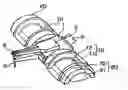
BRIEF DESCRIPTION OF THE DRAWINGSFIG. 1 is a perspective view of the essential portion of one embodiment of the bonding arm swinging type bonding apparatus of the present invention; and
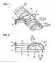
FIG. 2 is a side view thereof.
DETAILED DESCRIPTION OF THE INVENTIONOne embodiment of the present invention will be described with reference to FIGS. 1 and 2.
A capillary 2 is attached to the tip end portion of a bonding arm 1, and a wire 3 wound on a wire spool (not shown) passes through the capillary 2. A clamper arm 5, which has a wire clamper 4 that clamps the wire 3, is provided above the bonding arm 1, and this clamper arm 5 is attached to the bonding arm 1. The reference numeral 6 is a sensor scale.
Circular arc form rotary motors 10 are disposed on both ends of the bonding arm 1, and the rotating shaft parts 11 of the rotary motors 10 are attached to the side surfaces of the bonding arm 1. The rotating shaft parts 11 of the rotary motors 10 is in a shape of a circular arc that is smaller than a semicircle, and their rotational centers 13 are positioned within the bonding surface 14 during bonding. The rotating shaft parts 11 of the rotary motors 10 are held by attraction to the fixing portions 12 of the rotary motors 10 by a magnetic force of the rotary motors 10.
Circular arc form air bearings 20 are disposed on both sides of the rotary motors 10. The rotating shaft parts 21 of the air bearings 20 are integrally attached to the rotating shaft parts 11 of the rotary motors 10, and the fixing portions 22 of the air bearings 20 are integrally attached to the fixing portions 12 of the rotary motors 10. The rotational centers of the rotating shaft parts 21 of the air bearings 20 are the rotational centers 13 of the rotating shaft parts 11 of the rotary motors 10.
Though not shown in FIG. 1 or 2, the fixing portions 12 of the rotary motors 10 are fastened to the bonding head, the upper surface of the bonding head is fastened to an XY table that is driven in the directions of the X and Y axes, and the XY table is fastened to the ceiling part of the stand of the bonding apparatus.
In the above structure, when the bonding apparatus is stopped (off), the rotating shaft parts 11 of the rotary motors 10 are held by the magnets of the fixing portions 12. Thus, the bonding arm 1 (which forms an integral unit with the rotating shaft parts 11 of the rotary motors 10) and the rotating shaft parts 21 of the air bearings 20 are also held by the fixing portions 12 of the rotary motors 10.
On the other hand, when the bonding apparatus is in operation (on), and the capillary 2 is moved vertically, air that overcomes the attractive force created by the magnetic force of the rotary motors 10 is supplied to the air bearings 20, so that the rotating shaft parts 21 of the air bearings 20 and the rotating shaft parts 11 of the rotary motors 10 are put into a floating state. Accordingly, when an operating current is supplied to the rotary motors 10, the rotating shaft parts 11 of the rotary motors 10, the rotating shaft parts 21 of the air bearings 20 and the bonding arm 1 swing about the rotational center 13. As a result of the swinging of the bonding arm 1, the wire 3 passing through the capillary 2 is bonded to the workpiece.
As seen from the above, according to the present invention, in a bonding arm swinging type bonding apparatus which has a rotational center 13 of the bonding arm 1 located beneath this bonding arm 1, the rotational shaft parts (or first rotational shaft parts) 11 of the circular arc form rotary motors 10 that rotate about the rotational center 13 of the bonding arm 1 are attached to the bonding arm 1, and the rotating shaft parts (or second rotational shaft parts) 21 of the circular arc form air bearings 20 that rotate about the rotational center 13 are provided so that the (second) rotating shaft parts are rotatable as a unit with the (first) rotating shaft parts 11 of the rotary motors 10. In other word, the rotational centers of the rotary motors 10 and air bearings 20 are provided at the rotational center 13 of the bonding arm 1; accordingly, the inertial moment of the bonding arm is extremely low, and a significantly high-speed operation of the bonding arm can be accomplished.
In the above-described description, air bearings are used as the bearings. However, it goes without saying that the bearing used can be rolling bearings, sliding bearings, etc.
Claims
1. A bonding arm swinging type bonding apparatus which has a bonding arm rotational center beneath a bonding arm, wherein
a first rotating shaft part, which is a rotating shaft part of a circular arc form rotary motor and rotates about said rotational center of said bonding arm, is attached to said bonding arm, and
a second rotating shaft part, which is a rotating shaft part of a circular arc form bearing and rotates about a rotational center of said rotary motor, is provided so that said second rotating shaft part is rotatable as a unit with said first rotating shaft part.
2. The bonding arm swinging type bonding apparatus according to claim 1, wherein said bearing is one selected from the group consisting of an air bearing, a rolling bearing and a sliding bearing.
Images & Drawings included:
Sources:
- United States Patent and Trademark Office - verify current appl. status at the USPTO↗
Recent applications in this class:
- » 20220134468 2022-05-05
Capillary guide device and wire bonding apparatus - » 20210094118 2021-04-01
Wire clamping system for fully automatic wire bonding machine - » 20170209955 2017-07-27
Capillary alignment jig for wire bonder - » 20120318853 2012-12-20
HEATER BLOCK FOR WIRE BONDING SYSTEM - » 20120138662 2012-06-07
WIRE BONDING METHOD - » 20120037687 2012-02-16
Capillary and ultrasonic transducer for ultrasonic bonding - » 20120031955 2012-02-09
Wire bonding apparatus with a textured capillary surface enabling high-speed wedge bonding of wire bonds - » 20110277861 2011-11-17
Ventilating apparatus - » 20110277858 2011-11-17
Ventilating apparatus - » 20110259941 2011-10-27
APPARATUS FOR MONITORING BONDING SURFACE BOUNCING, WIRE BONDING APPARATUS HAVING THE SAME AND METHOD FOR MONITORING BONDING SURFACE BOUNCING
Recent applications for this Assignee:
- » 20120018491 2012-01-26
Ultrasonic horn - » 20120018490 2012-01-26
Ultrasonic horn - » 20120018489 2012-01-26
Ultrasonic horn - » 20110079904 2011-04-07
Semiconductor device - » 20100248470 2010-09-30
Method of manufacturing semiconductor device - » 20100207280 2010-08-19
Wire bonding method and semiconductor device - » 20100206849 2010-08-19
Wire bonding apparatus, record medium storing bonding control program, and bonding method - » 20100148369 2010-06-17
Wire bonding method and semiconductor device - » 20090308914 2009-12-17
Wire bonding method - » 20090194577 2009-08-06
Wire bonding method