Stacked module systems and method
US20060263938A1
2006-11-23
11/411,185
2006-04-25
✅ Patent granted
US 7,323,364 B2
2008-01-29
-
-
Michael Lebentritt | Andre Stevenson
2026-06-17
Abstract:
A combination composed from a form standard and a CSP is attached to flex circuitry. Solder paste is applied to first selected locations on the flex circuitry and adhesive is applied to second selected locations on the flex circuitry. The flex circuitry and the combination of the form standard and CSP are brought into proximity with each other. During solder reflow operation, a force is applied that tends to bring the combination and flex circuitry closer together. As the heat of solder reflow melts the contacts of the CSP, the combination collapses toward the flex circuitry displacing the adhesive as the solder paste and contacts merge into solder joints. In a preferred embodiment, the form standard will be devised of heat transference material, a metal, for example, such as copper would be preferred, to improve thermal performance. In other embodiments, the methods of the invention may be used to attach a CSP without a form standard to flex circuitry.
Inventors:
- James Douglas Wehrly, Jr. 50 🇺🇸 Austin, TX, United States
- Julian Partridge 31 🇺🇸 Austin, TX, United States
- James Douglas Wehrly 54 🇺🇸 Austin, TX, United States
- David Roper 7 🇺🇸 Austin, TX, United States
Assignee:
- STAKTEK GROUP L.P. 42 🇺🇸 Austin, TX, United States
Interested in similar patents?
Get notified when new applications in this technology area are published.
Classification:
H05K3/3436 » CPC main
Apparatus or processes for manufacturing printed circuits; Assembling printed circuits with electric components, e.g. with resistor electrically connecting electric components or wires to printed circuits by soldering; Surface mounted components; Leadless components having an array of bottom contacts, e.g. pad grid array or ball grid array components
H01L25/105 » CPC further
Assemblies consisting of a plurality of individual semiconductor or other solid state devices ; Multistep manufacturing processes thereof all the devices being of a type provided for in the same subgroup of groups - , e.g. assemblies of rectifier diodes the devices having separate containers the devices being of a type provided for in group
H01L25/50 » CPC further
Assemblies consisting of a plurality of individual semiconductor or other solid state devices ; Multistep manufacturing processes thereof Multistep manufacturing processes of assemblies consisting of devices, each device being of a type provided for in group or
H01L23/36 » CPC further
Details of semiconductor or other solid state devices; Arrangements for cooling, heating, ventilating or temperature compensation ; Temperature sensing arrangements Selection of materials, or shaping, to facilitate cooling or heating, e.g. heatsinks
H01L23/49816 » CPC further
Details of semiconductor or other solid state devices; Arrangements for conducting electric current to or from the solid state body in operation, e.g. leads, terminal arrangements ; Selection of materials therefor consisting of soldered constructions; Leads, on insulating substrates,; Additional leads joined to the metallisation on the insulating substrate, e.g. pins, bumps, wires, flat leads Spherical bumps on the substrate for external connection, e.g. ball grid arrays [BGA]
H01L23/4985 » CPC further
Details of semiconductor or other solid state devices; Arrangements for conducting electric current to or from the solid state body in operation, e.g. leads, terminal arrangements ; Selection of materials therefor consisting of soldered constructions; Leads, on insulating substrates, Flexible insulating substrates
H01L2224/16 » CPC further
Indexing scheme for arrangements for connecting or disconnecting semiconductor or solid-state bodies and methods related thereto as covered by; Means for bonding being attached to, or being formed on, the surface to be connected, e.g. chip-to-package, die-attach, "first-level" interconnects; Manufacturing methods related thereto; Bump connectors; Manufacturing methods related thereto; Structure, shape, material or disposition of the bump connectors after the connecting process of an individual bump connector
H01L2224/73253 » CPC further
Indexing scheme for arrangements for connecting or disconnecting semiconductor or solid-state bodies and methods related thereto as covered by; Means for bonding being of different types provided for in two or more of groups; Location after the connecting process on different surfaces Bump and layer connectors
H01L2225/1041 » CPC further
Details relating to assemblies covered by the group but not provided for in its subgroups; All the devices being of a type provided for in the same subgroup of groups - the devices having separate containers the devices being of a type provided for in group the containers being in a stacked arrangement Special adaptations for top connections of the lowermost container, e.g. redistribution layer, integral interposer
H01L2225/1058 » CPC further
Details relating to assemblies covered by the group but not provided for in its subgroups; All the devices being of a type provided for in the same subgroup of groups - the devices having separate containers the devices being of a type provided for in group the containers being in a stacked arrangement; Details of electrical connections between containers Bump or bump-like electrical connections, e.g. balls, pillars, posts
H01L2225/107 » CPC further
Details relating to assemblies covered by the group but not provided for in its subgroups; All the devices being of a type provided for in the same subgroup of groups - the devices having separate containers the devices being of a type provided for in group the containers being in a stacked arrangement; Details of electrical connections between containers Indirect electrical connections, e.g. via an interposer, a flexible substrate, using TAB
H05K1/189 » CPC further
Printed circuits; Printed circuits structurally associated with non-printed electric components characterised by the use of a flexible or folded printed circuit
H05K1/189 » CPC further
Printed circuits; Printed circuits structurally associated with non-printed electric components characterised by the use of a flexible or folded printed circuit
H05K3/305 » CPC further
Apparatus or processes for manufacturing printed circuits; Assembling printed circuits with electric components, e.g. with resistor; Surface mounted components, e.g. affixing before soldering, aligning means, spacing means Affixing by adhesive
H05K3/305 » CPC further
Apparatus or processes for manufacturing printed circuits; Assembling printed circuits with electric components, e.g. with resistor; Surface mounted components, e.g. affixing before soldering, aligning means, spacing means Affixing by adhesive
H05K2203/0278 » CPC further
Indexing scheme relating to apparatus or processes for manufacturing printed circuits covered by; Details related to mechanical or acoustic processing, e.g. drilling, punching, cutting, using ultrasound Flat pressure, e.g. for connecting terminals with anisotropic conductive adhesive
Y02P70/50 » CPC further
Climate change mitigation technologies in the production process for final industrial or consumer products Manufacturing or production processes characterised by the final manufactured product
Y02P70/50 » CPC further
Climate change mitigation technologies in the production process for final industrial or consumer products Manufacturing or production processes characterised by the final manufactured product
H01L2924/00014 » CPC further
Indexing scheme for arrangements or methods for connecting or disconnecting semiconductor or solid-state bodies as covered by; Technical content checked by a classifier the subject-matter covered by the group, the symbol of which is combined with the symbol of this group, being disclosed without further technical details
H01L2924/00011 » CPC further
Indexing scheme for arrangements or methods for connecting or disconnecting semiconductor or solid-state bodies as covered by; Technical content checked by a classifier Not relevant to the scope of the group, the symbol of which is combined with the symbol of this group
H01L2224/0401 » CPC further
Indexing scheme for arrangements for connecting or disconnecting semiconductor or solid-state bodies and methods related thereto as covered by; Means for bonding being attached to, or being formed on, the surface to be connected, e.g. chip-to-package, die-attach, "first-level" interconnects; Manufacturing methods related thereto; Bonding areas; Manufacturing methods related thereto; Structure, shape, material or disposition of the bonding areas prior to the connecting process Bonding areas specifically adapted for bump connectors, e.g. under bump metallisation [UBM]
H01L21/00 IPC
Processes or apparatus adapted for the manufacture or treatment of semiconductor or solid state devices or of parts thereof
H01L21/44 IPC
Processes or apparatus adapted for the manufacture or treatment of semiconductor or solid state devices or of parts thereof; Manufacture or treatment of semiconductor devices or of parts thereof the devices having at least one potential-jump barrier or surface barrier, e.g. PN junction, depletion layer or carrier concentration layer the devices having semiconductor bodies not provided for in groups, , , and with or without impurities, e.g. doping materials Manufacture of electrodes on semiconductor bodies using processes or apparatus not provided for in groups -
Description
RELATED APPLICATIONSThis application is a continuation of U.S. patent application Ser. No. 11/131,812 filed May 18, 2005, now U.S. Pat. No. 7,033,861 B1, which is incorporated herein for all purposes.
U.S. patent application Ser. No. 10/453,398, filed Jun. 3, 2003, is incorporated herein by reference for all purposes.
TECHNICAL FIELDThe present invention relates to aggregating integrated circuits and, in particular, to methods for creating high density modules from chip-scale type devices.
BACKGROUND OF THE INVENTIONA variety of techniques are used to stack packaged integrated circuits. Some methods require special packages, while other techniques stack conventional packages.
The predominant package configuration employed during the past decade has encapsulated an integrated circuit (IC) in a plastic surround typically having a rectangular configuration. The enveloped integrated circuit is connected to the application environment through leads emergent from the edge periphery of the plastic encapsulation. Such “leaded packages” have been the constituent elements most commonly employed by techniques for stacking packaged integrated circuits.
Leaded packages play an important role in electronics, but efforts to miniaturize electronic components and assemblies have driven development of technologies that preserve circuit board surface area. Because leaded packages have leads emergent from peripheral sides of the package, leaded packages occupy more than a minimal amount of circuit board surface area. Consequently, alternatives to leaded packages known as chip scale packaging or “CSP” have recently gained market share.
CSP refers generally to packages that provide connection to an integrated circuit through a set of contacts (often embodied as “bumps” or “balls”) arrayed across a major surface of the package. Instead of leads emergent from a peripheral side of the package, contacts are placed on a major surface and typically emerge from the planar bottom surface of the package. The absence of “leads” on package sides renders most stacking techniques devised for leaded packages inapplicable for CSP stacking.
A variety of previous techniques for stacking CSPs may present complex assembly problems. What is needed, therefore, is a technique and system for stacking CSPs that provides a thermally-efficient, reliable structure that performs well at higher frequencies but does not add excessive height to the stack yet allows efficient production at reasonable cost with readily understood and managed materials and methods.
SUMMARY OF THE INVENTIONThe present invention stacks chip scale-packaged integrated circuits (CSPs) into modules that conserve PWB or other board surface area. Although the present invention is applied most frequently to chip scale packages that contain one die, it may be employed with chip scale packages that include more than one integrated circuit die. Multiple numbers of CSPs may be stacked in accordance with the present invention. The CSPs employed in stacked modules devised in accordance with the present invention are connected with flex circuitry. That flex circuitry may exhibit one or two or more conductive layers.
A combination composed from a form standard and a CSP is attached to flex circuitry. Solder paste is applied to first selected locations on the flex circuitry and adhesive is applied to second selected locations on the flex circuitry. The flex circuitry and the combination of the form standard and CSP are brought into proximity with each other. During solder reflow operation, a force is applied that tends to bring the combination and flex circuitry closer together. As the heat of solder reflow melts the contacts of the CSP, the combination collapses toward the flex circuitry displacing the adhesive as the solder paste and contacts merge into solder joints. In a preferred embodiment, the form standard will be devised of heat transference material, a metal, for example, such as copper would be preferred, to improve thermal performance. In other embodiments, the methods of the invention may be used to attach a CSP without a form standard to flex circuitry.
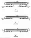
SUMMARY OF THE DRAWINGSFIG. 1 illustrates a step in a prior art method for constructing a high-density circuit module.
FIG. 2 depicts a step in a prior art method for constructing a high-density circuit module.
FIG. 3 depicts a step in a prior art method for constructing a high-density circuit module.
FIG. 4 depicts a step in a method for constructing a high-density circuit module in accordance with a preferred embodiment of the present invention.
FIG. 5 depicts a step in a method for construction of a high-density circuit module in accordance with a preferred embodiment of the present invention.
FIG. 6 depicts a step in a method for construction of a high-density circuit module in accordance with a preferred embodiment of the present invention.
FIG. 7 depicts a high-density circuit module in accordance with a preferred embodiment of the present invention.
DESCRIPTION OF PREFERRED EMBODIMENTSFIGS. 1-3 depict steps in a prior art method for constructing a high-density circuit module. FIG. 1 depicts a CSP 18 attached with adhesive 36 to form standard 34. In the configurations depicted, form standard 34 is devised to be employed with a CSP to provide a standard form for flex circuitry connector(s). Contacts 28 of CSP 18 have been compressed in a solid or semi-solid state and solder paste 41 and adhesive 43 have been applied to flex circuitry 30 and 32. FIG. 2 depicts a step in a prior art method for construction of a high-density module. Contacts 28 and solder paste sites 41 have come into contact as have form standard 34 and adhesive sites 43. FIG. 3 illustrates how solder paste sites 41 and compressed contacts 28 have merged to form solder joints and flex circuitry 30 and 32 has been wrapped about CSP 18.
FIG. 4 depicts a method in accordance with a preferred embodiment of the present invention. CSP 18 and form standard 34 are attached with adhesive 36 to form a primary combination 50. The depicted configuration of form standard 34 is one of many that can provide a standard form about which flex circuitry may be disposed. This allows a connective design implemented in flex circuitry to be used with CSPs of a variety of designs and configurations. Form standard 34 may also provide thermal advantages particularly when devised from metallic materials such as copper and copper alloys for example. Other configurations of form standard 34 may be employed with the present invention including but not limited to those that extend across the bottom surface 19 of CSP 18. Further, some form standards may not extend beyond the perimeter of CSP 18. Still other embodiments may not employ a form standard and may use the methods of the present invention to affix flex circuitry to CSP bodies.
Flex circuitry in this embodiment is comprised of flex circuits 30 and 32. Other embodiments may use one contiguous flex circuit or several and the flex circuitry may be flexible throughout or flexible in some areas and rigid in other areas. Flex circuitry has solder paste applied at selected sites as represented by reference 41 and an adhesive at selected sites identified by reference 44. The adhesive is, preferably, a thermoset adhesive or epoxy that will not soften during subsequent reflow operations such as exposure to 200-250 degrees Centigrade, for example.
In FIG. 5, the primary combination and the flex circuitry have been disposed in proximity to each other. Typically, there will be contact between contacts 28 and solder paste sites 41 but a large gap “G” between flex circuitry and form standard 34 will be exhibited because primary combination 50 is suspended above flex circuits 30 and 32 by the adhesive 44 and the uncompressed height of contacts 28 and solder paste 41. Weight 52 is disposed above CSP 18 on primary combination 50 while flex circuits 30 and 32 are supported from beneath by work support 54. Work support 54 is preferably a carrier that is in motion through an assembly process or may be stationary. Primary combination 50 and the flex circuitry are subjected to a solder reflow operation examples of which are well known to those of skill in the art.
With primary combination 50 and flex circuits 30 and 32 under force F which tends to move them closer together, primary combination 50 collapses toward the flex circuitry as contacts 28 melt in the solder reflow operation and merge with the solder paste on flex circuits 30 and 32 to form solder joints 56 as adhesive 44 is compressed as well. In preferred modes, adhesive 44 cures after the solder has melted. Unit 58 is formed by such a process and comprises CSP 18, form standard 34 and flex circuitry 30 and 32. A unit 58 devised in accordance with the preferred methods described is shown in FIG. 7. After appreciating this specification those of skill will recognize that force F may be applied by several methods and apparatus including weights and fixtures that apply force F during the reflow operation that melts contacts 28. An alternate system using a fixture 38 to apply force F is shown in FIG. 6. These processes are amenable to implementation in a standard pick and place operation. Once devised, unit 58 may then be employed as a unit in a stacked module such as that shown in FIG. 8.
FIG. 8 depicts a high-density circuit module 60 comprised of unit 58 in combination with upper CSP 16 which has its own attached form standard 34. To form module 60, one or more upper CSPs 16 may be combined with unit 58. When aggregating more than two CSPs in a module 60, further iterations of flex circuitry will typically be employed as those of skill will understand. Each of the upper CSPs may optionally include an upper form standard 34 such as the one illustrated in FIG. 8 associated with upper CSP 16. Module 60 is shown with module contacts 38.
Although the present invention has been described in detail, it will be apparent to those skilled in the art that the invention may be embodied in a variety of specific forms and that various changes, substitutions and alterations can be made without departing from the spirit and scope of the invention. The described embodiments are only illustrative and not restrictive and the scope of the invention is, therefore, indicated by the following claims.
Claims
1. A method for devising a high-density circuit module, the method comprising the steps of:
providing a first CSP having contacts;
providing flex circuitry;
disposing the first CSP and the flex circuitry in proximity to each other; and
applying a force to move the first CSP toward the flex circuitry during a solder reflow operation.
2. The method of claim 1 in which the step of applying force to move the first CSP toward the flex circuitry comprises placing a weight on the first CSP.
3. The method of claim 1 in which the step of applying force to move the first CSP toward the flex circuitry comprises applying a downward force on the first CSP with a fixture while the flex circuitry is supported from beneath.
4. The method of claim 1 in which the flex circuitry comprises at least two conductive layers.
5. The method of claim 1 further comprising the steps of:
providing a second CSP;
disposing the second CSP above the first CSP; and
connecting the first and second CSPs with the flex circuitry.
6. The method of claim 5 in which the flex circuitry comprises at least two conductive layers.
7. A high-density circuit module devised in accordance with the method of claim 1.
8. A method for devising a high-density circuit module, the method comprising the steps of:
providing a first CSP having a planar surface rising above which are contacts;
providing a flex circuit upon which is located solder paste at first selected sites and adhesive at second selected sites;
disposing the first CSP adjacent to the flex circuit to realize areas of contact between the contacts and the first selected sites;
applying a force to the first CSP during a solder reflow operation to move the first CSP and flex circuit closer together while displacing the adhesive.
9. The method of claim 8 in which the flex circuit comprises two conductive layers.
10. The method of claim 9 in which the displaced adhesive cures after the solder reflow operation.
11. The method of claim 8 further comprising the step of disposing a second CSP above the first CSP and connecting the flex circuit to the second CSP.
12. The method of claim 11 in which the flex circuit comprises two conductive layers.
13. The method of claim 12 in which the displaced adhesive cures after the solder reflow operation.
14. A method for devising a high-density circuit module, the method comprising the steps of:
providing a first CSP having a first major surface and a second major surface along which are disposed contacts;
providing a flex circuit having a first end portion;
disposing the first CSP and the flex circuit in proximity to each other;
applying a force to move the first CSP toward the flex circuitry;
performing a solder reflow operation to connect the contacts of the first CSP to the flex circuit; and
disposing the first end portion of the flex circuit along at least a first portion of the first major surface of the first CSP.
15. The method of claim 14 further comprising the step of attaching the first end portion of the flex circuit to at least part of the first portion of the first major surface of the first CSP with adhesive.
16. The method of claim 14 in which the flex circuit further comprises a second end portion, and the method further comprises the step of disposing the second end portion of the flex circuit along at least a second portion of the first major surface of the first CSP.
17. The method of claim 16 further comprising the steps of:
attaching the first end portion of the flex circuit to at least part of the first portion of the first major surface of the first CSP with adhesive; and
attaching the second end portion of the flex circuit to at least part of the second portion of the first major surface of the first CSP with adhesive.
18. The method of claim 14 further comprising the steps of:
disposing a second CSP in a stacked configuration with the first CSP; and
connecting the second CSP to the first end portion of the flex circuit.
19. The method of claim 15 further comprising the steps of:
disposing a second CSP in a stacked configuration with the first CSP; and
connecting the second CSP to the first end portion of the flex circuit.
20. The method of claim 16 further comprising the steps of:
disposing a second CSP in a stacked configuration with the first CSP;
connecting the second CSP to the first end portion of the flex circuit; and
connecting the second CSP to the second end portion of the flex circuit.
21. The method of claim 17 further comprising the steps of:
disposing a second CSP in a stacked configuration with the first CSP;
connecting the second CSP to the first end portion of the flex circuit; and
connecting the second CSP to the second end portion of the flex circuit.
Images & Drawings included:


Sources:
- United States Patent and Trademark Office - verify current appl. status at the USPTO↗
Similar patent applications:
- » 20080036068
Stacked module systems and methods - » 20090298230
Stacked Module Systems and Methods - » 11131812
Stacked module systems and method - » 10836855
Stacked module systems and methods - » 20050009234
Stacked module systems and methods for CSP packages - » 20050056921
Stacked module systems and methods - » 20050098873
Stacked module systems and methods - » 20050242423
Stacked module systems and methods - » 20060108572
Stacked module systems and methods - » 20200343572
Fuel cell system and method of replacing stack module of fuel cell system
Recent applications in this class:
- » 20250120020 2025-04-10
SIGNAL TRACE TRANSITION FOR HIGH DATA RATE APPLICATIONS - » 20250081357 2025-03-06
INTERPOSER FOR TROUBLESHOOTING A BALL GRID ARRAY (BGA) DEVICE AND COUPLING THE BGA DEVICE TO A PRINTED CIRCUIT BOARD WITH LIMITED HEAT EXPOSURE - » 20250024608 2025-01-16
CIRCUIT STRUCTURE - » 20240414851 2024-12-12
PRINTED CIRCUIT BOARD FOR A REFLOW PROFILING PROCESS - » 20240324109 2024-09-26
SOLDER BARRIER CONTACT FOR AN INTEGRATED CIRCUIT - » 20240284603 2024-08-22
REMOVABLE LID FOR FLIP CHIP-BALL GRID ARRAY (FC-BGA) PACKAGES - » 20240244761 2024-07-18
PACKAGES WITH A SHORTEST DISTANCE BETWEEN PACKAGE CONNECTORS AND A SEATING PLANE OF AT LEAST 6 MILS - » 20230328895 2023-10-12
ELECTRONIC COMPONENT MOUNTING STRUCTURE AND METHOD FOR MANUFACTURING SAME - » 20230240020 2023-07-27
Integrated circuit device with edge bond dam - » 20230225060 2023-07-13
SOLDER PADS WITH CONCAVE EDGES FOR BALL GRID ARRAYS
Recent applications for this Assignee:
- » 20090073661 2009-03-19
THIN CIRCUIT MODULE AND METHOD - » 20080291747 2008-11-27
Buffered memory device - » 20080246134 2008-10-09
Package-Borne Selective Enablement Stacking - » 20080222365 2008-09-11
Managed Memory System - » 20080093734 2008-04-24
High density IC module - » 20080093724 2008-04-24
Stackable micropackages and stacked modules - » 20080079132 2008-04-03
Inverted CSP Stacking System and Method - » 20080030972 2008-02-07
High capacity thin module system and method - » 20080030966 2008-02-07
High capacity thin module system and method - » 20070257349 2007-11-08
Leaded Package Integrated Circuit Stacking