Umbrella for two
US20060266394A1
2006-11-30
11/440,201
2006-05-24
Abstract:
An apparatus for providing protection for two people from rain, snow, sleet and harsh sunlight. The apparatus comprises a shaft member having an upper end and a lower end and having a rib connector disposed on the shaft member closely adjacent an upper end thereof. A transfer sleeve is mounted on the shaft member for reciprocal movement along the shaft member for opening and closing the apparatus. There is a cover portion that is engageable with the rib connector and extending outwardly therefrom. The cover portion has a substantially rectangular shape and is formed from a predetermined material. Such predetermined material being a durable, lightweight material sufficiently strong to repel rain, snow and sleet. There is a rib structure for connection with the rib connector, the cover portion and the transfer sleeve. A tubular sleeve is mounted on the upper end of the shaft member intermediate the rib connector and the transfer sleeve and a handle member is disposed on a bottom portion of the shaft member.
Interested in similar patents?
Get notified when new applications in this technology area are published.
Classification:
A45B11/00 » CPC main
Umbrellas characterised by their shape or attachment
A45B11/00 » CPC main
Umbrellas
A45B25/06 » CPC further
Details of umbrellas Umbrella runners
A45B25/08 » CPC further
Details of umbrellas; Umbrella runners Devices for fastening or locking
A45B25/02 » CPC further
Details of umbrellas Umbrella frames
Description
CROSS REFERENCE TO RELATED APPLICATIONSThis application is closely related to and claims benefit from U.S. Provisional Application Ser. No. 60/684,758 filed May 26, 2005.
FIELD OF THE INVENTIONThe present invention relates, in general, to an umbrella, and, more particularly, the present invention relates to an umbrella which is rectangular that is designed for furnishing protection for two persons.
BACKGROUND OF THE INVENTIONPeople of all ages enjoy going for walks, sporting events, outdoor concerts and a variety of other events taking place outdoors. Unfortunately, there is no predicting what the weather will be like for activities that are scheduled well in advance. Thus, many of outdoor events take place during inclement weather. Rain, snow, sleet and even harsh sunshine can make these outdoor activities uncomfortable and many times even unpleasant.
To provide for these eventualities people are forced to carry at least two umbrellas and many times even more to provide cover for the family. This can completely bog down the family members who carry them. Those who may be forced to share one umbrella are generally squashed together under the umbrella. This can be uncomfortable for both parties and often exposes at least one of them, if not both, to the elements.
Thus, it would be advantageous if there were an umbrella which could be shared by two persons and still be comfortable and protected under the umbrella.
SUMMARY OF THE INVENTIONIn a first aspect the present invention provides an apparatus for providing protection for two people from rain, snow, sleet and harsh sunlight. The apparatus comprises a shaft member having an upper end and a lower end and having a rib connector disposed on the shaft member closely adjacent an upper end thereof. A transfer sleeve is mounted on the shaft member for reciprocal movement along the shaft member for opening and closing the apparatus. There is a cover portion that is engageable with the rib connector and extending outwardly therefrom. The cover portion has a substantially rectangular shape and is formed from a predetermined material. Such predetermined material being a durable, lightweight material sufficiently strong to repel rain, snow and sleet. There is a rib structure for connection with the rib connector, the cover portion and the transfer sleeve. A tubular sleeve is mounted on the upper end of the shaft member intermediate the rib connector and the transfer sleeve and a handle member is disposed on a bottom portion of the shaft member.
OBJECTS OF THE INVENTIONIt is, therefore, one of the primary objects of the present invention to provide an umbrella which can be shared by two people.
Another object of the present invention is to provide an umbrella which is rectangular and has a pyramid shape.
It is another object of the present invention to provide an umbrella which has an adapter that can attach to the handle so the umbrella can be attached to a predetermined object.
Yet another object of the present invention is to provide an umbrella which can be attached to a stadium bench or the back of a chair so the umbrella can be used as a hands free umbrella.
Still another object of the present invention is to provide an umbrella wherein the shaft is telescoping so it can be raised to a higher height when attached to a bench or chair.
These and various other objects and advantages of this invention will become apparent after a full reading of the following detailed description, particularly, when read in conjunction with the attached drawings as described below and the appended claims.
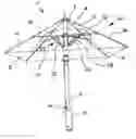
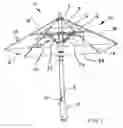
BRIEF DESCRIPTION OF THE DRAWINGSFIG. 1 is a perspective view of the apparatus according to an embodiment of the invention showing the pyramid shape of the open umbrella with a rectangular bottom.
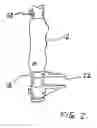
FIG. 2 is a perspective view of an adapter that can be attached to the handle or shaft of the umbrella so the umbrella can be attached to a stadium bench or a chair back.
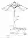
FIG. 3 is a perspective view of the umbrella attached to a stadium bench showing the telescoping shaft which permits the shaft to extend to a greater height.
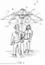
FIG. 4 is a perspective view of the umbrella showing how it would be used by two people sharing the umbrella.
BRIEF DESCRIPTION OF THE PRESENTLY PREFERRED AND ALTERNATE EMBODIMENTS OF THE INVENTIONPrior to proceeding with the more detailed description of the present invention it should be noted that, for the sake of clarity, identical components which have identical functions have been designated by identical reference numerals throughout the several views illustrated in the drawings.
The present invention provides an apparatus, generally designated 10, for providing protection for two people from rain, snow, sleet and harsh sunlight. The apparatus 10 comprises a shaft member 2 having an upper end and a lower end and having a rib connector 3 disposed on the shaft member 2 closely adjacent an upper end thereof. A transfer sleeve, generally designated 20, is mounted on the shaft member 2 for reciprocal movement along the shaft member 2 for opening and closing the apparatus. There is a cover portion 6 that is engageable with the rib connector 3 and extending outwardly therefrom. The cover portion 3 has a substantially rectangular shape and is formed from a predetermined material. Such predetermined material being a durable, lightweight material sufficiently strong to repel rain, snow and sleet. Such apparatus 10 has is a rib structure, generally designated 30, for connection with the rib connector 3, the cover portion 6 and the transfer sleeve 20. A tubular sleeve 4 is mounted on the upper end of the shaft member 2 intermediate the rib connector and the transfer sleeve and a handle member 12 is disposed on a bottom portion of the shaft member.
The rib structure 30 of such apparatus 10 includes a plurality of rib members 14 that are attached on a first end thereof to the rib connector 3 and connected on a second end thereof to said cover portion 6. Such plurality of rib members extend outwardly from the rib connector 3 to an outer edge of the cover portion 6. Such plurality of rib members 14 may also engage such cover portion 6 at various place along the plurality of rib members 14 to ensure that the cover portion 6 is attached snugly to the plurality of rib members 4.
Such rib structure 30 further includes a plurality of retracting ribs 16 that are engageable on a first end thereof with the upper portion of the transfer sleeve 20 and is engageable with the plurality of ribs 14 on a second end thereof. The plurality of retracting ribs 16 are engageable with the plurality of rib members 14 at substantially a mid point thereof. Thus when the transfer sleeve is retracted the retracting ribs 16 are retracted and the plurality of rib members 14 are retracted also which also retracts such cover portion 6.
As stated previously such bottom portion of cover portion 6 has a rectangular shape when the apparatus is in an open position and further the cover portion 6 has a pyramid shape when the apparatus is in an open position. By being rectangular the cover portion 6 provides better protection for the two parties that are using the apparatus 10 than is achieved with the conventional circular umbrella. FIG. 4 shows how the apparatus 10 would be used by two people sharing the umbrella.
The plurality of rib members 14 is four. That is, there is a rib for each corner of such pyramid shape of the cover portion 6. Further, the plurality of retracting ribs 16 is also four. Again there is one retracting rib 16 for each of plurality of ribs 14.
The predetermined material that is used for the cover portion 6 selected from plastic, nylon, cotton or combinations thereof. It is preferred that such predetermined material is plastic and, further, it is preferred that such plastic is vinyl. Such plastic can come in a variety of colors and/or various designs.
Such apparatus 10 further includes an adapter member 18 that is engageble with a bottom end of one of the handle member 12 and the shaft member 2 for attaching such apparatus 10 to a predetermined object so as to permit a hands free use of the apparatus. Such adapter member 18 includes an adjustable clamp 22 for attaching the apparatus to such predetermined object.
The adapter member 18 is removably engageable with one of the handle member 12 and the shaft member 2. Thus, such adapter 18 can be attached when needed and removed when not required. Such predetermined object is selected from one of a stadium bench or the back of a seat or chair. The adapter member 18 is engageable with one of such handle member 12 or shaft member 2 by means of snap on, slide on or clip on.
The shaft member 2 of such apparatus 10 is telescoping 24 which permits the shaft member 2 to be adjusted to a different height when it is used in the manner where the apparatus 10 is attached to a stadium bench as seen in FIG. 3. This permits the shaft to be lengthened so that the cover portion 6 will be above the users who will be sitting on the benches. When the apparatus is used as a normal umbrella being held by the user the shaft 2 is a normal length and there is no need to use the telescoping additional length of the shaft; however when the apparatus 10 is attached to the bench, as seen in FIG. 3, the additional shaft 2 length is required to raise the cover portion so that it will be above the heads of the users. Such adapter member 18 could be used to attach the apparatus 10 to a chair back or other items that could support the umbrella without the need for the user to hold it.
Thus, the telescoping shaft member 24 is designed to raise the apparatus to a sufficient height when the adapter 18 member is attached to whatever predetermined object is used.
The transfer sleeve 20 Of the apparatus 10 further includes a spring member 26 for biasing such apparatus 10 to an open position. When the apparatus is opened the spring member 26 opens the umbrella to the point where the upper end of the transfer sleeve 20 contacts the lower end of the tubular sleeve which stops the transfer sleeve 20 from opening any further. Button 32 on such shaft member 2 closely adjacent the handle member 12 releases such spring member so as to open such cover portion 6 easily.
Such plurality of retracting ribs 16 of the apparatus 10 further includes a plurality of supporting ribs 28 that are engageable with a lower end of the transfer sleeve 20 and with the plurality of retracting ribs 16 on a second end thereof for providing additional strength to the plurality of retracting ribs 16.
While a presently preferred embodiment and alternate embodiments of the present invention has been described in detail above, it should be understood that various other adaptations and/or modifications of the invention can be made by those persons who are particularly skilled in the art without departing from either the spirit of the invention or the scope of the appended claims.
Claims
I claim:1. An apparatus for providing protection for two people from rain, snow, sleet and harsh sunlight, said apparatus comprising;(a) a shaft member having an upper end and a lower end;
(b) a rib connector disposed on said shaft member closely adjacent an upper end thereof;
(c) a transfer sleeve mounted on said shaft member for reciprocal movement along said shaft member for opening and closing said apparatus;
(d) a cover portion engageable with said rib connector and extending outwardly therefrom, said cover portion having a substantially rectangular shape and formed from a predetermined material, said predetermined material being a durable, lightweight material sufficiently strong to repel rain, snow and sleet;
(e) a rib structure for connection with said rib connector, said cover portion and said transfer sleeve;
(f) a tubular sleeve mounted on said upper end of said shaft member intermediate said rib connector and said transfer sleeve; and
(g) a handle member disposed on a bottom portion of said shaft member.
2. The apparatus, according to claim 1, wherein said rib structure includes a plurality of rib members attached on a first end thereof to said rib connector and connected on a second end thereof to said cover portion, said plurality of rib members extending outwardly from said rib connector to an outer edge of said cover portion.
3. The apparatus, according to claim 2, wherein said rib structure further includes a plurality of retracting ribs engageable on a first end thereof with said upper portion of said transfer sleeve and engageable with said plurality of ribs on a second end thereof, said plurality of retracting ribs engageable with said plurality of ribs at substantially a mid point thereof.
4. The apparatus, according to claim 3, wherein a bottom portion of said cover portion has a rectangular shape when said apparatus is in an open position.
5. The apparatus, according to claim 4, wherein said cover portion has a pyramid shape when said apparatus is in an open position.
6. The apparatus, according to claim 5, wherein said plurality of ribs is four, a rib for each corner of said pyramid shape of said cover portion.
7. The apparatus, according to claim 6, wherein said plurality of retracting ribs is four.
8. The apparatus, according to claim 1, wherein said apparatus further includes an adapter member engageble with a bottom end of one of said handle member and said shaft member for attaching said apparatus to a predetermined object so as to permit a hands free use of said apparatus.
9. The apparatus, according to claim 8, wherein said adapter member includes an adjustable clamp for attaching said apparatus to said predetermined object.
10. The apparatus, according to claim 8, wherein said adapter member is removably engageable with one of said handle member and said shaft member.
11. The apparatus, according to claim 8, wherein said predetermined object is selected from one of a stadium bench and a chair back.
12. The apparatus, according to claim 8, wherein said adapter member is engageable with one of said handle member and said shaft member by means of one of snap on, slide on and clip on.
13. The apparatus, according to claim 1, wherein said predetermined material is selected from plastic, nylon, cotton or combinations thereof.
14. The apparatus, according to claim 13, wherein said predetermined material is plastic.
15. The apparatus, according to claim 14, wherein said plastic is vinyl.
16. The apparatus, according to claim 8, wherein said shaft member is telescoping, thus permitting said shaft member to be adjusted for different heights.
17. The apparatus, according to claim 16, wherein said telescoping shaft member is designed to raise said apparatus to a sufficient height when said adapter of said apparatus is attached to said predetermined object.
18. The apparatus, according to claim 1, wherein said transfer sleeve further includes a spring member for biasing said apparatus to an open position.
19. The apparatus, according to claim 3, wherein said plurality of retracting ribs further includes a plurality of supporting ribs engageable with a lower end of said transfer sleeve and with said plurality of retracting ribs on a second end thereof for providing additional strength to said plurality of retracting ribs.
Images & Drawings included:
Sources:
- United States Patent and Trademark Office - verify current appl. status at the USPTO↗
Similar patent applications:
- » 20200123802
Foldable tent comprising two umbrella structures - » 20200138154
Umbrella frame structure for two-fold inverted umbrella - » 20120037195
Umbrella with two belts - » 20070209691
Frame structure of an umbrella having two layers of cover - » 20080011343
Umbrella having two shafts - » 20070017562
Collapsible umbrella with two layers of cover - » 20060180188
Umbrella frame with two layers of covers - » 20080047595
Rib structure of a two-layer cover umbrella - » 20150351534
Two-tiered boot tray with umbrella drip tray stand - » 20110232705
Two-stage collapsing device for umbrella
Recent applications in this class:
- » 20250120482 2025-04-17
Automatic Wheelchair Umbrella Device - » 20230380556 2023-11-30
Vehicle-carrying leisure-purpose parasol rack - » 20230225468 2023-07-20
UMBRELLA MOUNT SYSTEM - » 20220022613 2022-01-27
Swingset frame shade - » 20210401132 2021-12-30
Universal pack-a-rella anchoring support - » 20210267328 2021-09-02
Parasol - » 20210219680 2021-07-22
Portable sunshade and slip-on mounting base - » 20200305563 2020-10-01
Umbrella holder - » 20200221835 2020-07-16
Canopy umbrella - » 20200000188 2020-01-02
Delta-shaped umbrella having a spring-loaded hub