Two-piece finger weight device
US20060287159A1
2006-12-21
11/154,028
2005-06-16
Abstract:
A two-piece finger weight device including a weight member and a strap for connecting the weight member to a finger. The strap is supported in one opening of the weight and after being disposed about a finger, it is secured to the weight member by interfitting openings in the straps with outwardly extending projections on the outer surface of the weight member. The weight member defines longitudinally extending openings of various sizes to accommodate weights of corresponding sizes to obtain the weight desired.
Inventors:
- Andrew S. Geller 2 🇺🇸 Lake Zurich, IL, United States
- Burton I. Geller 2 🇺🇸 Lake Zurich, IL, United States
Interested in similar patents?
Get notified when new applications in this technology area are published.
Classification:
A63B21/065 » CPC main
Exercising apparatus for developing or strengthening the muscles or joints of the body by working against a counterforce, with or without measuring devices; User-manipulated weights worn on user's body
A63B23/16 » CPC further
Exercising apparatus specially adapted for particular parts of the body for limbs, i.e. upper or lower limbs, e.g. simultaneously for upper limbs or related muscles, e.g. chest, upper back or shoulder muscles for hands or fingers
A63B23/14 IPC
Exercising apparatus specially adapted for particular parts of the body for limbs, i.e. upper or lower limbs, e.g. simultaneously for upper limbs or related muscles, e.g. chest, upper back or shoulder muscles for wrist joints
Description
BACKGROUND OF THE INVENTIONThe present invention relates to a device that is weighted and securable to a finger to assist in strengthening the finger during use of the finger. Such a weight is invaluable for sports usage, piano playing and other activities where fingers are in constant use and thus, in need of strengthening.
DESCRIPTION OF THE PRIOR ARTThere are a number of finger weight devices holding a plurality of weights on the market that have been used to strengthen fingers that are effective such as those cited in U.S. Pat. No. 7,570,41 to Hasfeld, U.S. Pat. No. 6,413,193 and in applicant's U.S. application entitled “Limb Weight Device” filed Nov. 29, 2004 and having Ser. No. 10/999,421. These devices while effective cannot be readily adjusted to be used on fingers of all sizes and when used are subject to becoming loose on a finger over time.
Similarly, while they can handle weights of varying sizes they make no provision for preventing expulsion of the weights when the finger goes through a strong forward motion such as throwing a baseball.
The simple and efficient design forming applicant's invention can be used on any size finger and the weights can quickly and easily be inserted. The finger weight assembly does not restrict circulation thus, allowing the wearer to use for an extended time without discomfort.
SUMMARY OF THE INVENTIONIn accordance with one embodiment of the invention there is illustrated a two piece finger weight including a weight receiving portion designed to fit on the top of a finger. The weight receiving portion in the illustrated embodiment which is by way of example only defines 3 longitudinally extending cylindrical holes (in the direction of the finger) into which are fitted cylindrical rod segments. The holes can extend all the way through or they can be blocked off at one end to prevent the weights from flying out when there is a sharp forward motion of the finger. Three are shown, but more or less can be provided as desired. The rod segments can be made of different materials depending on the finger weight desired. Examples of materials that can be used include tungsten and stainless steel.
To retain the weight holding device in position on a finger a separate strap is used. The strap has a strap portion that extends through an opening on one side of the weight holding device, which opening is defined by shoulders that receive the outwardly extending head portion of the strap. The strap portion defines spaced openings through which projections on the finger weight extends to secure the weight in position when the strap is tightened to the desired position by directing it around the finger and through a strap opening on the side opposite the location of the opening through which the strap is initially moved. When tightened in position, the respective strap openings are placed in interengaging projections with the upwardly extending projections on the weight holding member. The underside of the weight holding member and the strap are provided with a series of bumps or projections located adjacent to the strap openings that engage with grooves in the finger weight member adjacent the upwardly extending projections to prevent turning of the strap and finger weight relative to the finger.
The weigh holding member can be made of a variety of materials an example of which is a relatively hard plastic of 85-90 durometer and a strap of approximately 73 durometer for flexibility.
BRIEF DESCRIPTION OF THE DRAWINGSTo obtain a better understanding of the invention, reference is made to the accompanying drawings illustrating one embodiment of the invention in which:
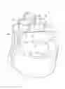
FIG. 1 is a perspective view of the novel finger weight device shown in the assembled position from one side thereof;
FIG. 2 is a side view of the device of FIG. 1 with the strap secured to the weight device free of a finger;
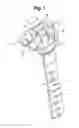
FIG. 3 is a perspective view of the embodiment shown in FIG. 2 showing the strap in a retained depending position;
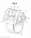
FIG. 4 is a perspective view of the finger weight device of FIG. 2; and
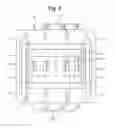
FIG. 5 is a plan view of the finger weight member;
FIG. 6 is a view similar to FIG. 1 of a second embodiment.
DETAILED DESCRIPTION OF THE DRAWINGSReferring to FIG. 1, there is illustrated the finger weight assemblage 10 showing a strap 12 secured in place on the weight member 14. The strap 12 includes a strap section 16 and a transversely extending head member 18. The strap head 18 is located on supports defined by recesses 20, 22 (see FIG. 5). The recesses 20, 22 are located adjacent the openings 24, 26 defined by the weight member 14 on both sides thereof. The strap head 18 is located in the recesses 20, 22 adjacent one of the openings 24, 26 and the strap section 16 is then wrapped around a finger and enters the other opening. The width of the strap section 16 is substantially equal to the width of the openings 24, 26 therefore. An assembled view (sans finger) is shown in FIG. 2.
Referring specifically to FIG. 3 there is shown the strap head 18 supported in the recesses 20, 22 and the strap section 16 is in position to be wrapped around a finger. As shown in FIG. 2, the weight member 14 is curved on its underside 27 to generally conform to the finger on which it is to be placed. The curve is slightly flatter than a finger and thus, does not completely encompass the finger when the strap is tightened so as to not totally impede the circulation flow through the finger. There are spherical shaped projections 29 on the underside 27 to aid in retaining the finger weight assembly in position relative to the finger. The finger weight member 14 is of a length to normally fit between the first and second joint or the second and third joint of a finger.
As best seen in FIGS. 1 and 2, the weight member 14 has an outward surface 42 of a roughly triangular configuration and includes in its central section outwardly extending generally rectangular projections 44 that are designed to interfit with similar openings 46 in the strap portion 16. The fitting relationship between the strap section 16 openings 46 and the projections 44 of the weight member 14 is best shown in FIG. 2. Specifically, the strap when in the finger wrapped position extends through the opening 24 around a finger and through the opening 26 in the finger weight member opposite to the opening 24 in which the strap head 18 is located and secured in placed by the interfitting projections 44 and strap openings 46. The number of projections can be varied as desired along with the corresponding strap openings. What is illustrated is by way of example only.
It is to be further noted that the weight member 14 defines outwardly extending flanges 48, 50 that guide the strap relative to the weight member 14 as the strap is wrapped into position. Located between the flanges 48, 50 and projections 44 and in the same general alignment are grooves 52, 54. These grooves 52, 54 are designed to receive generally semi-spherical projections or bumps 56 found on the inner surface of the strap 16 in parallel relationship to, but on opposite sides of the strap openings 46 (see FIG. 5) to assist in preventing the strap 16 from turning relative to the weight member 14. As seen in FIG. 5, the grooves 52, 54 are located at the openings 24, 26 on both sides of the weight member 14 to accommodate the bumps 56 on the strap.
The weight member 14 defines longitudinally extending (in the finger extending direction) cylindrical openings 28, 30, 32 for the receipt of cylindrical finger weights 34, 36, 38. The finger weights are in frictional engagement with the openings to retain them in position. In the illustrated embodiments, there are shown 3 openings, but this is by way of example only. There can be more or less as desired and can take different shapes. One or more weights can be inserted at any given time to vary the weight of the weight member as desired. Furthermore, the material of the weight can also be varied and two material examples that can be employed are stainless steel having an approximate weight of 10 grams/rod or tungsten having an approximate weight of 25 grams/rod.
The weight openings 28, 30, 32 shown in FIGS. 1, 2 and 5 do not extend all the way through in that the weight member 14 is formed with generally semi-spherical and covers 58. In the embodiment shown in FIGS. 3 and 6, the weight openings 28, 30, 32 extend completely through the weight member 14.
It is intended to cover by the appended claims all embodiments that fall within the true spirit and scope of the invention.
Claims
1. A finger weight device comprising a first member having at least one weight receiving portion, a strap for securing the weight to a finger, the weight defining means for supporting one end of the strap relative thereto and the strap and weight defining cooperating projections and openings for securing the strap to the weight when it is to be secured to a finger.
2. A finger weight device as set forth in claim 1 in which the weight member defines a strap opening on both sides thereof, at least one of said openings defining at least one adjacent recess for supporting for said one end of the strap, the strap is a separate member and defines a portion sized to extend through said opening and a head portion contacting said recess whereby said one end of said strap is supported in position relative to said weight member.
3. A finger weight device as set forth in claim 2 in which the unsupported end of said strap extends through the other opening and the projections are defined on an outer surface of said weight member, and the strap defines openings for receiving the projections whereby when the strap is secured relative to one opening and the other end of the strap extends through the other opening, the strap portion receives the projections in its spaced openings to secure the weight member in position on a finger.
4. A finger weight device as set forth in claim 3 in which the weight member defines outwardly extending flanges parallel to said projections to retain the strap relative thereto.
5. A finger weight device as set forth in claim 4 in which the projections are centrally spaced on the weight member and the weight member defines grooves extending parallel to said projections and the strap defines projections parallel to said spaced openings to engage said grooves to prevent turning of the strap relative to the weight member.
6. A finger weight device as set forth in claim 5 in which the weight member is arcuately shaped on its underside to generally conform to a finger.
7. A finger weight as set forth in claim 5 in which there are provided outwardly extending projections that are positioned to engage the finger when the weight is in position to help prevent the weight from moving relative to the finger.
8. A finger weight device as set forth in claim 6 in which the accurate surface includes end portions that do not contact said finger insuring that there is circulation through said finger.
9. A finger weight device as set forth in claim 6 in which the outer surface of said weight member is generally triangular in configuration and defines openings for receiving weights therein.
10. A finger weight device as set forth in claim 9 in which the openings extend longitudinally and generally parallel to the finger on which it is to be located.
11. A finger weight device as set forth in claim 9 in which the openings extend completely through the weight member.
12. A finger weight as set forth in claim 10 in which the openings are closed at one end to prevent the weights from leaving the weight member when the finger weight device is suddenly moved in the direction of the closed end.
13. A finger weight device as set forth in claim 2 in which the weight member is generally triangular in cross section and the openings located at each side of the weight member are of a width to restrain the elongated strap end, but permit the strap to be moved therethrough.
14. A finger weight device as set forth in claim 10 in which there are three longitudinally extending openings for receiving weights.
15. A finger weight device as set forth in claim 5 in which the side weight member openings are sized to closely receive the strap and the weight member defines recesses for the projections on the strap disposed adjacent the strap openings for receiving the strap projections.
16. A finger weight device comprising a first member having at least one weight receiving portion, a strap for securing the weight to a finger, the first member being arcuately shaped on its underside to generally conform to a finger, the outer surface being triangular in configuration and defining openings for receiving weights therein.
17. A finger weight device as set forth in claim 16 in which there are three longitudinally extending openings for receiving weights.
18. A finger weight device as set forth in claim 17 in which the openings are closed at one end to prevent the weights from leaving the weight member when the finger weight device is suddenly moved in the direction of the closed end.
Images & Drawings included:


Sources:
- United States Patent and Trademark Office - verify current appl. status at the USPTO↗
Similar patent applications:
- » 20060287160
Two-piece finger weight device II
Recent applications in this class:
- » 20250152992 2025-05-15
WEIGHTED VEST - » 20250121245 2025-04-17
WEIGHTED APPAREL SYSTEMS AND METHODS FOR USE IN PERSONAL FITNESS - » 20250121244 2025-04-17
WEIGHTED VEST - » 20250114656 2025-04-10
WEIGHTED VEST - » 20250108246 2025-04-03
WEIGHTED ARTICLE OF APPAREL WITH ADJUSTABLE FIT AND METHOD OF MANUFACTURING THE SAME - » 20250099800 2025-03-27
WEIGHT-BEARING BRACELET - » 20250065178 2025-02-27
Exercise Device Targeting Anterior Tibialis Muscles & Method Of Use - » 20250041649 2025-02-06
FOOT DUMBBELL EXERCISER - » 20250041648 2025-02-06
Weight exercise system and apparatus - » 20240390724 2024-11-28
WEIGHTED COMPRESSION SLEEVES