Two-piece finger weight device II
US20060287160A1
2006-12-21
11/344,392
2006-01-30
Abstract:
A two piece finger weight device including a weight member and a strap for connecting the weight member to a finger. The strap is supported in one opening of the weight. After being disposed about a finger and over an arcuate surface defined by the weight member between two flanges, it is secured to the weight member by interfitting openings in the strap with outwardingly extending projections provided on the arcuate surface. The strap is further retained in position by a hinged member secured to one flange member, which hinged member is extended over the strap on the arcuate surface and secured to a projection located on the other flange.
Inventors:
- Andrew S. Geller 2 🇺🇸 Lake Zurich, IL, United States
- Burton I. Geller 2 🇺🇸 Lake Zurich, IL, United States
Interested in similar patents?
Get notified when new applications in this technology area are published.
Classification:
A63B21/065 » CPC further
Exercising apparatus for developing or strengthening the muscles or joints of the body by working against a counterforce, with or without measuring devices; User-manipulated weights worn on user's body
A63B21/4019 » CPC further
Exercising apparatus for developing or strengthening the muscles or joints of the body by working against a counterforce, with or without measuring devices; Interfaces with the user related to strength training; Details thereof; Arrangements for attaching the exercising apparatus to the user's body, e.g. belts, shoes or gloves specially adapted therefor to the upper limbs to the hand
A63B23/16 » CPC main
Exercising apparatus specially adapted for particular parts of the body for limbs, i.e. upper or lower limbs, e.g. simultaneously for upper limbs or related muscles, e.g. chest, upper back or shoulder muscles for hands or fingers
A63B23/14 IPC
Exercising apparatus specially adapted for particular parts of the body for limbs, i.e. upper or lower limbs, e.g. simultaneously for upper limbs or related muscles, e.g. chest, upper back or shoulder muscles for wrist joints
Description
BACKGROUND OF THE INVENTIONThe present invention relates to a device that is weighted and securable to a finger to assist in strengthening the finger during use of the finger. Such a weight is invaluable for sports usage, piano playing and other activities where fingers are in constant use and thus, in need of strengthening.
DESCRIPTION OF THE PRIOR ARTThere are a number of finger weight devices holding a plurality of weights on the market that have been used to strengthen fingers that are effective such as those cited in U.S. Pat. No. 757,041 to Hasfeld, U.S. Pat. No. 6,413,193 and in applicant's U.S. application entitled “Limb Weight Device” filed Nov. 29, 2004 and having Ser. No. 10/999,421. These devices while effective cannot be readily adjusted to be used on fingers of all sizes and when used are subject to becoming loose on a finger over time.
Similarly, while they can handle weights of varying sizes they make no provision for preventing expulsion of the weights when the finger goes through a strong forward motion such as throwing a baseball.
The simple and efficient design forming applicant's invention can be used on any size finger and the weights can quickly and easily be inserted. The finger weight assembly does not restrict circulation thus allowing the wearer to use for an extended time without discomfort.
This application is a continuation-in-part of Ser. No. 11/154,028 filed Jun. 16, 2005 entitled “Two-Piece Finger Weight Device” and overcomes the disadvantages set forth above and provides additional novel features that are disclosed and claimed herein.
SUMMARY OF THE INVENTIONIn accordance with the present invention there is illustrated a two piece finger weight including a weight receiving portion designed to fit on the top of a finger. The weight receiving portion in the illustrated embodiment which is by way of example only defines 3 longitudinally extending cylindrical holes (in the direction of the finger) into which are fitted cylindrical rod segments. The holes can extend all the way through and in the illustrated embodiment they are blocked off at one end to prevent the weights from flying out when there is a sharp forward motion of the finger. Three are shown, but more or less can be provided as desired. The rod segments can be made of different materials depending on the finger weight desired. Examples of materials that can be used include tungsten and stainless steel.
To retain the weight holding device in position on a finger a separate strap is used. The strap has a strap portion that extends through an opening on one side of the weight holding device. The weight holding device defines areas such as shoulders adjacent the opening that receive the outwardly extending head portion of the strap to retain the strap relative to the weight holding device. The strap portion defines spaced openings through which projections on the finger weight extend to secure the weight in position when the strap is tightened to the desired position by directing it around the finger and through a strap opening on the side opposite the location of the opening through which the strap is initially moved. The strap head is held in position upon engagement with the aforementioned shoulders adjacent said opening. When tightened in position, the respective strap openings are placed in interengaging position with the upwardly extending projections on the weight holding member.
In the illustrated embodiment the strap receiving portion has a generally arcuate shape recess that has two outwardly extending generally bulbous projections that engage the strap. The underside of the weight holding member and the strap are provided with a series of bumps or projections that engage with the finger when secured thereto to prevent turning of the strap and finger weight relative to the finger.
In addition, the weight holding member includes side members or flanges that are spaced apart to define the arcuate strap receiving portion of the weight member. Extending outwardly from one of the side members and hinged thereto is a member having an opening therein. The member is designed to extend over the arcuate weight strap receiving portion to retain the strap in place thereon.
The opening in the hinge member interfits with a projection extending upwardly from the other side member to lock the hinge member in position when disposed over the strap secured to the weight member.
The weigh holding member can be made of a variety of materials an example of which is a relatively hard plastic of 85-90 durometer and a strap of approximately 73 durometer for flexibility. With the instant design, the weight holding member can be easily molded.
BRIEF DESCRIPTION OF THE DRAWINGSTo obtain a better understanding of the invention, reference is made to the accompanying drawings illustrating the invention in which:
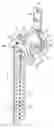
FIG. 1 is a perspective view of the novel finger weight device showing the strap in a retained depending position;
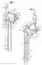
FIG. 2 is a perspective view of the finger weight device of FIG. 1 rotated to show the configuration of the other side of the strap;
FIG. 3 is a perspective view of the novel finger weight device without the strap;
FIG. 4 is a view similar to FIG. 3, but rotated to show the bottom of the finger weight member; and
FIG. 5 is a perspective view of the finger weight device containing weights and the strap secured to the weight device free of a finger;
DETAILED DESCRIPTION OF THE DRAWINGSReferring to FIG. 1, there is illustrated the finger weight assemblage 10 showing a strap 12 secured in place on the weight member 14. The strap 12 includes a strap section 16 and a transversely extending head member 18. The strap head 18 is located on shoulders or support areas 20,22 defined by the weight device. (See FIG. 3). The support areas 20, 22 are located adjacent the openings 24, 26 defined by the weight member 14 on both sides thereof. The strap head 18 is supported on the areas 20, 22 adjacent one of the openings 24, 26 and the strap section 16 is then wrapped around a finger and enters the other opening. The width of the strap section 16 is substantially equal to the width of the openings 24, 26 therefore. There are inwardly extending flanges 25, 27 that define the openings 24, 26. The flanges 25, 27 also serve to prevent the strap from moving away from the weight device. An assembled view of the weight assemblage (sans finger) is shown in FIG. 5.
Referring specifically to FIG. 1 there is shown the strap head 18 supported on the areas 20, 22 and the strap section 16 is in position to be wrapped around a finger. As shown in FIG. 4, the weight member 14 is curved on its underside 29 to generally conform to the finger on which it is to be placed. The curve is slightly flatter than a finger and thus, does not completely encompass the finger when the strap is tightened so as to not totally impede the circulation flow through the finger. There are spherical shaped projections 31 on the underside 29 to limit the movement of the finger weight assembly relative to the finger. The finger weight member 14 is of a length to normally fit between the first and second joint or the second and third joint of a finger.
As best seen in FIG. 3, the weight member 14 has an outer surface of a roughly triangular configuration. This is defined by side or flange members 32, 34. Located intermediate the side flanges is an arcuate shaped strap receiving portion 36. The width of the arcuate section 36 is constructed and arranged to receive the strap portion 16 after it is wrapped around a finger. The side flanges 32, 34 extend outwardly to retain the strap therebetween. Located on opposite sides of the arcuate surface are outwardly extending bulb-shaped projections 38, 40. The projections are sized to be received in openings 46 in the strap after the strap has been tightly wrapped around a finger. Specifically the strap when in the finger-wrapped position extends through the opening 24 around a finger and through the opening 26 in the finger weight member opposite to the opening 24 in which the strap head 18 is located and secured in placed by the interfitting projections 38, 40 and strap openings 46. While 2 are illustrated, the number of projections can be varied as desired along with the corresponding strap openings. What is illustrated is by way of example only.
In accordance with this invention, a member 48 is hinged to the side flange 32. The size and shape of this member 48 is such that when it is hinged over the strap portion located on the arcuate surface 36 as shown in FIG. 5, the strap is prevented from moving away from the arcuate support. To secure the member 48 in position the side flange 34 is provided with an upstanding projection 50 that fits into the opening 52 formed in the hinged member 48. It is to be noted that the strap portion 16 has formed on its underside generally semi-spherical projections or bumps 56 in parallel relationship to, but on opposite sides of the strap openings 46 (see FIG. 2) to assist in preventing the strap 16 from turning relative to the weight member 14.
The weight member 14 defines longitudinally extending (in the finger extending direction) cylindrical openings 58, 60, 62 for the receipt of cylindrical finger weights 64, 66, 68. The finger weights are in frictional engagement with the openings to retain them in position. In the illustrated embodiments, there are shown 3 openings, but this is by way of example only. There can be more or less as desired and can take different shapes. One or more weights can be inserted at any given time to vary the weight of the weight member as desired. Furthermore, the material of the weight can also be varied and two material examples that can be employed are stainless steel having an approximate weight of 10 grams/rod or tungsten having an approximate weight of 25 grams/rod.
The weight openings 28, 30, 32 shown in FIGS. 1, 2 and 5 do not extend all the way through in that the weight member 14 is formed with generally semi-spherical end covers 70.
It is intended to cover by the appended claims all embodiments that fall within the true spirit and scope of the invention.
Claims
1. A finger weight device comprising a member having at least one weight receiving portion, a strap for securing the weight to a finger, the weight member defining means for supporting one end of the strap relative thereto, the member having a recess defined by flanges in which the strap is positioned, the strap and recess defining cooperating projections and openings for securing the strap to the member when the device is to be connected to a finger, extending outwardly from one of said flanges is a hinge member defining an opening and from the other flange is a connection which opening and connection are constructed and arranged to interfit to secure the hinge member to the other flange to retain the strap in the recess to prevent the strap from dislodging during use of the weight device.
2. A finger weight device as set forth in claim 1 in which the recess is arcuately shaped.
3. A finger weight device as set forth in claim 2 in which the projections are located on opposite sides of the hinge member.
4. A finger weight device as set forth in claim 3 in which the projections are bulb-shaped.
5. A finger weight device as set forth in claim 1 in which the weight member means for supporting one end of the strap relative thereto includes a strap opening on both sides thereof and the weight member defines areas adjacent said opening for supporting the strap relative to the weight member, said strap includes a main portion that extends through said opening.
6. A finger weight device as set forth in claim 1 which the side opposite the recess is arcuately shaped to generally conform to a finger.
7. A finger weight as set forth in claim 6 in which there are provided outwardly extending projections from said arcuate surface to help prevent the weight device from moving relative to the finger when in engagement therewith.
8. A finger weight device as set forth in claim 7 in which the arcuate surface includes end portions that do not contact said finger insuring that there is circulation through said finger.
9. A finger weight device as set forth in claim 1 in which the outer surface of said weight member is generally triangular in configuration and defines openings for receiving weights therein.
10. A finger weight device as set forth in claim 9 in which the openings extend longitudinally and generally parallel to the finger on which it is to be located.
11. A finger weight as set forth in claim 10 in which the openings are closed at one end to prevent the weights from leaving the weight member when the finger weight device is suddenly moved in the direction of the closed end.
12. A finger weight device as set forth in claim 11 in which there are three longitudinally extending openings for receiving weights.
Images & Drawings included:


Sources:
- United States Patent and Trademark Office - verify current appl. status at the USPTO↗
Recent applications in this class:
- » 20250153000 2025-05-15
GRIP TRAINING SYSTEM - » 20250128121 2025-04-24
Portable Hangboard for Grip and Finger Strength Training. - » 20250082993 2025-03-13
EXERCISE BARS WITH MULTIPLE GRIP MEMBERS - » 20250073528 2025-03-06
CLIMBING PINCH TRAINING MACHINE - » 20250073527 2025-03-06
Upper Limb Rehabilitation Device and Method of Its Application for Sarcopenia - » 20250025747 2025-01-23
FINGER EXERCISING DEVICE AND SYSTEM FOR THE TRAINING, WARMING UP, AND/OR REHABILITATION OF MUSCLES, TENDONS, AND PULLEYS OF THE PHALANGES AND METHOD OF DETERMINING ADHESION FOR CLIMBING - » 20250001249 2025-01-02
MULTIFUNCTIONAL HAND GRIP EXERCISER - » 20240316401 2024-09-26
FINGER EXERCISE DEVICE - » 20240278069 2024-08-22
UPPER LIMB REHABILITATION APPARATUS FOR BOTH ARMS EXERCISE - » 20240123282 2024-04-18
Hand Gripper