Machining apparatus
US20090106962A1
2009-04-30
12/199,930
2008-08-28
✅ Patent granted
US 8,136,214 B2
2012-03-20
-
-
Erica E Cadugan
2030-08-25
Abstract:
A machining apparatus (1) for machining rotation-symmetrical workpieces (10), comprising a machine frame (4), which has a vertical front face (11), further comprising at least one vertical workpiece spindle (2) that is arranged on the front face (11) and can be driven rotatorily,
comprising at least two tool holders (3 and 3a), which are arranged on the front face (11) displaceably horizontally and vertically by means of compound slides (5 and 5a),
further comprising a conveyor (9) for workpieces (10), and a loading and unloading device (13), wherein the workpieces (10) can be transported by the conveyor (9) in a direction parallel to the front face (11).
Assignee:
- EMAG HOLDING GMBH 33 🇩🇪 Salach, Germany
Interested in similar patents?
Get notified when new applications in this technology area are published.
Classification:
B23B3/167 » CPC main
General-purpose turning-machines or devices, e.g. centre lathes with feed rod and lead screw; Sets of turning-machines; Turret lathes for turning individually-chucked workpieces lathe with two or more toolslides carrying turrets
B23B3/06 » CPC further
General-purpose turning-machines or devices, e.g. centre lathes with feed rod and lead screw; Sets of turning-machines Turning-machines or devices characterised only by the special arrangement of constructional units
B23Q7/045 » CPC further
Arrangements for handling work specially combined with or arranged in, or specially adapted for use in connection with, machine tools, e.g. for conveying, loading, positioning, discharging, sorting by means of grippers using a tool holder as a work-transporting gripper
B23Q39/023 » CPC further
Metal-working machines incorporating a plurality of sub-assemblies, each capable of performing a metal-working operation the sub-assemblies being capable of being brought to act at a single operating station with a plurality of toolheads per workholder, whereby the toolhead is a main spindle, a multispindle, a revolver or the like with same working direction of toolheads on same workholder simultaneous working of toolheads
B23Q2039/004 » CPC further
Metal-working machines incorporating a plurality of sub-assemblies, each capable of performing a metal-working operation Machines with tool turrets
B23Q2039/008 » CPC further
Metal-working machines incorporating a plurality of sub-assemblies, each capable of performing a metal-working operation Machines of the lathe type
Y10T29/5114 » CPC further
Metal working; Plural diverse manufacturing apparatus including means for metal shaping or assembling; Type of machine; Lathe Lathe and tool
Y10T29/5124 » CPC further
Metal working; Plural diverse manufacturing apparatus including means for metal shaping or assembling with means to feed work intermittently from one tool station to another
Y10T29/5153 » CPC further
Metal working; Plural diverse manufacturing apparatus including means for metal shaping or assembling with turret mechanism Multiple turret
Y10T82/2508 » CPC further
Turning; Lathe with tool turret
Y10T82/2511 » CPC further
Turning; Lathe Vertical
Y10T82/2514 » CPC further
Turning; Lathe with work feeder or remover
Y10T82/2524 » CPC further
Turning; Lathe Multiple
B23B27/00 IPC
Tools for turning or boring machines ; Tools of a similar kind in general; Accessories therefor
B23P23/00 IPC
Machines or arrangements of machines for performing specified combinations of different metal-working operations not covered by a single other subclass
B23Q7/00 IPC
Arrangements for handling work specially combined with or arranged in, or specially adapted for use in connection with, machine tools, e.g. for conveying, loading, positioning, discharging, sorting
Description
The invention relates to a machining apparatus for machining rotation-symmetrical workpieces, comprising a vertical workpiece spindle and at least two tool holders according to the preamble of claim 1.
A machining apparatus of this type is known from EP 1 574 273. In this machine, the workpiece spindle is carried on the machine frame for displacement on two axes (X, Z). It operates based on the pick-up method, which is to say it seizes the workpieces from a conveyor, feeds them to the machining operation, and subsequently sets them down again. The two turrets can each be displaced in axial direction X or Z. The workpieces are fed in on the one machine side and removed on the opposite side.
It is the object of the present invention to create a compact, space-saving machining apparatus. It is also the aim of the invention to configure a machining apparatus such that workpiece transport can be carried out in an optimized and cost-effective manner.
This object is attained by a machining apparatus with the characteristics of claim 1.
An advantageous aspect of the invention is the feeding of the workpieces from the operator side in the case of a machining apparatus having a vertical working spindle. Since lateral conveyor belts are eliminated, a space-saving machine design becomes possible. In addition, the machining apparatus can also be set up in a particularly compact manner. The short distances during loading and unloading can be viewed as a further advantage of this solution. As a result, nonproductive times during which no machining of workpieces occurs can be significantly reduced.
Additional characteristics and advantages of the invention will be apparent from the following description based on the illustrated embodiments.
Therein:
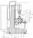
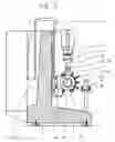
FIG. 1 is a front view of the machining apparatus according to the invention;
FIGS. 2a and 2b are detailed views according to FIG. 1;
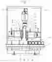
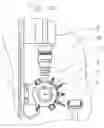
FIG. 3 is a side view
FIGS. 4a and 4b are detailed illustrations according to FIG. 3;
FIGS. 5a and 5b how the gripping operation;
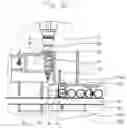
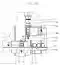
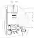
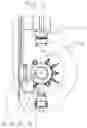
FIGS. 6 and 7 are advantageous embodiments in detail views like FIG. 3.
FIG. 1 shows a machining apparatus 1 for machining rotation-symmetrical workpieces 10, where for better clarity parts that are not essential for the invention, particularly details of the drive mechanism, the controller and the housing, have been omitted. The machining apparatus 1 comprises a vertical workpiece spindle 2 mounted on a machine frame 4 in a stationary manner, and two tool holders 3 and 3a. The two tool holders 3 and 3a have turrets displaceable on respective compound slides 5 and 5a in a horizontal direction (X) and vertical direction (Z) on the machine frame 4. Turret disks 6 and 6a with respective tools 7 and 7a are rotatably supported about respective horizontal pivot axes 8 and 8a. A conveyor 9 delivers workpiece blanks 10 to a workpiece intake station 14 and removes the machined workpieces. In an advantageous embodiment, the conveyor 9 is a continuously moving endless conveyor belt that continuously pushes the workpieces 10 against a stop 15 in the workpiece intake station 14. The detail views of FIGS. 2a and 2b show the loading process. The start of the loading process is shown in FIG. 2a. There, a grab 12 of the tool holder 3 seizes the finished workpiece 10 in the workpiece spindle 12. Vertical movement of the compound slide 5 and simultaneous pivoting of the turret disk 6 about the pivot axis 8, sets the workpiece 10 down on the conveyor 9. The compound slide 5 also moves horizontally to allow the workpiece spindle 2 to be reloaded at the same time. For loading purposes, the grab 12a grips a workpiece blank 10a in the intake station 14. The movements of the compound slide 5a and the pivoting movement of the turret disk 6a occur synchronously with the movements during unloading but in the opposite direction. FIG. 2b shows the completed loading process: The finished workpiece 10a has been set down on the conveyor 9 and the workpiece blank 10 has been fitted to the workpiece spindle 2. After removing the workpiece 10a from the workpiece intake station 14, the next workpiece 10b has been moved by the conveyor 9 to the stop 15.
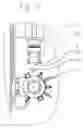
FIG. 3 shows the machining apparatus 1 in a side view. The machine frame 4 comprises a wider lower frame part 17 and a narrower upper frame part 18 projecting upward therefrom, the upper part having a vertical front face 11. The workpiece spindle 2 is fixedly attached to the vertical front face 11, and the tool holders 3 and 3a can be displaced horizontally and vertically by means of the compound slides 5 and 5a. In an advantageous embodiment, the loading and unloading device 13 is integrated into the tool holders 3 and 3a. For handling the workpieces 10, the tool holders 3 and 3a are provided with the respective grabs 12 and 12a. The conveyor 9 extends parallel to the front face 11. Compared to the state of the art, the distances for loading and unloading are particularly short because the workpiece intake station 14 can be very close to the workpiece spindle 2. As a result, nonproductive time during which no machining of workpieces occurs can be significantly reduced. The short transport distances during loading and unloading are clearly apparent in the side views according to FIGS. 4a and 4b. The grab 12 seizes the workpiece 10, and with a vertical movement of the compound slide 5 and simultaneous pivoting of the turret disk 6 about the pivot axis 8 by a pivot angle of 90°, the workpiece 10 is set down on the conveyor 9. In order to maneuver the grab 12 into and out of the workpiece 10 located on the conveyor 9, both parts must be moved relative to each other in one direction orthogonal to the vertical wall 11. To this end, according to FIG. 5a, the grab 12 can telescope and perform the corresponding lifting motion in the direction of the double arrow 19 if necessary. Alternatively, in the embodiment according to FIG. 5b a pusher element 20 is provided that pushes the workpiece 10 onto the grab 12.
In the embodiment shown in FIG. 6, horizontal travel of the workpiece 10 and the grab 12 can be eliminated by providing the conveyor 9 directly underneath the tool holder 3. Here the workpiece 10 is moved vertically downward onto the conveyor 9 following a pivoting movement of the turret disk 6 about the pivot axis 8 through an angle β of 180°. For maneuvering the workpiece 10 in and out, the compound slide 5 is moved vertically.
In a further advantageous embodiment according to FIG. 7, the conveyor 9 is positioned between the workpiece spindle 2 and the tool holder 3. The conveyor 9 can open downward. The workpieces 10 are inserted through an opening 21 into the workpiece spindle 2 by the pusher 20. The embodiment has the advantage that the moving conveyor 9 needs even less space.
LIST OF REFERENCE NUMERALS
| 1 | Machining apparatus | |
| 2 | Workpiece spindle | |
| 3 3a | Tool holder | |
| 4 | Machine frame | |
| 5 5a | Compound slide | |
| 6 6a | Turret disk | |
| 7 7a | Tools | |
| 8 8a | Pivot axis | |
| 9 | Conveyor | |
| 10 10a | Workpiece | |
| 11 | Front face | |
| 12 12a | Grab | |
| 13 | Loader/unloader | |
| 14 | Intake station | |
| 15 | Stop | |
| 16 | Lifting device | |
| 17 | Lower frame part | |
| 18 | Upper frame part | |
| 19 | Double arrow | |
| 20 | Pusher | |
| 21 | Opening | |
| α β | Pivot angle | |
Claims
1. A machining apparatus for machining rotation-symmetrical workpieces, comprising a machine frame, which has a vertical front face, further comprising at least one vertical workpiece spindle that is arranged on the front face and can be driven rotatorily,
comprising at least two tool holders, which are arranged on the front face displaceably horizontally and vertically by means of compound slides, also comprising a conveyor for workpieces, and a loading and unloading device
wherein
the workpieces can be transported by the conveyor in a direction parallel to the front face.
2. The machining apparatus according to claim 1 wherein the workpiece spindle is arranged on the machine frame in a stationary manner and that the conveyor and the loading and unloading device are arranged beneath the workpiece spindle.
3. The machining apparatus according to claim 2 wherein the conveyor and the loading and unloading device are arranged in front of the vertical front face, viewed from the operator side.
4. A machining apparatus according to claim 1 wherein the tool holders are configured as turrets and that the turret disks are supported pivotally about horizontal pivot axes.
5. The machining apparatus according to claim 4 wherein the turrets each have a grab for handling the workpieces.
6. The machining apparatus according to claim 5 wherein it has a workpiece intake station and that the turrets can be displaced in the active regions of both the workpiece intake station and the workpiece spindle.
7. The machining apparatus according to claim 6 wherein the workpieces can be transported from the workpiece intake station to the workpiece spindle by means of the grabs by displacing the compound slides and pivoting the turret disks about the horizontal pivot axes.
8. A machining apparatus according to claim 1, further comprising
a continuously conveying conveyor wherein a stop is provided for positioning the workpieces in the workpiece intake station.
9. The machining apparatus according to claim 7 wherein the workpieces are transported horizontally on the conveyor and reach a vertical position after being received by the grabs as a result of pivoting the turret disks by 90°, or vice versa from a horizontal to a vertical position.
10. The machining apparatus according to claim 8 wherein for receiving the workpiece the grabs and the workpieces can be moved relative to each other in a direction orthogonal to the front face.
11. A machining apparatus according to claim 1 wherein the conveyor transports the workpieces into a position directly beneath the workpiece spindle wherein a lifting device is provided for inserting the workpieces into the workpiece spindle.
12. An apparatus for machining rotation-symmetrical workpieces, the apparatus comprising:
a machine frame having a vertical front face;
a vertical spindle mounted on the frame in front of the front face and rotatable about a vertical axis;
two tool holders;
respective compound slides on the front face carrying the tool holders and each displaceable horizontally and vertically; and
conveyor means for displacing workpiece blanks parallel to the face to an intake position adjacent the spindle and for displacing machined workpieces away from the frame also parallel to the face.
13. The machining apparatus defined in claim 12 wherein the spindle is only rotatable about the spindle axis and is substantially fixed against other movement on the frame.
14. The machining apparatus defined in claim 12 wherein the conveyor is a continuous belt having an upper stretch extending horizontally past the frame underneath the spindle.
15. The machining apparatus defined in claim 14, further comprising
a stop above the upper stretch and defining the intake station.
16. The machining apparatus defined in claim 14 wherein the conveyor upper stretch is directly underneath the spindle aligned with the spindle axis and is openable so the workpieces can pass vertically through the upper stretch, the turrets and slides being in turn underneath the conveyor.
17. The machining apparatus defined in claim 12 wherein each holder is a turret rotatable about a respective horizontal turret axis on the respective slide.
18. The machining apparatus defined in claim 17 wherein each turret carries offset from the respective turret axis a respective grab.
Images & Drawings included:

Sources:
- United States Patent and Trademark Office - verify current appl. status at the USPTO↗
Similar patent applications:
- » 20220040795
Machining apparatus for laser machining a workpiece, set of parts for a machining apparatus for laser machining a workpiece and method for laser machining a workpiece using such machining apparatus - » 20150248125
Control device for machining apparatus, machining apparatus, and correction method of machining data - » 20230302543
METHOD FOR PRESSING TAILSTOCK OF MACHINING APPARATUS, MACHINING APPARATUS, AND COMPUTER-READABLE STORAGE MEDIUM - » 20230061659
HANDHELD LASER MACHINING APPARATUS FOR MACHINING A WORKPIECE, AND FUNNEL FOR A HANDHELD LASER MACHINING APPARATUS - » 20200038999
CONTROL DEVICE FOR LASER MACHINING APPARATUS, AND LASER MACHINING APPARATUS - » 20150224601
Method for the recuperation of unused optical radiation energy of an optical machining apparatus, recuperation apparatus and optical machining apparatus - » 20200039147
Control device for laser machining apparatus, and laser machining apparatus - » 20200038992
Control device for laser machining apparatus, and laser machining apparatus - » 20130268110
Machining error calculation apparatus, machining error calculation method, machining control apparatus and machining control method thereof - » 20220001489
Laser machining apparatus, method for setting machining conditions, and control device for laser machining apparatus
Recent applications in this class:
- » 20170072473 2017-03-16
Machine tool provided with tool post - » 20140298961 2014-10-09
Machine tool - » 20070068350 2007-03-29
NC automatic lathe - » 20060048614 2006-03-09
Vertical lathe
Recent applications for this Assignee:
- » 20160346894 2016-12-01
Dual-spindle grinding machine - » 20160278169 2016-09-22
Inductive hardening machine - » 20160023316 2016-01-28
Dual-spindle machining apparatus - » 20150018179 2015-01-15
Method and apparatus for changing tools - » 20140326114 2014-11-06
Double-spindle machining apparatus - » 20140157559 2014-06-12
Machining apparatus - » 20140094097 2014-04-03
Dual-spindle grinder - » 20140079500 2014-03-20
Machining apparatus with chip shield - » 20140030969 2014-01-30
Grinding disk and apparatus - » 20130340242 2013-12-26
Method and apparatus for complete machining of a shaft-shaped workpiece