Structure of LED Radiator
US20100218915A1
2010-09-02
12/380,514
2009-03-02
Abstract:
The improved structure of LED radiator comprises a radiator comprising with a better heat-dissipating plate bended through the machine as plurality of continuously arranged bottom area, side areas and top area. The length of the top area and the bottom area is the same. The top and the bottom areas are respectively vertical with the side area. The length of each side area is longer than each top and bottom area.
Interested in similar patents?
Get notified when new applications in this technology area are published.
Classification:
F21V29/76 » CPC main
Protecting lighting devices from thermal damage; Cooling or heating arrangements specially adapted for lighting devices or systems; Cooling arrangements characterised by passive heat-dissipating elements, e.g. heat-sinks with fins or blades with essentially identical parallel planar fins or blades, e.g. with comb-like cross-section
F21V29/717 » CPC further
Protecting lighting devices from thermal damage; Cooling or heating arrangements specially adapted for lighting devices or systems; Cooling arrangements characterised by passive heat-dissipating elements, e.g. heat-sinks using a combination of separate elements interconnected by heat-conducting means, e.g. with heat pipes or thermally conductive bars between separate heat-sink elements using split or remote units thermally interconnected, e.g. by thermally conductive bars or heat pipes
F28F1/128 » CPC further
Tubular elements; Assemblies of tubular elements; Tubular elements and assemblies thereof with means for increasing heat-transfer area, e.g. with fins, with projections, with recesses the means being only outside the tubular element consisting of zig-zag shaped fins Fins with openings, e.g. louvered fins
F28F1/325 » CPC further
Tubular elements; Assemblies of tubular elements; Tubular elements and assemblies thereof with means for increasing heat-transfer area, e.g. with fins, with projections, with recesses the means being only outside the tubular element and extending transversely the means having portions engaging further tubular elements Fins with openings
H01L21/4882 » CPC further
Processes or apparatus adapted for the manufacture or treatment of semiconductor or solid state devices or of parts thereof; Manufacture or treatment of semiconductor devices or of parts thereof the devices having at least one potential-jump barrier or surface barrier, e.g. PN junction, depletion layer or carrier concentration layer; Manufacture or treatment of parts, e.g. containers, prior to assembly of the devices, using processes not provided for in a single one of the subgroups -; Conductive parts; Bases, plates or heatsinks Assembly of heatsink parts
H01L23/3672 » CPC further
Details of semiconductor or other solid state devices; Arrangements for cooling, heating, ventilating or temperature compensation ; Temperature sensing arrangements; Selection of materials, or shaping, to facilitate cooling or heating, e.g. heatsinks; Cooling facilitated by shape of device Foil-like cooling fins or heat sinks
F21Y2115/10 » CPC further
Light-generating elements of semiconductor light sources Light-emitting diodes [LED]
F28D15/02 » CPC further
Heat-exchange apparatus with the intermediate heat-transfer medium in closed tubes passing into or through the conduit walls ; Heat-exchange apparatus employing intermediate heat-transfer medium or bodies in which the medium condenses and evaporates, e.g. heat pipes
F28F2215/12 » CPC further
Fins with U-shaped slots for laterally inserting conduits
H01L2924/0002 » CPC further
Indexing scheme for arrangements or methods for connecting or disconnecting semiconductor or solid-state bodies as covered by; Technical content checked by a classifier Not covered by any one of groups , and
H01L2924/00 » CPC further
Indexing scheme for arrangements or methods for connecting or disconnecting semiconductor or solid-state bodies as covered by
F28F7/00 IPC
Elements not covered by group , or
Description
BACKGROUND OF THE INVENTION
1. Field of the Invention
The present invention is related with the improved structure of LED radiator, especially for a radiator comprises with a better heat-dissipating plate bended through the machine as plurality of continuously arranged bottom area, side areas and top area. Because of the fast continuously caulking method for forming the radiator, it speeds the production, saves the time for dismantling and lowers the cost. It is very competitive and has economical efficiency.
2. Description of the Related Art
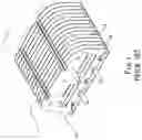
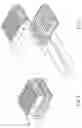
The prior invention as shown in FIGS. 1 and 2, the radiator comprises each heat-dissipating chip dismantled one after one by hand. Each top end of the heat-dissipating chip has a top spacer and the bottom end of the heat-dissipating chip has a bottom spacer. A through hole is set on the corner between the top spacer and the heat-dissipating chip and between the bottom spacer and the heat-dissipating chip. When two heat-dissipating chips are composed, the through holes are penetrated through the tenons in front of the top spacer and the bottom spacer to be fixed. The way of comprising the heat-dissipating chips is very popular with radiator inventors nowadays. However, all prior improved structures still have the following shortcomings:
-
- 1. Each heat-dissipating chip is composed with through holes which are penetrated through the tenons in front of the top spacer and the bottom spacer. Even so, it needs workers and machines to fix the tenons and the through holes. The tenons are easy to break by the dismantled radiator when bumped with the machine. That will influence the progress of the production and make more imperfect products to decrease the competitiveness.
- 2. Each radiator comprises with 16 heat-dissipating chips, so there are 16 workers needed for making a radiator. More workers make more cost, especially when there is one mistake in the circulation and will cause the pause during the production. It has no work efficiency at all.
- 3. The bottom area of the radiator comprises with the bottom spacer of each heat-dissipating chip arranged in order, and it can be adhesive with the aluminum board on LED lights (no figure). The top of the radiator is fixed by the tenons in front of each top spacer penetrating through the through holes. The high heat absorbing from the LED light and the thin design of the tenons will melt and then break the tenons. Therefore, it will lean the top area of all the heat-dissipating chips together and spoil the arrangement for heat dissipating.
SUMMARY
The present invention is to improve the shortcomings of the prior invention for composing each heat-dissipating chip one after one. The present invention relates to a radiator comprising with a better heat-dissipating plate bended through machine as plurality of continuously arranged bottom area, side areas and top area. The length of the top area and the bottom area is the same. The top and the bottom areas are respectively vertical with the side area. The length of each side area is longer than each top and bottom area.
BRIEF DESCRIPTION OF THE DRAWINGS
FIG. 1 is a perspective view for the radiator of the prior invention.
FIG. 2 is a schematic drawing illustrating the radiator of the prior invention.
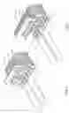
FIG. 3 is a schematic view for the radiator of the present invention.
FIG. 4 is a perspective view for the radiator of the present invention.
FIG. 5 is a side view for the radiator of the present invention.
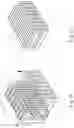
FIG. 6 is a perspective view for the example of the two-piece radiator of the present invention.
FIG. 7 is a schematic drawing illustrating the example for the two-piece radiator of the present invention.
FIG. 8 is a schematic drawing illustrating the second example for the radiator and the bottom plate.
FIG. 9 is a schematic drawing illustrating the second example for the radiator and the bottom plate.
FIG. 10 is a schematic drawing illustrating the third example for the reverse radiator.
FIG. 11 is a perspective view for the third example of the radiator.
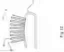
FIG. 12 is a side view for the fourth example of the radiator.
DETAILED DESCRIPTION OF THE INVENTION
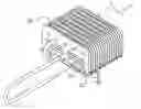
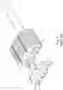
Referring to FIGS. 3 through 5, the improved structure of the LED radiator comprises a better heat-dissipating plate (2). A radiator (3) bended through machine has plurality of bottom area (21), side area (22), top area (23) and side area (22) which arranged continuously in upwardly opening order. The length of the top area (23) and the bottom area (21) on the radiator (3) is the same. The top area (23) and the bottom area (21) are respectively vertical with the side area (22), therefore, there is a space between top and the bottom as shown in FIGS. 4 and 5. The length of each side area (22) is the same and is longer than the length of the top area (23) and the bottom area (21).
As shown in FIGS. 6 and 7, the example of the present invention, the radiator (3) can be adhesive with the top radiator (40) and the bottom radiator (41) to form a two-piece radiator (4) which has the same size as the radiator (3) shown in FIG. 4.
As shown in FIGS. 8 and 9, the second example of the present invention, the radiator (5) comprises a bottom plate (52) and two-piece heat-dissipating chips (50) or plurality of heat-dissipating chips (51). After the two-piece heat-dissipating chips (50) and the plurality of heat-dissipating chips (51) are formed through the machine, the two-piece heat-dissipating chips (50) has a bottom area (21) and two side areas (22) vertical with the bottom area (21), and the plurality of heat-dissipating chips (51) has more than two bottom areas (21) and more than two side areas (22). A bottom plate (52) in proper size can be fixed with more two-piece heat-dissipating chips (50) or plurality of heat-dissipating chips (51) thereon to form a radiator (5).
As shown in FIGS. 8 and 9, more pairs of corresponding fastened members (53) are set upwardly on the surface of the bottom plate (52). When two-piece heat-dissipating chips (50) or plurality of heat-dissipating chips (51) are set on the bottom plate (52), the fastened members (53) can be bended on the bottom area (21) between two side areas (22) to fix the two-piece heat-dissipating chips (50) or plurality of heat-dissipating chips (51).
As shown in FIGS. 10 and 11 along with FIG. 4, the third example of the present invention, the radiator (3) can be designed as a long-shaped radiator (6). The way to produce the long-shaped radiator (6) and the radiator (3) is the same, but the shape and the size are different. Move the long-shaped radiator (6) shown in FIG. 10 clockwise or counterclockwise to an angle of ninety degree, we will see the long-shaped radiator (6) shown in FIG. 11 is the same as the radiator (3) shown in FIG. 4. The difference is where the bottom area (21) and the top area (23) are in lengthwise position and the side areas (22) are in sidelong position.
As shown in FIG. 12, the fourth example of the present invention, the bottom of the radiator (3) can be designed as an arc and can be fixed with the curved heat-dissipating pipe (7). Therefore, the side areas (22) will spread radially to larger the space of each side area (22) and to increase the heat dissipating effect.
The present invention mentioned above has the advantages as following:
-
- 1. The radiator (3) of the present invention uses a better heat-dissipating plate (2) bended through the machine as plurality of bottom area (21), side areas (22) and top area (23). The molded structure of the radiator (3) not only rids of the work done by hand but also allows for the speed of the production. It may lower the cost and increase the competitiveness.
- 2. The radiator (3) of the present invention is molded through the machine. It needs no design of the procedures for the circulation, thus it has economic efficiency.
- 3. The radiator (3) of the present invention is molded through the machine. It prevents the radiator (3) which dissipates the heat coming from the LED lights from melting the whole structure and keeps best heat dissipating effect.
Claims
I claim:1. An improved structure of LED radiator comprising:
a better heat-dissipating plate and;
a bottom area, side area, top area and side area which arranged continuously in upwardly opening order;
the space length of said top area and said bottom area on said radiator is the same;
said top area and said bottom area are respectively vertical with said side area, there is a space between each side area;
the length of each side area is the same and said side area is longer than the length of said top area and said bottom area.
2. An improved structure of LED radiator as recited in claim 1, wherein
said radiator can be adhesive with a top radiator and a bottom radiator to form a two-piece radiator.
3. An improved structure of LED radiator as recited in claim 1, wherein
said radiator comprises:
a bottom plate and two-piece heat-dissipating chips or plurality of heat-dissipating chips;
said two-piece heat-dissipating chips and said plurality of heat-dissipating chips are formed through the machine, said two-piece heat-dissipating chips have a bottom area and two side areas vertical with said bottom area;
said plurality of heat-dissipating chips have more than two bottom areas and more than two side areas;
a bottom plate in proper size can be fixed with more said two-piece heat-dissipating chips or said plurality of heat-dissipating chips thereon to form said radiator.
4. An improved structure of LED radiator as recited in claim 3 wherein
more pairs of corresponding fastened members are set upwardly on the surface of said bottom plate; when said two-piece heat-dissipating chips or said plurality of heat-dissipating chips are set on said bottom plate, said fastened members can be bended on said bottom area between two side areas to fix said two-piece heat-dissipating chips or said plurality of heat-dissipating chips.
5. An improved structure of LED radiator as recited in claim 1, wherein
said radiator can be designed as a long-shaped radiator;
the way to produce said long-shaped radiator and said radiator is the same, but the shape and the size are different;
move said long-shaped radiator clockwise or counterclockwise to an angle of ninety degree, said long-shaped radiator is the same as said radiator;
the difference is where said bottom area and said top area are at lengthwise position and said side areas are at the sidelong position.
6. An improved structure of LED radiator as recited in claim 1, wherein
the bottom of said radiator can be designed as an arc and can be fixed with a curved heat-dissipating pipe;
said side areas will spread radially to larger the space of each side area and to increase the heat dissipating effect.
Images & Drawings included:

Sources:
- United States Patent and Trademark Office - verify current appl. status at the USPTO↗
Similar patent applications:
- » 20150003082
LED LAMP RADIATING STRUCTURE - » 20130075780
RADIATION HEAT DISSIPATION LED STRUCTURE AND THE MANUFACTURING METHOD THEREOF - » 20120075860
LED lighting equipment with radiating structure having increased surface area and high ventilation efficiency - » 20090154173
LED lighting equipment and heat radiating structure - » 20100202144
Module structure of the LED lights and radiator - » 20170170360
LED structures for reduced non-radiative sidewall recombination - » 20180097145
LED structures for reduced non-radiative sidewall recombination - » 20190115495
LED structures for reduced non-radiative sidewall recombination - » 20190371964
LED structures for reduced non-radiative sidewall recombination - » 20130248584
Process for making a heat radiating structure for high-power LED
Recent applications in this class:
- » 20240183523 2024-06-06
ENHANCED THERMAL DESIGN FOR HIGH POWER LIGHTING FIXTURE - » 20240125464 2024-04-18
Heat Dissipation Arrangement for LED Lighting Fixtures - » 20230243496 2023-08-03
LED curing apparatus and cooling module - » 20230243495 2023-08-03
Outdoor LED illumination system with pole-mounted backplane - » 20230175683 2023-06-08
Film and television lamp - » 20230075501 2023-03-09
Heat dissipation device and lighting device - » 20220397265 2022-12-15
Composite fin heat sink - » 20220003401 2022-01-06
Method for remotely cooling a scope-mounted (distal) arthroscopic light source - » 20210348752 2021-11-11
Partially lighted T-bar - » 20210254821 2021-08-19
Rotating light emitting diode high mast luminaire