Object detection device
US20110010046A1
2011-01-13
12/831,473
2010-07-07
✅ Patent granted
US 9,626,868 B2
2017-04-18
-
-
Jeffrey Shapiro
Dinsmore & Shohl LLP
2032-06-19
Abstract:
An object detection device can acquire information of an object in the vicinity of a host-vehicle for appropriate traveling assistance. An object detection device 1 includes a vehicle state detection section 2, an environmental situation acquisition section 3, a road information acquisition section 4, a detection control section 6, and a detection section 7. A host-vehicle state prediction section 61 acquires a target state of a host-vehicle 81. The detection section 7 detects an object. A parameter setting section 63 switches the detection characteristic of the object in the detection section 7 in accordance with the target state.
Inventors:
- Toshiki Kindo 93 🇯🇵 Yokohama-shi, Japan
- Katsuhiro Sakai 28 🇯🇵 Hadano-shi, Japan
- Masahiro Harada 12 🇯🇵 Atsugi-shi, Japan
- Toshiki Kindo 103 🇯🇵 Yokohama, Japan
- Katsuhiro Sakai 37 🇯🇵 Hadano, Japan
- Masahiro Harada 15 🇯🇵 Atsugi, Japan
Assignee:
- TOYOTA JIDOSHA KABUSHIKI KAISHA 25,166 🇯🇵 Toyota-shi, Japan
Applicant:
Interested in similar patents?
Get notified when new applications in this technology area are published.
Classification:
G01S13/935 » CPC further
Systems using the reflection or reradiation of radio waves, e.g. radar systems; Analogous systems using reflection or reradiation of waves whose nature or wavelength is irrelevant or unspecified; Radar or analogous systems specially adapted for specific applications for anti-collision purposes of aircraft or spacecraft for terrain-avoidance
G06F7/00 IPC
Methods or arrangements for processing data by operating upon the order or content of the data handled
G08G1/166 » CPC main
Traffic control systems for road vehicles; Anti-collision systems for active traffic, e.g. moving vehicles, pedestrians, bikes
B60K31/0008 » CPC further
Vehicle fittings, acting on a single sub-unit only, for automatically controlling vehicle speed, i.e. preventing speed from exceeding an arbitrarily established velocity or maintaining speed at a particular velocity, as selected by the vehicle operator including means for detecting potential obstacles in vehicle path
B60L3/0007 » CPC further
Electric devices on electrically-propelled vehicles for safety purposes; Monitoring operating variables, e.g. speed, deceleration or energy consumption Measures or means for preventing or attenuating collisions
B60L3/0015 » CPC further
Electric devices on electrically-propelled vehicles for safety purposes; Monitoring operating variables, e.g. speed, deceleration or energy consumption; Measures or means for preventing or attenuating collisions Prevention of collisions
B60Q1/525 » CPC further
Arrangement of optical signalling or lighting devices, the mounting or supporting thereof or circuits therefor the devices being primarily intended to indicate the vehicle, or parts thereof, or to give signals, to other traffic for indicating other intentions or conditions, e.g. request for waiting or overtaking automatically indicating risk of collision between vehicles in traffic or with pedestrians, e.g. after risk assessment using the vehicle sensor data
B60Q5/006 » CPC further
Arrangement or adaptation of acoustic signal devices automatically actuated indicating risk of collision between vehicles or with pedestrians
B60Q9/004 » CPC further
Arrangement or adaptation of signal devices not provided for in one of main groups - , e.g. haptic signalling for parking purposes, e.g. for warning the driver that his vehicle has contacted or is about to contact an obstacle using wave sensors
B60Q9/006 » CPC further
Arrangement or adaptation of signal devices not provided for in one of main groups - , e.g. haptic signalling for parking purposes, e.g. for warning the driver that his vehicle has contacted or is about to contact an obstacle using wave sensors using a distance sensor
B60Q9/008 » CPC further
Arrangement or adaptation of signal devices not provided for in one of main groups - , e.g. haptic signalling for anti-collision purposes
B60R21/0134 » CPC further
Arrangements or fittings on vehicles for protecting or preventing injuries to occupants or pedestrians in case of accidents or other traffic risks; Electrical circuits for triggering safety arrangements, in case of vehicle accidents or impending vehicle accidents including means for detecting collisions, impending collisions or roll-over responsive to imminent contact with an obstacle, e.g. using radar systems
B60W30/08 » CPC further
Purposes of road vehicle drive control systems not related to the control of a particular sub-unit, e.g. of systems using conjoint control of vehicle sub-units, or advanced driver assistance systems for ensuring comfort, stability and safety or drive control systems for propelling or retarding the vehicle predicting or avoiding probable or impending collision
G01S13/93 » CPC further
Systems using the reflection or reradiation of radio waves, e.g. radar systems; Analogous systems using reflection or reradiation of waves whose nature or wavelength is irrelevant or unspecified; Radar or analogous systems specially adapted for specific applications for anti-collision purposes
B62D15/0265 » CPC further
Steering not otherwise provided for; Steering position indicators ; Steering position determination; Steering aids; Active steering aids, e.g. helping the driver by actively influencing the steering system after environment evaluation Automatic obstacle avoidance by steering
G01S15/93 » CPC further
Systems using the reflection or reradiation of acoustic waves, e.g. sonar systems; Sonar systems specially adapted for specific applications for anti-collision purposes
G08G3/02 » CPC further
Anti-collision systems
G05D1/0289 » CPC further
Control of position, course or altitude of land, water, air, or space vehicles, e.g. automatic pilot; Control of position or course in two dimensions specially adapted to land vehicles involving a plurality of land vehicles, e.g. fleet or convoy travelling with means for avoiding collisions between vehicles
B60R21/013 » CPC further
Arrangements or fittings on vehicles for protecting or preventing injuries to occupants or pedestrians in case of accidents or other traffic risks; Electrical circuits for triggering safety arrangements, in case of vehicle accidents or impending vehicle accidents including means for detecting collisions, impending collisions or roll-over
G08G5/04 » CPC further
Traffic control systems for aircraft, e.g. air-traffic control [ATC] Anti-collision systems
G08G7/02 » CPC further
Anti-collision systems
G08G5/045 » CPC further
Traffic control systems for aircraft, e.g. air-traffic control [ATC]; Anti-collision systems Navigation or guidance aids, e.g. determination of anti-collision manoeuvers
B60W30/16 » CPC further
Purposes of road vehicle drive control systems not related to the control of a particular sub-unit, e.g. of systems using conjoint control of vehicle sub-units, or advanced driver assistance systems for ensuring comfort, stability and safety or drive control systems for propelling or retarding the vehicle cruise control Adaptive Control of distance between vehicles, e.g. keeping a distance to preceding vehicle
B60T2201/022 » CPC further
Particular use of vehicle brake systems; Special systems using also the brakes; Special software modules within the brake system controller; Active or adaptive cruise control system; Distance control Collision avoidance systems
G05B2219/39082 » CPC further
Program-control systems; Nc systems; Robotics, robotics to robotics hand Collision, real time collision avoidance
G05B2219/39091 » CPC further
Program-control systems; Nc systems; Robotics, robotics to robotics hand Avoid collision with moving obstacles
G08G1/16 » CPC further
Traffic control systems for road vehicles Anti-collision systems
G05D1/02 IPC
Control of position, course or altitude of land, water, air, or space vehicles, e.g. automatic pilot Control of position or course in two dimensions
G06F17/10 IPC
Digital computing or data processing equipment or methods, specially adapted for specific functions Complex mathematical operations
G06G7/78 IPC
Devices in which the computing operation is performed by varying electric or magnetic quantities; Analogue computers for specific processes, systems or devices, e.g. simulators for direction-finding, locating, distance or velocity measuring, or navigation systems
B60Q1/52 IPC
Arrangement of optical signalling or lighting devices, the mounting or supporting thereof or circuits therefor the devices being primarily intended to indicate the vehicle, or parts thereof, or to give signals, to other traffic for indicating other intentions or conditions, e.g. request for waiting or overtaking for indicating emergencies
B60Q5/00 IPC
Arrangement or adaptation of acoustic signal devices
B60Q9/00 IPC
Arrangement or adaptation of signal devices not provided for in one of main groups - , e.g. haptic signalling
B60T8/1755 IPC
Arrangements for adjusting wheel-braking force to meet varying vehicular or ground-surface conditions, e.g. limiting or varying distribution of braking force; Using electrical or electronic regulation means to control braking Brake regulation specially adapted to control the stability of the vehicle, e.g. taking into account yaw rate or transverse acceleration in a curve
B62D15/02 IPC
Steering not otherwise provided for Steering position indicators ; Steering position determination; Steering aids
B60K31/00 IPC
Vehicle fittings, acting on a single sub-unit only, for automatically controlling vehicle speed, i.e. preventing speed from exceeding an arbitrarily established velocity or maintaining speed at a particular velocity, as selected by the vehicle operator
G06K9/00 IPC
Methods or arrangements for recognising patterns
B60R21/01 IPC
Arrangements or fittings on vehicles for protecting or preventing injuries to occupants or pedestrians in case of accidents or other traffic risks Electrical circuits for triggering safety arrangements, in case of vehicle accidents or impending vehicle accidents
B60L3/00 IPC
Electric devices on electrically-propelled vehicles for safety purposes; Monitoring operating variables, e.g. speed, deceleration or energy consumption
B60W30/095 » CPC further
Purposes of road vehicle drive control systems not related to the control of a particular sub-unit, e.g. of systems using conjoint control of vehicle sub-units, or advanced driver assistance systems for ensuring comfort, stability and safety or drive control systems for propelling or retarding the vehicle predicting or avoiding probable or impending collision Predicting travel path or likelihood of collision
B60T8/17558 » CPC further
Arrangements for adjusting wheel-braking force to meet varying vehicular or ground-surface conditions, e.g. limiting or varying distribution of braking force; Using electrical or electronic regulation means to control braking; Brake regulation specially adapted to control the stability of the vehicle, e.g. taking into account yaw rate or transverse acceleration in a curve specially adapted for collision avoidance or collision mitigation
B60R2021/01013 » CPC further
Arrangements or fittings on vehicles for protecting or preventing injuries to occupants or pedestrians in case of accidents or other traffic risks; Electrical circuits for triggering safety arrangements, in case of vehicle accidents or impending vehicle accidents Means for detecting collision, impending collision or roll-over
B60R2300/8093 » CPC further
Details of viewing arrangements using cameras and displays, specially adapted for use in a vehicle characterised by the intended use of the viewing arrangement for obstacle warning
Description
CROSS-REFERENCE TO RELATED APPLICATIONS
This Application claims priority of Japanese Patent Application No. 2009-164009 filed on Jul. 10, 2009, which is incorporated herein by reference.
BACKGROUND OF THE INVENTION
1. Field of the Invention
The present invention relates to an object detection device that detects an object by using data acquired from a sensing device or the like.
2. Related Background Art
In recent years, various systems have been provided which have an object detection device which is mounted in a vehicle to detect an object by using data acquired from a sensing device, such as a camera or a radar, and assist traveling of a driver on the basis of information from the object detection device. With regard to such an object detection device, various techniques for detecting an object with high accuracy have been suggested.
For example, Patent Document 1 (JP2007-329762A) describes an object detection device which predicts a region where there may be an object that should be detected from an image pattern of an in-vehicle camera, and attempts to detect the predicted region intensively, thereby improving object acquisition accuracy. In the object detection device of Patent Document 1, object detection accuracy is adjusted in accordance with the image pattern so as to reduce the processing load of the system.
SUMMARY OF THE INVENTION
However, in the object detection device of the related art, the detection accuracy can be adjusted in accordance with the position of the host-vehicle by using data acquired from the image pattern, but adjustment may not be provided in consideration of the behavior of the host-vehicle, that is, the predicted route of the host-vehicle. For this reason, it may be impossible to acquire necessary information for appropriate traveling assistance of the host-vehicle.
An object of the invention is to provide an object detection device capable of acquiring information of an object in the vicinity of a host-vehicle for appropriate traveling assistance.
An aspect of the invention provides an object detection device which is mounted in a vehicle and detects an object in the vicinity of the host-vehicle. The object detection device includes a host-vehicle state prediction unit that acquires a target state of the host-vehicle, a detection unit that detects the object, and a detection characteristic control unit that switches the detection characteristic of the object in the detection unit in accordance with the target state.
Here, the detection characteristic of the object refers to the performance of the detection unit which is determined by a detection rate and an erroneous detection rate. With regard to switching of the detection characteristic of the object according to the target state, the parameters and the like in the single detection unit may be changed in accordance with the target state, or a plurality of detection units having different detection characteristics may be switched in accordance with the target state. The target state of the host-vehicle refers to the position, the target route, or the like of the host-vehicle after a predetermined time.
According to this object detection device, in a situation where there are a plurality of choices regarding the target state of the host-vehicle, the detection characteristic of the object is switched in accordance with the target state of the host-vehicle. Thus, the detection characteristic of the object is switched in accordance with when the host-vehicle travels in a straight line, turns left, turns right, or the like. As a result, information according to the target state of the host-vehicle is acquired, such that it is possible to acquire information of the object in the vicinity of the host-vehicle necessary for appropriate traveling assistance.
The object detection device according to the aspect of the invention may further include a road information acquisition unit which acquires information regarding a road, and a determination unit which determines a possible collision form in the host-vehicle on the basis of the information regarding the road and the target state. The detection characteristic control unit may switch the detection characteristic in accordance with the collision form. The term “information regarding the road” used herein includes position information of a road structure, such as lanes and intersections, and information regarding traffic rules, such as regulations in terms of road structures and traveling priority. Thus, for example, the information that “part of the target route of the host-vehicle is deviated from the traffic rules” can be acquired, and in such a state, it can be determined that the host-vehicle may collide against another vehicle. As a result, it is possible to acquire information of the object in the vicinity of the host-vehicle necessary for preventing the host-vehicle from colliding against another vehicle in a state where the host-vehicle interferes with the route of another vehicle.
In the object detection device according to the aspect of the invention, the detection characteristic control unit may switch the detection characteristic by adjusting a detection rate. That is, the detection characteristic of the detection unit can be set on the basis of an ROC curve which represents the relationship between the detection rate and an erroneous detection rate. In this case, one detection rate is adjusted to switch the detection characteristic. Thus, for example, even when the erroneous detection rate increases, the detection rate increases, or the detection rate decreases to decrease the erroneous detection rate, such that it is possible to switch the detection characteristic of the detection unit in accordance with the behavior of the host-vehicle, that is, the predicted route of the host-vehicle.
In the object detection device according to the aspect of the invention, when a collision form is determined where the host-vehicle interferes with the route of another vehicle, the detection characteristic control unit may switch the detection characteristic such that the detection rate in the detection unit increases. Thus, when the host-vehicle interferes with the route of another vehicle, for example, when the host-vehicle strays to the opposing lane when turning right at the intersection, giving top priority to keeping an eye on another vehicle such that the host-vehicle does not collide against another vehicle which is traveling on the opposing lane, the detection unit can be switched such that the non-detection rate is lower than the erroneous detection rate.
According to the aspect of the invention, it is possible to acquire information of an object in the vicinity of a host-vehicle necessary for appropriate traveling assistance.
BRIEF DESCRIPTION OF THE DRAWINGS
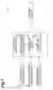
FIG. 1 is a block diagram showing the functional configuration of an object detection device according to an embodiment of the invention.
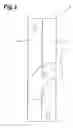
FIG. 2 is a diagram showing an example of road information which is acquired by a road information acquisition section of FIG. 1.
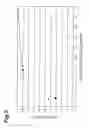
FIG. 3 is a diagram illustrating parameters which are set by a parameter setting section of FIG. 1.
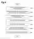
FIG. 4 is a flowchart showing an operation in the object detection device of FIG. 1.
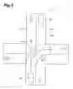
FIG. 5 is a diagram showing road information which is acquired by a road information acquisition section of FIG. 1 and a route which is predicted by a host-vehicle state prediction section.
FIG. 6 is a diagram illustrating an ROC curve of a detection section according to another embodiment of the invention.
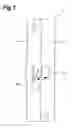
FIG. 7 is a diagram illustrating a probability that a host-vehicle will interfere with the route of another vehicle.
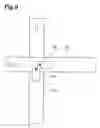
FIG. 8 is a diagram illustrating a probability that a host-vehicle will interfere with the route of another vehicle.
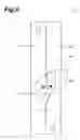
FIG. 9 is a diagram illustrating a probability that a host-vehicle will interfere with the route of another vehicle.
FIG. 10 is a diagram illustrating a probability that a host-vehicle will interfere with the route of another vehicle.
DETAILED DESCRIPTION OF THE PREFERRED EMBODIMENTS
Hereinafter, an object detection device 1 according to another embodiment will be described with reference to FIGS. 1 to 5. In the description of the drawings, the same parts are represented by the same reference numerals, and overlapping description will be omitted. FIG. 1 is a block diagram showing the functional configuration of the object detection device 1 according to the embodiment of the invention.
As shown in FIG. 1, the object detection device 1 includes a vehicle state detection section 2, an environmental situation acquisition section 3, a road information acquisition section (road information acquisition unit) 4, a detection control section 6, and a detection section (detection unit) 7.
The vehicle state detection section 2 functions as a vehicle state detection unit which detects position information of a vehicle, vehicle speed information, and the like. For the vehicle state detection section 2, for example, a GPS (Global Positioning System), a wheel speed sensor, and the like are used. The GPS acquires position information of the vehicle. The wheel speed sensor is attached to, for example, the wheels of the vehicle, and acquires the wheel speed of the vehicle. The vehicle state detection section 2 is connected to the detection control section 6, and outputs acquired vehicle state information, such as position information and wheel speed information, to the detection control section 6.
The environmental situation acquisition section 3 functions as an environmental situation acquisition unit which acquires environmental situation information in the vicinity of the host-vehicle 81. For the environmental situation acquisition section 3, for example, an vehicle-to-vehicle communication device, a road-to-vehicle communication device, or a radar sensor using millimeter waves or laser is used. When a vehicle-to-vehicle communication device or a road-to-vehicle communication device is used, position information and vehicle speed information of another vehicle 82 can be acquired. When a millimeter-wave radar sensor or the like is used, position information and relative speed information of another vehicle 82 and an obstacle on the route can be acquired. The environmental situation acquisition section 3 is connected to the detection control section 6, and outputs acquired environmental situation information in the vicinity of the host-vehicle 81 to the detection control section 6.
The road information acquisition section 4 acquires road information (information regarding the road) including position information of road structures, such as lanes and intersections, and traffic rules, such as regulations in terms of road structures, traveling priority, and conventional etiquette. The road information acquisition section 4 may acquire road information from a road database stored in a storage section (not shown) mounted in the host-vehicle, or may acquire road information from a database stored in an external server through a communication device. A determination section (determination unit) 62 which will be described below acquire road information to obtain information such as “the position of the host-vehicle is deviated from the traffic rules”, for example.
An example of the road database will be described with reference to FIG. 2. FIG. 2 shows an example where the contents of a road database are schematically visualized. The road database outputs traffic rules corresponding to the designated position and time in response to a request from the determination section 62 which will be described below. The contents of the map database are constituted by region information (when a region is represented by a rectangle, the position (X,Y) of each apex), to which the same traffic rule is applied, and the relevant traffic rule. The traffic rule includes the traveling direction of the relevant region, the speed limit, possibility of stopping, presence/absence of a crosswalk, presence/absence of a stop line, and the like. A road shown in FIG. 2 will be described. A road A is defined by three regions {A1, A2, A3}. Then, for example, the region A1 is defined by the traffic rules such that the speed limit is 50 km/h, the traveling direction is the direction indicated by a white arrow in the drawing, stopping is inhibited, there is no crosswalk, and there is no stop line. The map database defines the possibility of transition between the regions A1, A2, and A3. For example, as shown in FIG. 2, it is defined such that transition from the region A1 to the region A2 is inhibited, and transition from the region A2 to the region A1 and from the region A1 to the region A3 is permitted.
The detection control section 6 controls the detection section 7 which will be described below. For example, the detection control section 6 primarily includes a computer having a CPU, a ROM, and a RAM (not shown). The detection control section 6 is connected to the vehicle state detection section 2, the environmental situation acquisition section 3, the road information acquisition section 4, and the detection section 7. The detection control section 6 receives various kinds of information from the vehicle state detection section 2, the environmental situation acquisition section 3, the road information acquisition section 4, and outputs various kinds of information to the detection section 7. The detection control section 6 has a host-vehicle state prediction section (host-vehicle state prediction unit) 61, a determination section 62, and a parameter setting section (detection characteristic control unit) 63.
The host-vehicle state prediction section 61 acquires a target state of the host-vehicle 81. Specifically, the host-vehicle state prediction section 61 predicts the state of the host-vehicle 81 after a predetermined time from position information of the vehicle, vehicle speed information, and the like acquired by the vehicle state detection section 2. The host-vehicle state prediction section 61 exhaustively predicts the position of the host-vehicle 81, and in this case, any methods may be used. The target state of the host-vehicle 81 is preferably acquired as a target route. The term “target route” used herein refers to a concept including temporal elements, such as time, speed, and the like, and is different from the term “route” which does not include the concept of such temporal elements.
The determination section 62 determines a possible collision form in the host-vehicle 81 on the basis of information regarding the road acquired by the road information acquisition section 4 and the target state acquired by the host-vehicle state prediction section 61. Specifically, the determination section 62 determines whether or not the target route predicted by the host-vehicle state prediction section 61 is likely to interfere with the route of another vehicle 82. The determination of whether or not the host-vehicle 81 interferes with the route of another vehicle 82 may be made on the basis of the traffic rule acquired by the road information acquisition section 4.
The parameter setting section 63 switches the detection characteristic of the object in the detection section 7 described below in accordance with the possible collision form acquired by the determination section 62. That is, the detection characteristic, such as the detection rate of the detection section 7, is switched. The detection characteristic of the detection section 7 is determined by an ROC curve which represents the relationship between a detection rate and an erroneous detection rate. In this case, if the detection rate increases, the erroneous detection rate increases, and if the detection rate decreases, the erroneous detection rate decreases. With regard to processing of data (raw data) in the detection section 7, when a template is used, the number of templates increases or decreases, or when a hierarchical template structure is used, a hierarchy to be used changes or the processing cycle changes. Specifically, the parameter setting section 63 adjusts a parameter in an ROC curve which represents the detection characteristic of the object (a curve which represents the relationship between a detection rate and an erroneous detection rate).
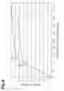
As shown in FIG. 3, the ROC curve is a graph which has the vertical axis representing a detection rate and the horizontal axis representing the erroneous detection rate. The detection characteristic (performance) of all object detectors or discriminators necessary for object extraction can be implemented on the graph. That is, the detection characteristic of the detection section 7 is realized by a single line shown in FIG. 3. When parameters are set to determine an arbitrary point on the line, the detection section 7 can exhibit the performance at the relevant point. For example, a point a shown in FIG. 3 shows a detection characteristic that the detection rate is relatively low (about 0.3) and the erroneous detection rate is also relatively low (about 0.1). Meanwhile, a point b shows a detection characteristic that the detection rate is relatively high (about 0.9) and the erroneous detection rate is also relatively high (about 0.4). When the parameters are set by the parameter setting section 63, the detection section 7 can exhibit the detection characteristic at the point a and the detection characteristic at the point b.
In this embodiment, the difference between the detection characteristics at the points a and b is used. That is, when the host-vehicle 81 is likely to interfere with the route of another vehicle 82, the parameter setting section 63 sets parameters such that the detection characteristic at the point b can be exhibited. When the host-vehicle 81 is unlikely to interfere with the route of another vehicle 82, the parameter setting section 63 sets the parameters such that the detection characteristic at the point a can be exhibited. Thus, when the host-vehicle 81 is likely to interfere with the route of another vehicle 82, even if the erroneous detection rate is high, elimination of detection leakage (non-detection) is directed such that collision can be reliably prevented. Meanwhile, when the host-vehicle 81 is unlikely to interfere with the route of another vehicle 82, even if the detection rate is low, prevention of sudden braking or the like is directed such that an adverse effect on the ride quality can be avoided as much as possible.
The host-vehicle state prediction section 61, the determination section 62, and the parameter setting section 63, which are shown in FIG. 1 and provided in the detection control section 6, may be constituted by loading a program on the computer or may be constituted by individual hardware.
The detection section 7 switches the detection characteristic of the object in accordance with the target state of the host-vehicle 81 to detect the object. For example, a sensing device, such as a camera or a radar, or the like corresponds to the detection section 7. As described above, when the parameters are set by the parameter setting section 63, the detection section 7 switches the detection characteristic of the object.
Next, the operation of the object detection device 1 will be described with reference to FIG. 4. FIG. 4 is a flowchart showing a flow of characteristic processing which is executed by the object detection device 1.
First, the vehicle state detection section 2 acquires the state (position, speed, and the like) of the host-vehicle 81 (S01). Then, the vehicle state detection section 2 outputs acquired information to the detection control section 6.
Next, the environmental situation acquisition section 3 acquires the position and state of another object in the vicinity of the host-vehicle 81 (S02), and outputs acquired information to the detection control section 6. Hereinafter, it is assumed that the position of another object is the value of the center of another object, and the state of another object is specified by the position, speed, and the like.
Next, the host-vehicle state prediction section 61 predicts the target state of the host-vehicle 81, such as the future position, speed, direction, and the like, from information regarding the state of the host-vehicle 81, such as the position, speed, direction, and the like, input from the vehicle state detection section 2 (S03). Here, the target state is preferably, for example, target routes w1 and w2 shown in FIG. 5. The target routes w1 and w2 define the time until the host-vehicle 81 reaches each location or a destination, as well as the coordinates (x,y) of a target position.
Returning to FIG. 4, next, the determination section 62 acquires road information including the traffic rules and the like from the road information acquisition section 4 (S04). For example, as shown in FIG. 5, the determination section 62 acquires position information of the regions A1, A2, and A3 of the traveling road, and the priority at the time of traveling in the regions A1, A2, and A3. Here, the following description will be provided assuming that information that “the priority at the time of traveling in the region A2 is higher than the priority at the time of traveling in the region A3” can be acquired.
Next, the determination section 62 determines whether the host-vehicle 81 is likely to interfere with the route of another vehicle 82 or not on the basis of the road information acquired in Step S04 and the target routes w1 and w2 acquired by the host-vehicle state prediction section 61 (S05). When the determination section 62 determines whether or not the host-vehicle 81 is likely to interfere with the route of another vehicle 82, for example, the priorities of the regions A1, A2, and A3 acquired in Step S04 may be used. For example, as shown in FIG. 5, when the host-vehicle 81 collides against another vehicle 82, which is traveling in the region A2, while traveling in the region A3, the target route w1 is determined as a route where the host-vehicle 81 is likely to interfere with the route of another vehicle 82.
Returning to FIG. 4, next, the parameter setting section 63 calculates parameters, which should be set in the detection section 7, in accordance with the collision form acquired in Step S05 (S06). Here, since the target route w1 is determined as a route where the host-vehicle 81 is likely to interfere with the route of another vehicle 82, the parameter setting section 63 calculates parameters which realizes a detection characteristic such that a permissible non-detection rate, that is, an erroneous detection rate increases to eliminate non-detection. Meanwhile, since the target route w2 is determined as a route where the host-vehicle 81 is unlikely to interfere with the route of another vehicle 82, the parameter setting section 63 calculates parameters which realize a detection characteristic such that, even when the detection rate decreases, erroneous detection is eliminated.
Next, the parameter setting section 63 sets the parameters calculated in Step S06 in the detection section 7 (S07). Thus, the detection section 7 can reliably detect another vehicle 82 which is located in the region A2, such that the host-vehicle 81 can be prevented from colliding against another vehicle 82.
As described above, according to the object detection device 1 of this embodiment, as shown in FIG. 5, in the situation where there are a plurality of choices of the target routes w1 and w2 of the host-vehicle 81, the parameters are set which switch the detection characteristic of the detection section 7 in accordance with the target state of the host-vehicle 81. That is, for traveling in a straight line and making a right turn at an intersection shown in FIG. 5, the parameters are set which switch the detection characteristic of the detection section 7. Thus, when the host-vehicle 81 is likely to interfere with the route of another vehicle 82, even when the erroneous detection rate increases, the elimination of detection leakage (non-detection) is directed such that collision can be reliably prevented. Meanwhile, when the host-vehicle 81 is unlikely to interfere with the route of another vehicle 82, even when the detection rate decreases, the prevention of sudden braking or the like due to erroneous detection is directed such that the adverse effect on the ride quality can be avoided as much as possible. As a result, information according to the target state of the host-vehicle 81 is acquired, such that it is possible to acquire information of the object in the vicinity of the host-vehicle 81 necessary for appropriate traveling assistance.
Although the embodiment of the invention has been described, the invention is not limited to the embodiment, and various modifications may be made without departing from the scope and spirit of the invention.
Although, in the foregoing embodiment, an example has been described where the parameters are set by the parameter setting section 63, such that the detection characteristic of the detection section 7 is switched, the invention is not limited to this example.
For example, the parameter setting section 63 may switch ROC curves R1 and R2 shown in FIG. 6 to switch the detection characteristic of the detection section 7. In addition, for example, a plurality of detection sections having different ROC curves (detection characteristics) may be provided. In all of the cases, the detection characteristic of the detection section 7 can be switched in accordance with the target state of the host-vehicle 81.
In the object detection device 1 of the foregoing embodiment, an example has been described where it is determined whether or not the host-vehicle 81 is likely to interfere with the route of another vehicle 82 or not on the basis of the region at which the host-vehicle 81 is located. However, the invention is not limited to this example.
For example, as shown in FIG. 7, it may be determined whether the host-vehicle 81 is likely to interfere with the route of another vehicle 82 or not on the basis of an angle α between the direction of the host-vehicle 81 and the traveling direction of the region A1 where the host-vehicle 81 is located. For example, when the angle α between the direction of the host-vehicle 81 and the traveling direction of the region where the host-vehicle 81 is present is equal to or greater than a predetermined angle (for example, 45°), it may be determined that the host-vehicle 81 interferes with the route of another vehicle 82.
For example, as shown in FIG. 8, it may be determined whether the host-vehicle 81 is likely to interfere with the route of another vehicle 82 or not on the basis of the priority of the region A3 where the host-vehicle 81 is located and the priority of the region A2 where another vehicle 82 is located. For example, when the region A3 where the host-vehicle 81 is located has the priority lower than the region A2 where another vehicle 82 is located, it may be determined that the host-vehicle 81 interferes with the route of another vehicle 82. In comparison of the priorities of the region A3 where the host-vehicle 81 is located and the priority of the region A2 where another vehicle 82 is located, at an intersection shown in FIG. 9, it may be determined whether or not the host-vehicle 81 is likely to interfere with the route of another vehicle 82. The priority based on signal information as well as the priority based on the region where the host-vehicle 81 is located may be used. For example, a vehicle which runs into a green light has high priority, and a vehicle which runs into a red light has low priority.
For example, as shown in FIG. 10, it may be determined whether the host-vehicle 81 is likely to interfere with the route of another vehicle 82 or not on the basis of road markings 91 and 92. When the road marking 91 is a white line and the road marking 92 is a yellow line, if the host-vehicle 81 which is traveling in a region A1 changes lane to a region A2, the host-vehicle 81 violates the traffic rule. With regard to such traveling which violates the traffic rule, it may be determined that the host-vehicle 81 interferes with the route of another vehicle 82. For the determination of violations against the traffic rule, road signs as well as road markings may be used.
The determination of interference with the route of another vehicle 82 may be made on the basis of the fault proportion of automobile insurance, the judicial precedents, the vehicle performance, and the like.
The determination of the collision form may be made for collision against a pedestrian or a two-wheeled vehicle, such as a bicycle. In this case, host-vehicle surroundings information including a pedestrian or a bicycle in the vicinity of the host-vehicle is acquired, and it is determined whether or not the route of the host-vehicle is likely to interfere with the pedestrian or the bicycle in the vehicle surroundings information. Then, when it is determined that the route of the host-vehicle is likely to interfere with a pedestrian or a bicycle, since collision of the host-vehicle and the pedestrian or the bicycle is likely to cause extensive damage, a detection characteristic is preferably exhibited such that the erroneous detection rate increases, and the non-detection rate decreases to eliminate non-detection.
Claims
1. An object detection device which is mounted in a vehicle and detects an object in the vicinity of the host-vehicle, the object detection device comprising:
a host-vehicle state prediction unit that acquires a target state of the host-vehicle;
a detection unit that detects the object; and
a detection characteristic control unit that switches the detection characteristic of the object in the detection unit in accordance with the target state.
2. The object detection device according to claim 1, further comprising:
a road information acquisition unit that acquires information regarding a road; and
a determination unit that determines a possible collision form in the host-vehicle on the basis of the information regarding the road and the target state,
wherein the detection characteristic control unit switches the detection characteristic in accordance with the collision form.
3. The object detection device according to claim 1,
wherein the detection characteristic control unit switches the detection characteristic by adjusting a detection rate.
4. The object detection device according to claim 2,
wherein the detection characteristic control unit switches the detection characteristic by adjusting a detection rate.
5. The object detection device according to claim 3,
wherein, when a collision form is determined where the host-vehicle interferes with the route of another vehicle, the detection characteristic control unit switches the detection characteristic such that the detection rate in the detection unit increases.
6. The object detection device according to claim 4,
wherein, when a collision form is determined where the host-vehicle interferes with the route of another vehicle, the detection characteristic control unit switches the detection characteristic such that the detection rate in the detection unit increases.
Images & Drawings included:

Sources:
- United States Patent and Trademark Office - verify current appl. status at the USPTO↗
Similar patent applications:
- » 20220327844
Road surface detection device, object detection device, object detection system, mobile object, and object detection method - » 20210096247
Control device for object detection device, object detection device, and non-transitory computer-readable storage medium - » 20170356985
Circuit device, object detecting device, sensing device, mobile object device and object detecting device - » 20220317295
Object detection device, vehicle, method of setting wave receiving period in object detection device, and method of setting detection sensitivity in object detection device - » 20220113391
Object detection device, object detection method, and control device - » 20200182993
Object detection device, object detection method, and sensor device - » 20110164149
Object detection device, object detection system, integrated circuit for object detection, and object detection method - » 20090066513
Object detecting device, object detecting method and object detecting computer program - » 20140285372
Object detecting device, object detecting method, object detecting program, and motion control system - » 10486677
Object detection device, object detection server, and object detection method
Recent applications in this class:
- » 20250292685 2025-09-18
CONTROL APPARATUS, CONTROL METHOD THEREOF, AND STORAGE MEDIUM - » 20250285542 2025-09-11
DRIVING ASSISTANCE DEVICE, DRIVING ASSISTANCE METHOD, AND STORAGE MEDIUM STORING COMPUTER PROGRAM - » 20250285541 2025-09-11
DISPLAY CONTROL DEVICE, DISPLAY CONTROL METHOD, AND STORAGE MEDIUM - » 20250273072 2025-08-28
SYSTEM AND METHOD FOR MITIGATING VEHICLE COLLISION WITH A BICYCLE - » 20250265931 2025-08-21
ROADSIDE DEVICE - » 20250259545 2025-08-14
DRIVING ASSISTANCE DEVICE, DRIVING ASSISTANCE METHOD, AND STORAGE MEDIUM - » 20250239163 2025-07-24
VEHICLE WARNING SYSTEM AND WARNING METHOD - » 20250239162 2025-07-24
MONITORING DEVICE - » 20250232676 2025-07-17
FOLLOWING VEHICLE APPROACH NOTIFICATION DEVICE - » 20250232675 2025-07-17
INFORMATION-PROCESSING DEVICE, TERMINAL, INFORMATION-PROCESSING METHOD, ALARM METHOD, AND ALARM SYSTEM
Recent applications for this Assignee:
- » 20250294012 2025-09-18
GATEWAY DEVICE - » 20250293858 2025-09-18
SYSTEMS AND METHODS FOR SECURELY MANAGING ACCESS TO VEHICLE DATA - » 20250293569 2025-09-18
COOLING STRUCTURE - » 20250293539 2025-09-18
REDUNDANT POWER SUPPLY SYSTEM - » 20250293469 2025-09-18
CONNECTOR MOUNTING STRUCTURE - » 20250293409 2025-09-18
ELECTRICITY STORAGE CELL - » 20250293401 2025-09-18
CELL STACK - » 20250293400 2025-09-18
STORAGE CELL - » 20250293399 2025-09-18
POWER STORAGE CELL AND METHOD FOR MANUFACTURING THE SAME - » 20250293381 2025-09-18
POWER STORAGE DEVICE AND VEHICLE