Lathe with two workpiece spindles
US20120048075A1
2012-03-01
12/945,542
2010-11-12
✅ Patent granted
US 8,448,550 B2
2013-05-28
-
-
Daniel Howell | Ryan Rufo
Andrew Wilford
2031-12-03
Abstract:
A machining apparatus has a frame and two generally parallel horizontal guides on the frame, one of which extends through at least one loading station and through at least one work station. A slide carrying a pair of spindles each capable of gripping a workpiece is shiftable between positions with the spindles aligned with the stations. A tool holder is shiftable on the other of the guides toward and away from the work station. Respective guides between each of the spindles and the slide allow vertical movement of the spindles on the slide. Actuators shift the slide horizontally on the one guide, shift the tool holder horizontally parallel to the slide on the other guide, and shift the spindles vertically on the slide.
Inventors:
- Markus HESSBRUEGGEN 3 🇩🇪 Goeppingen, Germany
- Juergen Mueller 1 🇩🇪 Albershausen, Germany
- Juergen Moebus 1 🇩🇪 Donzdorf, Germany
Assignee:
- EMAG HOLDING GMBH 33 🇩🇪 Salach, Germany
Applicant:
Interested in similar patents?
Get notified when new applications in this technology area are published.
Classification:
B23Q39/028 » CPC further
Metal-working machines incorporating a plurality of sub-assemblies, each capable of performing a metal-working operation the sub-assemblies being capable of being brought to act at a single operating station with a plurality of workholder per toolhead in operating position
Y10T82/2508 » CPC further
Turning; Lathe with tool turret
Y10T82/2511 » CPC further
Turning; Lathe Vertical
Y10T82/2514 » CPC further
Turning; Lathe with work feeder or remover
Y10T82/2516 » CPC further
Turning; Lathe with work feeder or remover Magazine type
Y10T82/2524 » CPC further
Turning; Lathe Multiple
Y10T82/2552 » CPC further
Turning; Lathe Headstock
B23B3/30 » CPC further
General-purpose turning-machines or devices, e.g. centre lathes with feed rod and lead screw; Sets of turning-machines Turning-machines with two or more working-spindles, e.g. in fixed arrangement
B23B29/24 » CPC main
Holders for non-rotary cutting tools ; Boring bars or boring heads; Accessories for tool holders Tool holders for a plurality of cutting tools, e.g. turrets
Description
FIELD OF THE INVENTION
The present invention relates to a turning machine. More particularly this invention concerns a lathe with two workpiece spindles.
BACKGROUND OF THE INVENTION
As described in EP 1,171,309 a two-spindle lathe is moved along four axes so as to reduce the cycling time for machining workpieces. The control along the four axes is done by a complex digital control system, so the machine is expensive to manufacture, program, and maintain.
OBJECTS OF THE INVENTION
It is therefore an object of the present invention to provide an improved lathe with two workpiece spindles.
Another object is the provision of such an improved lathe with two workpiece spindles that overcomes the above-given disadvantages, in particular that is simpler than the prior-art such machine.
SUMMARY OF THE INVENTION
A machining apparatus has according to the invention a frame and two generally parallel horizontal guides on the frame, one of which extends through at least one loading station and through at least one work station offset horizontally from the loading station. A slide carrying a pair of spindles each capable of gripping a workpiece is shiftable between positions with the spindles aligned with the stations. A tool holder is shiftable on the other of the guides toward and away from the work station so that when one of the spindles is holding a workpiece in the work station and is rotating the workpiece the tool can machine the workpiece in the work station. Respective guides between each of the spindles and the slide allow vertical movement of the spindles on the slide. Actuators shift the slide horizontally on the one guide, shift the tool holder horizontally parallel to the slide on the other guide, and shift the spindles vertically on the slide.
A second such loading station symmetrically flanks the work station with the first-mentioned loading station. The loading stations are at the same spacing from a vertical center axis of the work station.
The spindles are driven to rotate a workpiece the hold about the axis when in the work station. Abutments on the frame define end positions for the slide in each of which one of the spindles is centered in a respective one of the loading stations.
Fresh workpieces are supplied to and finished workpieces are removed from each of the loading stations.
The tool holder holds a plurality of tools in a carousel rotatable about a horizontal axis parallel to the direction of displacement of the slide and tool holder.
BRIEF DESCRIPTION OF THE DRAWING
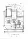
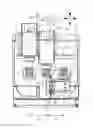
The above and other objects, features, and advantages will become more readily apparent from the following description, reference being made to the accompanying drawing whose sole figure is a schematic side view of the machine according to the invention.
SPECIFIC DESCRIPTION
As seen in the drawing, the machining apparatus according to the invention has a stationary frame 1. Driven workpiece spindle assemblies 3 and 3′ are mounted on a slide 4 movable along guides 9 fixed on the frame 1 in a horizontal direction X here parallel to the view plane. The spindles 3 and 3′ carry on their lower ends respective chuck 8 and 8′ for gripping and holding workpieces 7. The spindle 3 is in a work station 5. Directly next to it is a tool-holding carousel 2 riding on guides 11 on the frame 1 for movement also in the direction X. Since both the slide 4 and carousel 2 move in the same direction x, they take up only a small amount of space and are both quite accessible. One illustrated tool 13 is a chisel. In addition to fixed tools, driven tools can be used for milling, drilling, or grinding.
The spindles 3 and 3′ can also move relative to the slide 4 on respective vertical guides 10 and 10′ in a vertical direction Z also in the plane of the view. Two loading positions 6 and 6′ symmetrically and diametrally flank a vertical axis W of the work station 5 by a spacing A. A fixed horizontal spacing B between the two spindles 3 and 3′ is the same as the spacing A so the spindles 3 and 3′ are either in the work station 5 or one of the loading stations 6 and 6′
Thus according to the invention while one of the tools 13 is machining a workpiece 7 being rotated by one of the spindles 3 or 3′ in the station 5 about the axis W, another workpiece 7 can be unloaded from or loaded into the other of the spindles 3 and 3′ in the other station 6. The workpieces are transported into and out of the stations 6 and 6′ of the machine in a direction perpendicular to the plane of the view by standard conveyors 14 and 14′ according to the pickup principle. The result is a very short cycling time between machining operations.
End positions of the slide 4 with the spindles 3 and 3′ in the stations 6 and 6′ are defined by respective stops or abutments 12 and 12′ fixed on the frame 1 and engageable with the slide 4. Thus a simple actuator such as a hydraulic cylinder 15 can simply shift the slide 4 back and forth between the end positions defined by the stops 12 and 12′ so that fine digital control of the actuator 15 is not needed.
As the workpiece 7 is being machined in the work station 5, the tool can be shifted in the direction x by another actuator 16 like the actuator 15. Another such actuator 17 (only one shown) can shift each of the spindle drives 3 and 3′ along the respective guides 10 and 10′ vertically on the slide 4 so that the tool 13 can do its work.
Claims
We claim:1. A machining apparatus comprising:
a frame;
two generally parallel horizontal guides on the frame one of which extends through at least one loading station and through at least one work station offset horizontally from the loading station;
a slide carrying a pair of spindles each capable of gripping a workpiece, the slide shiftable between positions with the spindles aligned with the stations;
a tool holder shiftable on the other of the guides toward and away from the work station, whereby when one of the spindles is holding a workpiece in the work station and is rotating the workpiece, the tool can machine the workpiece in the work station; and
respective guides between each of the spindles and the slide for vertical movement of the spindles on the slide;
actuator means for shifting the slide horizontally on the one guide, for shifting the tool holder horizontally parallel to the slide on the other guide, and for shifting the spindles vertically on the slide.
2. The machining apparatus defined in claim 1 wherein a second such loading station symmetrically flanks the work station with the first-mentioned loading station, the loading stations being at the same spacing from a vertical center axis of the work station.
3. The machining apparatus defined in claim 2 wherein the spindles are driven to rotate a workpiece the hold about the axis when in the work station.
4. The machining apparatus defined in claim 2, further comprising
abutments on the frame defining end positions for the slide in each of which one of the spindles is centered in a respective one of the loading stations.
5. The machining apparatus defined in claim 2, further comprising means for supplying fresh workpieces to and removing finished workpieces from each of the loading stations.
6. The machining apparatus defined in claim 2 wherein the tool holder holds a plurality of tools in a carousel rotatable about a horizontal axis parallel to the direction of displacement of the slide and tool holder.
Images & Drawings included:
Sources:
- United States Patent and Trademark Office - verify current appl. status at the USPTO↗
Recent applications in this class:
- » 20240051036 2024-02-15
METAL CUTTING TURNING TOOL - » 20230286057 2023-09-14
COMBINED WORKING MACHINE - » 20230182214 2023-06-15
TURNING TOOL AND TURNING DEVICE - » 20220410279 2022-12-29
Mechanism for attaching tool holder to turret - » 20210308774 2021-10-07
Tool rest and machine tool - » 20210162511 2021-06-03
TOOL ATTACHMENT PART, TOOL POST OF MACHINE TOOL EQUIPPED WITH TOOL ATTACHMENT PART, AND MACHINE TOOL - » 20200108450 2020-04-09
Tool rest for machine tool - » 20190015905 2019-01-17
Tool attachment/detachment device and machine tool - » 20180117681 2018-05-03
Tool post for machine tool - » 20170136550 2017-05-18
TOOL ATTACHMENT PART, TOOL POST OF MACHINE TOOL EQUIPPED WITH TOOL ATTACHMENT PART, AND MACHINE TOOL
Recent applications for this Assignee:
- » 20160346894 2016-12-01
Dual-spindle grinding machine - » 20160278169 2016-09-22
Inductive hardening machine - » 20160023316 2016-01-28
Dual-spindle machining apparatus - » 20150018179 2015-01-15
Method and apparatus for changing tools - » 20140326114 2014-11-06
Double-spindle machining apparatus - » 20140157559 2014-06-12
Machining apparatus - » 20140094097 2014-04-03
Dual-spindle grinder - » 20140079500 2014-03-20
Machining apparatus with chip shield - » 20140030969 2014-01-30
Grinding disk and apparatus - » 20130340242 2013-12-26
Method and apparatus for complete machining of a shaft-shaped workpiece