BUTTON ASSEMBLY AND ELECTRONIC DEVICE USING THE SAME
US20120186958A1
2012-07-26
13/106,809
2011-05-12
Abstract:
The present disclosure provides a button assembly used in an electronic device. The button assembly includes a base, a switch arranged on the base and a button. A raised logo is arranged on the switch. The button is movably arranged on the switch, and a through hole is defined on the button to receive the raised logo. An electronic device using the button assembly is also provided.
Assignee:
- HON HAI PRECISION INDUSTRY CO., LTD. 12,828 🇹🇼 Tu-Cheng, Taiwan
- HONG FU JIN PRECISION INDUSTRY (SHENZHEN) CO., LTD. 4,225 🇨🇳 Shenzhen City, China
Interested in similar patents?
Get notified when new applications in this technology area are published.
Classification:
G06F1/1671 » CPC main
Details not covered by groups - and; Constructional details or arrangements for portable computers; Constructional details or arrangements of portable computers not specific to the type of enclosures covered by groups - ; Details related to the integrated keyboard Special purpose buttons or auxiliary keyboards, e.g. retractable mini keypads, keypads or buttons that remain accessible at closed laptop
H01H9/161 » CPC further
Details of switching devices, not covered by groups - ; Indicators for switching condition, e.g. "on" or "off" comprising light emitting elements
H01H9/182 » CPC further
Details of switching devices, not covered by groups - ; Distinguishing marks on switches, e.g. for indicating switch location in the dark; Adaptation of switches to receive distinguishing marks Illumination of the symbols or distinguishing marks
H01H2009/164 » CPC further
Details of switching devices, not covered by groups - ; Indicators for switching condition, e.g. "on" or "off" comprising light emitting elements the light emitting elements being incorporated in and movable with the operating part
H01H2219/039 » CPC further
Legends; Light emitting elements Selective or different modes of illumination
H01H2219/046 » CPC further
Legends; Light emitting elements above switch site
H01H2219/062 » CPC further
Legends; Optical elements Light conductor
H01H2219/0622 » CPC further
Legends; Optical elements; Light conductor only an illuminated ring around keys
H01H2233/03 » CPC further
Key modules mounted on support plate or frame
H01H2233/07 » CPC further
Key modules Cap or button on actuator part
H01H2237/008 » CPC further
Mechanism between key and laykey Plunger guided by flexible arms
H01H9/18 IPC
Details of switching devices, not covered by groups - Distinguishing marks on switches, e.g. for indicating switch location in the dark; Adaptation of switches to receive distinguishing marks
Description
BACKGROUND
1. Technical Field
The present disclosure relates to button assemblies and electronic devices using the button assembly.
2. Description of Related Art
A button of an electronic device such as a display include a symbol that represents a specific function. One such symbol can be seen on a power button of an LCD display. However, the symbol tends to wear off after a long time of use.
BRIEF DESCRIPTION OF THE DRAWINGS
The components in the drawings are not necessarily drawn to scale, the emphasis instead being placed upon clearly illustrating the principles of the present disclose. Moreover, in the drawings, like reference numerals designate corresponding parts throughout the several views.
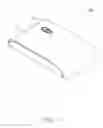
FIG. 1 is an isometric view of an electronic device in accordance with an exemplary embodiment.
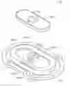
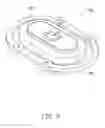
FIG. 2 is an isometric view of a button assembly used in the electronic device of FIG. 1.
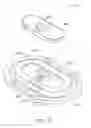
FIG. 3 is an isometric, exploded view of the button assembly of FIG. 2.
DETAILED DESCRIPTION
Embodiments of the present disclosure will now be described in detail below, with reference to the accompanying drawings.
Referring to FIG. 1, an electronic device 100 includes a main body 10 and at least one button assembly 20 mounted on the main body 10. An operation is performed when the button assembly 20 is depressed. For example, if the button 20 is a power button, powering on or off the electronic device 100 is performed when the button 20 is depressed. In this embodiment, the electronic device 100 is a computer host. In another embodiment, the electronic device 100 may be a display.
Referring to FIGS. 2-3, the button assembly 20 includes a base 201, a switch 202 mounted on the base 201, and a button 203 arranged on the switch 202. A raised logo 204 is set on the switch 202. A through hole 2031 matching with the logo 204 is set on the button 203 to receive the raised logo 204. When the button 203 is depressed, the switch 202 is actuated and sends a signal to a processing unit (not shown) of the electronic device 100. In this embodiment, the button 203 can be affixed on the switch 202 with glue when the raised logo 204 is received in the through hole 2031. The raised logo 204 and the switch 202 are integrally formed.
In this embodiment, the switch 202 is a power switch, and the raised logo 204 is a power logo. When the button 203 is depressed, the electronic device 100 is powered on or off.
In this embodiment, the raised logo 204 is made of transparent material. A first light source 2041 is arranged in the raised logo 204 to illuminate the raised logo 204 when the electronic device 100 is powered on. The button assembly 20 further includes a loop 205 arranged on the base 201 and around the button 203. The loop 205 is made of transparent material. A second light source 2051 is arranged in the loop 205 to illuminate the loop 205 to prompt the user where the button 203 is arranged.
Although the present disclosure has been specifically described on the basis of the exemplary embodiment thereof, the disclosure is not to be construed as being limited thereto. Various changes or modifications may be made to the embodiment without departing from the scope and spirit of the disclosure.
Claims
What is claimed is:1. A button assembly comprising:
a base;
a switch arranged on the base and comprising a raised logo arranged thereon; and
a button movably arranged on the switch, wherein a through hole is defined on the button to receive the raised logo.
2. The button assembly as described in claim 1, wherein the raised logo and the switch are integrally formed.
3. The button assembly as described in claim 1, wherein the raised logo is made of transparent material and a first light source is arranged in the raised logo to illuminate the logo.
4. The button assembly as described in claim 1 further comprising a loop arranged on the base and around the button, wherein the loop is made of transparent material, and a second light source is arranged in the loop to illuminate the loop.
5. The button assembly as described in claim 1, wherein the button is affixed on the switch with glue.
6. An electronic device comprising:
a main body; and
at least one button assembly comprising:
a base;
a switch arranged on the base and comprising a raised logo arranged thereon; and
a button arranged on the switch defining a through hole to receive the raised logo.
7. The electronic device as described in claim 6, wherein the raised logo and the switch are integrally formed.
8. The electronic device as described in claim 6, wherein the raised logo is made of transparent material and a first light source is arranged in the raised logo to illuminate the logo.
9. The electronic device as described in claim 6, wherein the button assembly further comprises a loop arranged on the base and around the button, the loop is made of transparent material, and a second light source is arranged in the loop to illuminate the loop.
10. The electronic device as described in claim 6, wherein the button is affixed on the switch with glue.
Images & Drawings included:
Sources:
- United States Patent and Trademark Office - verify current appl. status at the USPTO↗
Similar patent applications:
- » 20140065860
Slidable button assembly and electronic device using same - » 20140085781
BUTTON ASSEMBLY AND ELECTRONIC DEVICE USING THE SAME - » 20110094867
Power button assembly and electronic device using the same - » 20110094869
Power button assembly and electronic device using the same - » 20110114464
Power button assembly and electronic device using the same - » 20180174776
BUTTON ASSEMBLY AND ELECTRONIC DEVICE USING THE SAME - » 20120182673
PUSH-BUTTON ASSEMBLY AND ELECTRONIC DEVICE USING THE SAME - » 20090095613
Key button, key assembly using the key button and portable electronic device using the keypad assembly - » 20100025212
Key button and key assembly using the key button and portable electronic device using the keypad assembly - » 20120170234
Slide button, switching assembly, and electronic device using the same
Recent applications in this class:
- » 20230125225 2023-04-27
Keyboard - » 20210294387 2021-09-23
Button assembly, electronic device, and wearable device - » 20210026416 2021-01-28
Dynamic curvature devices and peripherals - » 20210026415 2021-01-28
CENTRALIZED CONTENT DISTRIBUTION IN A WEARABLE DISPLAY DEVICE NETWORK - » 20200293092 2020-09-17
Calculator having number keys for 3.663 and 6.336 - » 20190302853 2019-10-03
Memory aid - » 20190235581 2019-08-01
Centralized content distribution in a wearable display device network - » 20190064885 2019-02-28
Cover device, and electronic device and method for identifying cover device - » 20170083054 2017-03-23
Dome switch with noise-force dampening pad - » 20160170451 2016-06-16
Key retraction
Recent applications for this Assignee:
- » 20140233961 2014-08-21
Optical communication module including optical-electrical signal converters and optical signal generators - » 20140083669 2014-03-27
HEAT SINK - » 20140083669 2014-03-27
HEAT SINK - » 20140063746 2014-03-06
Electronic device with heat dissipation assembly - » 20140061224 2014-03-06
AUTOMATIC VENDING MACHINE - » 20140060914 2014-03-06
Enclosure with shield apparatus - » 20140058727 2014-02-27
MULTIMEDIA RECORDING SYSTEM AND METHOD - » 20140055955 2014-02-27
Fastener - » 20140055322 2014-02-27
DISPLAY SYSTEM AND HEAD-MOUNTED DISPLAY APPARATUS - » 20140054439 2014-02-27
CONTAINER DATA CENTER WITH SUPPORTING APPARATUS