DISASSEMBLY DEVICE
US20120324722A1
2012-12-27
13/210,344
2011-08-15
Abstract:
A disassembling device includes a plate, a number of suction cups, a number of fasteners, and a number of rods. The suction cups and the fasteners are respectively disposed at opposite sides of the plate to the fasteners. The plate includes a number of through holes. Each of the rods is fixed to one of the suction cups, the rods extend through the respective through holes, and is connected to the respective fasteners.
Inventors:
- KAI-KUEI WU 11 🇹🇼 Tu-Cheng, Taiwan
- KUN-CHIH HSIEH 35 🇹🇼 Tu-Cheng, Taiwan
- YONG-HUI HU 5 🇨🇳 Shenzhen City, China
- QING-QING ZHENG 3 🇨🇳 Shenzhen City, China
- TIAN-LEI WANG 2 🇨🇳 Shenzhen City, China
Assignee:
- HON HAI PRECISION INDUSTRY CO., LTD. 12,828 🇹🇼 Tu-Cheng, Taiwan
- HONG FU JIN PRECISION INDUSTRY (SHENZHEN) CO., LTD. 4,225 🇨🇳 Shenzhen City, China
Interested in similar patents?
Get notified when new applications in this technology area are published.
Classification:
B25B11/007 » CPC main
Work holders not covered by any preceding group in the subclass, e.g. magnetic work holders, vacuum work holders; Vacuum work holders portable, e.g. handheld
Y10T29/53274 » CPC further
Metal working; Means to assemble or disassemble Means to disassemble electrical device
B23P19/00 IPC
Machines for simply fitting together or separating metal parts or objects, or metal and non-metal parts, whether or not involving some deformation ; Tools or devices therefor so far as not provided for in other classes
Description
BACKGROUND
1. Technical Field
The present disclosure relates to a disassembly device, especially to a disassembly device for detaching covers from electronic devices.
2. Description of Related Art
During the manufacture of an electronic device including an upper cover and a lower cover, there may rise a need to detach the upper cover or the lower cover. For example, when needing to rework the device, the assembled upper cover may need to be detached. Because the upper cover and the lower cover are fixed to other members of the electronic device, an auxiliary tool for disassembling the upper cover and the lower cover is needed which is inconvenient.
BRIEF DESCRIPTION OF THE DRAWINGS
Many aspects of the embodiments can be better understood with reference to the following drawings. The components in the drawings are not necessarily drawn to scale, the emphasis instead being placed upon clearly illustrating the principles of the embodiments. Moreover, in the drawings, like reference numerals designate corresponding parts throughout the several views.
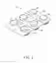
FIG. 1 is an isometric view of a disassembly device according to an exemplary embodiment.
FIG. 2 is similar to FIG. 1, but viewed from a different viewpoint.
FIG. 3 is an exploded view of the disassembling device in FIG. 1.
FIG. 4 is similar to FIG. 3, but viewed from a different viewpoint.
FIG. 5 is a cross-sectional view taken along line V-V of FIG. 1.
DETAILED DESCRIPTION
Referring to FIGS. 1 and 2, a disassembly device 10 according to an exemplary embodiment includes a plate 20, a number of fasteners 30, and a number of suction cups 40. The fasteners 30 and the suction cups 40 are respectively disposed at opposite sides of the plate 20. The plate 20 includes a handle 22 that can be gripped by an operator to push or pull the disassembly device 10.
Referring to FIGS. 3 and 4, each suction cup 40 includes a seat 42 protruding from a back side of the suction cup 40. A rod 50 protrudes from the top of each seat 42. Each rod 50 includes an external thread formed on a lateral surface thereof. In the embodiment, the rod 50 is integrally formed on the suction cup 40 by double shot molding. Each fastener 30 includes a sleeve 32 defining a threaded hole. The plate 20 further defines a number of through holes 24.
Referring to FIG. 5, the distal end of each rod 50 passes through a corresponding through hole 24 of the plate 20 and is screwed into the threaded hole of the corresponding sleeve 32. The seats 42 and the fasteners 30 respectively abut against opposite sides of the plate 20. When disassembling a cover from an electronic device (not shown), the suction cups 40 are put on the cover and a pushing force is exerted on the handle 22. The suction cups 40 are then deformed and the air in the suction cups 40 is expelled. As a result, the suction cups 40 firmly attach to the cover under vacuum. An operator can then grip the handle 22 to pull the cover until the cover is detached.
It is to be understood, however, that even though numerous characteristics and advantages of the present disclosure have been set forth in the foregoing description, together with details of the structure and function of the present disclosure, the present disclosure is illustrative only, and changes may be made in detail, especially in matters of shape, size, and arrangement of parts within the principles of the present disclosure to the full extent indicated by the broad general meaning of the terms in which the appended claims are expressed.
Claims
What is claimed is:1. A disassembly device comprising:
a plate defining a plurality of through holes;
a plurality of fasteners disposed at one side of the plate;
a plurality of suction cups disposed at an opposite side of the plate to the fasteners; and
a plurality of rods fixed to the respective suction cups, the rods extending through the respective through holes, and being connected to the respective fasteners.
2. The disassembly device of claim 1, wherein each of the suction cups comprises a seat protruding from a back side of the suction cup, the rod protrudes from the top of the seat, the seats and the fasteners respectively abut against the opposite sides of the plate.
3. The disassembly device of claim 1, wherein the rod is integrally formed on the suction cup by double shot molding.
Images & Drawings included:


Sources:
- United States Patent and Trademark Office - verify current appl. status at the USPTO↗
Similar patent applications:
- » 20160146559
Disassembly devices for use with firearms and firearms including such disassembly devices - » 20230380125
ELECTRONIC DEVICE, AND DISASSEMBLING DEVICE FOR DISASSEMBLING SAME - » 20060237230
DISASSEMBLY DEVICE FOR DISASSEMBLING A PRODUCT - » 20180093466
System for disassembling display device and method for disassembling display device using the same - » 20250114870
SOLAR PANEL DISASSEMBLY DEVICE AND SOLAR PANEL DISASSEMBLY METHOD USING THE SAME - » 20130266440
Compressor, assembling and disassembling device therefor, and assembling and disassembling method therefor - » 20090056097
Assembly and disassembly device for display monitor and method thereof - » 20090000099
Fast-disassembling device for anti-reversing plates of a cutting base of a table saw - » 20130174411
DISASSEMBLY METHOD AND DISASSEMBLY DEVICE FOR DISPLAY DEVICE - » 20120060363
Disassembling device
Recent applications in this class:
- » 20250114915 2025-04-10
WINDSCREEN INSTALLATION APPARATUS AND METHOD - » 20250001556 2025-01-02
MULTIFUNCTIONAL ELECTRIC SUCTION CUP - » 20240424646 2024-12-26
DIGITAL DISPLAY SUCTION CUP - » 20240278388 2024-08-22
VACUUM GRIPPER - » 20240246200 2024-07-25
Vacuum Gripper - » 20230294251 2023-09-21
Vacuum gripper - » 20230294250 2023-09-21
Windscreen installation apparatus and method - » 20220339762 2022-10-27
Vacuum gripper - » 20210299825 2021-09-30
Extension control handle for a portable grip device - » 20210276159 2021-09-09
Windscreen installation apparatus and method
Recent applications for this Assignee:
- » 20140233961 2014-08-21
Optical communication module including optical-electrical signal converters and optical signal generators - » 20140083669 2014-03-27
HEAT SINK - » 20140083669 2014-03-27
HEAT SINK - » 20140063746 2014-03-06
Electronic device with heat dissipation assembly - » 20140061224 2014-03-06
AUTOMATIC VENDING MACHINE - » 20140060914 2014-03-06
Enclosure with shield apparatus - » 20140058727 2014-02-27
MULTIMEDIA RECORDING SYSTEM AND METHOD - » 20140055955 2014-02-27
Fastener - » 20140055322 2014-02-27
DISPLAY SYSTEM AND HEAD-MOUNTED DISPLAY APPARATUS - » 20140054439 2014-02-27
CONTAINER DATA CENTER WITH SUPPORTING APPARATUS