Thermoelectric materials synthesized by self-propagating high temperature synthesis process and methods thereof
US20160059313A1
2016-03-03
14/441,446
2014-03-17
✅ Patent granted
US 10,500,642 B2
2019-12-10
WO; PCT/CN2014/000287; 20140317
WO; WO2014/146485; 20140925
Colleen P Dunn | Anthony M Liang
Hamre, Schumann, Mueller & Larson, P.C.
2036-10-16
Abstract:
The disclosure relates to thermoelectric materials prepared by self-propagating high temperature synthesis (SHS) process combining with Plasma activated sintering and methods for preparing thereof. More specifically, the present disclosure relates to the new criterion for combustion synthesis and the method for preparing the thermoelectric materials which meet the new criterion.
Inventors:
- Xinfeng Tang 8 🇨🇳 Wuhan, China
- Xianli Su 8 🇨🇳 Wuhan, China
- Qiang Zhang 14 🇨🇳 Wuhan, China
- Xin Cheng 9 🇨🇳 Wuhan, China
- Dongwang Yang 8 🇨🇳 Wuhan, China
- Gang Zheng 8 🇨🇳 Wuhan, China
- Fan Fu 8 🇨🇳 Wuhan, China
- Tao Liang 8 🇨🇳 Wuhan, China
- Qingjie Zhang 8 🇨🇳 Wuhan, China
Assignee:
- WUHAN UNIVERSITY OF TECHNOLOGY 8 🇨🇳 WUHAN, HUBEI, China
Applicant:
Interested in similar patents?
Get notified when new applications in this technology area are published.
Classification:
C22C1/02 » CPC further
Making alloys by melting
C22C1/0491 » CPC further
Making alloys by powder metallurgy comprising intermetallic compounds
B22F3/23 » CPC main
Manufacture of workpieces or articles from metallic powder characterised by the manner of compacting or sintering; Apparatus specially adapted therefor ; Presses and furnaces involving a self-propagating high-temperature synthesis or reaction sintering step
C22C1/04 IPC
Making alloys by powder metallurgy
B22F9/04 » CPC further
Making metallic powder or suspensions thereof using physical processes starting from solid material, e.g. by crushing, grinding or milling
C22C13/00 » CPC further
Alloys based on tin
C22C23/00 » CPC further
Alloys based on magnesium
C22C9/00 » CPC further
Alloys based on copper
C22C29/12 » CPC further
Alloys based on carbides, oxides, nitrides, borides, or silicides, e.g. cermets, or other metal compounds, e.g. oxynitrides, sulfides based on oxides
C22C28/00 » CPC further
Alloys based on a metal not provided for in groups -
B22F9/16 » CPC further
Making metallic powder or suspensions thereof using chemical processes
C22C11/00 » CPC further
Alloys based on lead
C22C12/00 » CPC further
Alloys based on antimony or bismuth
Description
FIELD
The present disclosure relates to thermoelectric materials prepared by self-propagating high temperature synthesis (SHS) process combining with plasma activated sintering (PAS) and a method for preparing the same. More specifically, the present disclosure relates to a new criterion for combustion synthesis and the method for preparing thermoelectric materials which can meet the new criterion.
BACKGROUND
In the heat flow of the energy consumption in the world, there is about 70% of the total energy wasted in the form of heat. If those large quantities of waste heat can be recycled effectively, it would relief the energy crisis in the world. Thermoelectric (TE) materials convert heat into electricity directly through the Seebeck effect. Thermoelectric materials offer many advantages including: no moving parts; small and lightweight; maintenance-free; no pollution; acoustically silent and electrically “quiet”. Thermoelectric energy conversion has drawn a great attention for applications in areas such as solar thermal conversion, industrial waste heat recovery. The efficiency of a TE material is strongly related to its dimensionless figure of merit ZT, defined as ZT=α2σT/κ, where α, σ; κ and T are the Seebeck coefficient, electrical conductivity, total thermal conductivity, and the absolute temperature, respectively. To achieve high efficiency, a large ZT is required. High electrical conductivity, large Seebeck coefficient, and low thermal conductivity are necessary for a high efficient TE material. However those three parameters relate with each other. Hence decoupling the connection of those parameters is key issue to improve the thermoelectric performance A lot of investigation shows that nanostructure engineering can weak the coupling to enhance the thermoelectric property.
Until now, most researchers have utilized top down approach to obtain nanostructure (mechanic alloy, melt spinning, etc). But all those processing is of high energy consumption. In addition, some investigator used bottom up fabrication to synthesize low dimensional material (Wet chemical method). Efficient synthesis and its adaptability to a large-scale industrial processing are important issues determining the economical viability of the fabrication process. So far, thermoelectric materials have been synthesized mostly by one of the following methods: melting followed by slow cooling; melting followed by long time annealing, multi-step solid state reactions, and mechanical alloying. Each such processing is time and energy consuming and not always easily scalable. Moreover, it is often very difficult to control the desired stoichiometry and microstructure. All those difficulty is of universality in all those thermoelectric material. Hence developing a technology which not only can synthesize the samples in large scale and short period but also can control the composition and microstructure precisely is of vital importance for the large scale application.
Self-propagating high-temperature synthesis (SHS) is a method for synthesizing compounds by exothermic reactions. The SHS method, often referred to also as the combustion synthesis, relies on the ability of highly exothermic reactions to be self-sustaining, i.e., once the reaction is initiated at one point of a mixture of reactants, it propagates through the rest of the mixture like a wave, leaving behind the reacted product. What drives this combustion wave is exothermic heat generated by an adjacent layer. In contrast with some other traditional method, the synthesis process is energy saving, exceptionally rapid and industrially scalable. Moreover, this method does not rely on any equipment. Base on the experiments, Merzhanov suggested an empirical criterion, Tad>1800 K, as the necessary precondition for self-sustainability of the combustion wave, where Tad is the maximum temperature to which the reacting compact is raised as the combustion wave passes through. It restricts the scope of materials that can be successfully synthesized by SHS processing.
SUMMARY
In order to solve the problem of existing technology, the objects of the present disclosure is to provide an ultra-fast fabrication method for preparing high performance thermoelectric materials. By using this method, it can control the composition very precisely, shorts the synthesis period, and is easy to scale up to kilogram. High thermoelectric performance can be obtained. Moreover, we found that the criterion often quoted in the literature as the necessary precondition for self-sustainability of the combustion wave, Tad≧1800 K, where Tad is the maximum temperature to which the reacting compact is raised as the combustion wave passes through, is not universal and certainly not applicable to thermoelectric compound semiconductors. Instead, we offer new empirically-based criterion, Tad/TmL>1, i.e., the adiabatic temperature must be high enough to melt the lower melting point component. This new criterion covers all materials synthesized by SHS, including the high temperature refractory compounds for which the Tad≧1800 K criterion was originally developed. Our work opens a new avenue for ultra-fast, low cost, mass production fabrication of efficient thermoelectric materials and the new insight into the combustion process greatly broadens the scope of materials that can be successfully synthesized by SHS processing.
In accordance with the present disclosure, the above objects of the present disclosure can be achieved by the following steps.
1. The new criterion for the combustion synthesis of binary compounds is as following.
1) The adiabatic temperatures Tad of the binary compounds are calculated by thermodynamic data (enthalpy of formation and the molar specific heat of the product) and Eq. (1). Where ΔfH298K is enthalpy of formation for the binary compounds, T is temperature, H298K0 is the enthalpy of the binary compounds at 298 K, and C is the molar specific heat of the product and the integral includes latent heats of melting, vaporization, and phase transitions, if any present. The reactants for the combustion reaction are pure elemental for the binary compounds.
−ΔfH298K=HT0−H298K0=∫298KTadCdT (1)
When there is no phase transition and the adiabatic temperature is lower than the melting point of the binary compound, Equation (1) can be simplified into Equation (2) shown below, where Cp is the the molar specific heat of the product in solid state.
−ΔfH298K=HT0−H298K0=∫298KTadCpdT (2)
When there is no phase transition and the adiabatic temperature is higher than the melting point of the binary compound and lower than the boiling point of of the binary compound, Equation (1) can be simplified into Equation (3) shown below, where Cp, C″p is the the molar specific heat of the product in solid state and liquid state respectively, T., is the melting point of the binary compound, ΔHm is the enthalpy change during fusion processing.
−ΔfH298K=HT0−H298K0=∫298KTadCpdT+ΔHm+∫TmTadC″pdT (3)
When there is no phase transition and the adiabatic temperature is higher than the boiling point of of the binary compound, Equation (1) can be simplified into Equation (4) shown below, where Cp, C″p, C′″p is the the molar specific heat of the product in solid, liquid and gaseous state respectively, Tm, Tb is the melting point and boiling point of the binary compound, respectively. ΔHm, ΔHb is the enthalpy change during fusion and gasification processing repectively.
−ΔfH298K=HT0−H298K0=∫298KTadCpdT+ΔHm+∫TmTRC″pdT+ΔHB+∫TBTadC″pdT (4)
When phase transition exists during the heating processing and the adiabatic temperature is higher than the phase transition temperature of the binary compound, the Equation (1) can be simplified into Equation (5) as below, where Cp, C′p is the the molar specific heat of the product in solid before or after phase transition respectively, Ttr is the phase transition temperature of the binary compound, A Htr is the enthalpy change during phase transition processing.
−ΔfH298K=HT0−H298K0=∫298KtuCpdT+ΔHtr+∫TrTmC′pdT+ΔHm+∫TmaddT (5)
When phase transition exists during the heating processing and the adiabatic temperature is higher than the phase transition temperature and the melting point of the binary compound, the Equation (1) can be simplified into Equation (6) as below, where Cp, C′p, C″p is the molar specific heat of the product in solid before or after phase transition and the molar specific heat of the product in liquid state respectively, Ttr, Tm is the phase transition temperature and melting point of the binary compound respectively, ΔHtr, ΔHm is the enthalpy change during phase transition processing and fusion processing.
−ΔfH298K=HT0−H298K0=∫298KtuCpdT+ΔHtr+∫TtrTmC′pdT+ΔHm+∫TmTadC″pdT (6)
When phase transition exists during the heating processing and the adiabatic temperature is higher than the phase transition temperature and the boiling point of the binary compound, the Equation (1) can be simplified into Equation (7) as below, where Cp, C′p, C″p is the molar specific heat of the product in solid before or after phase transition and the molar specific heat of the product in liquid state respectively, Ttr, Tm is the phase transition temperature and melting point of the binary compound respectively, ΔHtr, ΔHm is the enthalpy change during phase transition processing and fusion processing.
−ΔfH298K=HT0−H298K0=∫298KtuCpdT+ΔHtr+∫TtrTmC′pdT+ΔHm+∫TmTBC″pdT+ΔHB+∫TbTadC′″pdT (7)
2. TmL represents the melting point of the component with lower melting point. The SHS reaction to be self-sustaining, the value of Tad/Tm,L should be more than 1, i.e., the heat released in the reaction must be high enough to melt the component with the lower melting point, or the combustion wave can not be self propagated.
3. Based on the new criterion for combustion synthesis of thermoelectric compounds, the above and other objects can be accomplished by the provision of a method for preparing thermoelectric materials by SHS combining Plasma activated sintering which comprises following steps:
-
- 1) Choose two single elemental as the starting material for the reaction
- 2) The adiabatic temperatures Tad of the binary compounds are calculated by thermodynamic data (enthalpy of formation and the molar specific heat of the product) and Eq. (1). Where ΔfH298K is enthalpy of formation for the binary compounds, T is temperature, H298K0 is the enthalpy of the binary compounds at 298 K, and C is the molar specific heat of the product and the integral includes latent heats of melting, vaporization, and phase transitions, if any present. The reactants for the combustion reaction are pure elemental for the binary compounds.
−ΔfH298K=HT0−H298K0=∫298KTadCdT (1)
When there is no phase transition and the adiabatic temperature is lower than the melting point of the binary compound, the Equation (1) can be simplified into Equation (2) as below, where Cp is the the molar specific heat of the product in solid state.
−ΔfH298K=HT0−H298K0=∫298KTadCpdT (1)
When there is no phase transition and the adiabatic temperature is higher than the melting point of the binary compound and lower than the boiling point of of the binary compound, the Equation (1) can be simplified into Equation (3) as below, where Cp, C″p is the the molar specific heat of the product in solid state and liquid state respectively, Tm is the melting point of the binary compound, ΔHm is the enthalpy change during fusion processing.
−ΔfH298K=HT0−H298K0=∫298KTmCpdT+ΔHm+∫TmTadC″pdT (3)
When there is no phase transition and the adiabatic temperature is higher than the boiling point of of the binary compound, the Equation (1) can be simplified into Equation (4) as below, where Cp, C″p, C′″p is the the molar specific heat of the product in solid, liquid and gaseous state respectively, Tm, Tb is the melting point and boiling point of the binary compound, respectively. ΔHm, ΔHb is the enthalpy change during fusion and gasification processing repectively.
−ΔfH298K=HT0−H298K0=∫298KTmCpdT+ΔHm+∫TmTBC″pdT+ΔHH+∫TB (4)
When phase transition exists during the heating processing and the adiabatic temperature is higher than the phase transition temperature of the binary compound, the Equation (1) can be simplified into Equation (5) as below, where Cp, C′p is the the molar specific heat of the product in solid before or after phase transition respectively, Ttr is the phase transition temperature of the binary compound, ΔHtr is the enthalpy change during phase transition processing.
−ΔfH298K=HT0−H298K0=∫298KTmCpdT+ΔHtr+∫TtrTadC′pdT (3)
When phase transition exists during the heating processing and the adiabatic temperature is higher than the phase transition temperature and the melting point of the binary compound, the Equation (1) can be simplified into Equation (6) as below, where Cp, Cp, C″p is the molar specific heat of the product in solid before or after phase transition and the molar specific heat of the product in liquid state respectively, Ttr, Tm is the phase transition temperature and melting point of the binary compound respectively, ΔHtr, ΔHm is the enthalpy change during phase transition processing and fusion processing.
−ΔfH298K=HT0−H298K0=∫298KTtrCpdT+ΔHtr+∫TtrTmC′pdT+ΔHm+∫TmTadC″pdT (3)
When phase transition exists during the heating processing and the adiabatic temperature is higher than the phase transition temperature and the boiling point of the binary compound, the Equation (1) can be simplified into Equation (7) as below, where Cp, C′p, C ″p is the molar specific heat of the product in solid before or after phase transition and the molar specific heat of the product in liquid state respectively, Ttr, Tm is the phase transition temperature and melting point of the binary compound respectively, ΔHtr, ΔHm is the enthalpy change during phase transition processing and fusion processing.
−ΔfH298K=HT0−H298K0=∫298KTtrCpdT+ΔHtr+∫TtrTmC′pdT+ΔHm+∫TmTBC″pdT+ΔHB+∫TTbTadC′″pdT (7)
-
- 3) TmL represents the melting point of the component with lower melting point. The SHS reaction to be self-sustaining, the value of Tad/Tm,L should be more than 1, i.e., the heat released in the reaction must be high enough to melt the component with the lower melting point, or the combustion wave can not be self propagated.
- 4) Self propagating high temperature synthesis: Stoichiometric amounts of single elemental powders with high purity were weighed and mixed in the agate mortar and then cold-pressed into a pellet. The pellet obtained was initiated by point-heating a small part (usually the bottom) of the sample. Once started, a wave of exothermic reactions (combustion wave) passes through the remaining material as the liberated heat of fusion in one section is sufficient to maintain the reaction in the neighboring section of the compact. And then the pellet was cool down to room temperature in the air. Single phase binary compounds are obtained after SHS.
- According to the above step, the binary compounds are mostly thermoelectric material, high temperature ceramics and intermetallic.
According to the above step, the purity of the single elemental powder is better than 99.99%.
-
- According to the above step, the pellet was sealed in a silica tube under the pressure of 10−3 Pa or Ar atmosphere. The components react under the pressure of 10−3 Pa or Ar atmosphere.
According to the above step, the pellet after SHS was crushed into powders and then sintered by spark plasma sintering to obtain the bulks.
Moreover, we found that the criterion suggested by Merzhanov as the necessary precondition for self-sustainability of the combustion wave, Tad≧1800 K, where Tad is the maximum temperature to which the reacting compact is raised as the combustion wave passes through, is not universal and certainly not applicable to thermoelectric compound semiconductors. Instead, we offer new empirically-based criterion, Tad/TmL>1, i.e., the adiabatic temperature must be high enough to melt the lower melting point component. When this happens, the higher melting point component rapidly dissolves in the liquid phase of the first component and generates heat at a rate high enough to sustain propagation of the combustion wave. This new criterion covers all materials synthesized by SHS, including the high temperature refractory compounds for which the Tad≧1800 K criterion was originally developed. Our work opens a new avenue for ultra-fast, low cost, mass production fabrication of efficient thermoelectric materials and the new insight into the combustion process greatly broadens the scope of materials that can be successfully synthesized by SHS processing.
It is another object for present disclosure to provide a method for preparing ternary or quarternary thermoelectric materials. Choose elemental powder with high purity as the starting material for the reaction. Stoichiometric amounts of single elemental powders with high purity were weighed and mixed in the agate mortar and then cold-pressed into a pellet. The pellet obtained was initiated by point-heating a small part (usually the bottom) of the sample. Once started, a wave of exothermic reactions (combustion wave) passes through the remaining material as the liberated heat of fusion in one section is sufficient to maintain the reaction in the neighboring section of the compact. And then the pellet was cool down to room temperature in the air. Single phase compounds are obtained after SHS. The pellet was crushed into powder and then sintered by spark plasma sintering to obtain the bulk thermoelectric materials. The detailed synthesis procedure for ternary or quarternary thermoelectric materials is as following.
The ultra-fast synthesis method for preparing high performance Half-Heusler thermoelectric materials with low cost comprises the steps of
-
- 1) Stoichiometric amounts ABX of high purity single elemental A, B, X powders were weighed and mixed in the agate mortar and then cold-pressed into a pellet.
- 2) The pellet was sealed in a silica tube under the pressure of 10−3 Pa and was initiated by point-heating a small part (usually the bottom) of the sample. Once started, a wave of exothermic reactions (combustion wave) passes through the remaining material as the liberated heat of fusion in one section is sufficient to maintain the reaction in the neighboring section of the compact. And then the pellet was cool down to room temperature in the air or quenched in the salt water.
- 3) The obtained pellet in step 2) was crushed, hand ground into a fine powder, and then sintered by PAS. The densely bulks half heusler with excellent thermoelectric properties is obtained after PAS.
In step 1), what we choose for elemental A can be the elemental in IIIB, IVB, and VB column of periodic Table, Such as one of or the mixture of the Ti, Zr, Hf, Sc, Y, La, V, Nb, Ta. What we choose for elemental B can be the elemental in VIIIB column of periodic Table, such as one of or the mixture of the Fe, Co, Ni, Ru, Rh, Pd, and Pt. What we choose for elemental B can be the elemental in IIIA, IVA, VA column of periodic Table, such as one of or the mixture of the Sn, Sb, and Bi. In step 3), the parameter for spark plasma sintering is with the temperature above 850° C. and the pressure around 30-50 MPa.
The detail of the ultra-fast preparation method of high performance BiCuSeO based thermoelectric material is as following.
-
- 1) Weigh Bi2O3, PbO, Bi, Cu, and Se according to the stoichiometric ratio (1-p):3p:(1-p):3:3(p=0, 0.02, 0.04, 0.06, 0.08, 0.1) and mix them in the agate mortar and then cold-pressed into a pellet.
- 2) The pellet obtained in step 1) was sealed in a silica tube under the pressure of 10−3Pa and was initiated by point-heating a small part (usually the bottom) of the sample. Once started, a wave of exothermic reactions (combustion wave) passes through the remaining material as the liberated heat of fusion in one section is sufficient to maintain the reaction in the neighboring section of the compact. And then the pellet was cool down to room temperature in the air or quenched in the salt water.
- 3) The obtained pellet Bi1-pPbpCuSe in step 2) was crushed, hand ground into a fine powder, and then sintered by PAS. The densely bulks Bi1-pPbpCuSe with excellent thermoelectric properties is obtained after PAS.
In step 3), the parameter for spark plasma sintering is with the temperature above 670° C. and the pressure of 30MPa holding for 5-7 min.
The detail of the ultra-fast preparation method of high performance Bi2Te3 based thermoelectric material is as following.
-
- 1) Stoichiometric amounts Bi2Te3-xSex of high purity single elemental Bi, Te, Se powders were weighed and mixed in the agate mortar and then cold-pressed into a pellet.
- 2) The pellet obtained in step 1) was sealed in a silica tube under the pressure of 10−3 Pa and was initiated by point-heating a small part (usually the bottom) of the sample. Once started, a wave of exothermic reactions (combustion wave) passes through the remaining material as the liberated heat of fusion in one section is sufficient to maintain the reaction in the neighboring section of the compact. And then the pellet was cool down to room temperature in the air or quenched in the salt water.
- 3) The obtained pellet Bi2Te3-xSex in step 2) was crushed, hand ground into a fine powder, and then sintered by PAS. The densely bulks Bi2Te3-xSex with excellent thermoelectric properties is obtained after PAS.
In step 3), load the Bi2Te3-xSex powder with single phase into the graph die. the parameter for spark plasma sintering is with the temperature around 420-480° C. and the pressure of 20 MPa holding for 5 min.
The detail of the ultra-fast preparation method of high performance PbS1-xSex thermoelectric material is as following.
-
- 1) Stoichiometric amounts PbS1-xSex of high purity single elemental Pb, S, Se powders were weighed and mixed in the agate mortar and then cold-pressed into a pellet.
- 2) The pellet obtained in step 1) was sealed in a silica tube under the pressure of 10−3 Pa and was initiated by point-heating a small part (usually the bottom) of the sample. Once started, a wave of exothermic reactions (combustion wave) passes through the remaining material as the liberated heat of fusion in one section is sufficient to maintain the reaction in the neighboring section of the compact. And then the pellet was cool down to room temperature in the air or quenched in the salt water.
- 3) The obtained pellet PbS1-xSex in step 2) was crushed, hand ground into a fine powder, and then sintered by PAS. The densely bulks PbS1-xSex with excellent thermoelectric properties is obtained after PAS.
In step 3), load the PbS1-xSex powder with single phase into the graphite die. The parameter for spark plasma sintering is with the temperature of 550° C. and the pressure of 35 MPa holding for 7 min.
The detail of the ultra-fast preparation method of high performance Mg2Si based thermoelectric material is as following.
-
- 1) Stoichiometric amounts Mg2(1+002)Si1-nSbn(0≦n≦0.025) of high purity single elemental Mg, Si,
Sb powders were weighed and mixed in the agate mortar and then cold-pressed into a pellet.
-
- 2) The pellet obtained in step 1) was sealed in a silica tube under the pressure of 10−3 Pa and was initiated by point-heating a small part (usually the bottom) of the sample. Once started, a wave of exothermic reactions (combustion wave) passes through the remaining material as the liberated heat of fusion in one section is sufficient to maintain the reaction in the neighboring section of the compact. And then the pellet was cool down to room temperature in the air or quenched in the salt water.
- 3) The obtained pellet Mg2(1+002)Si1-nSbn(0≦n≦0.025) in step 2) was crushed, hand ground into a fine powder, and then sintered by PAS. The densely bulks PbS1-xSex with excellent thermoelectric properties is obtained after PAS.
In step 3), load the Mg2(1+002)Si1-nSbn(0≦n≦0.025) powder with single phase into the graphite die. The parameter for spark plasma sintering is with the temperature of 800° C. with the heating rate 100° C./min and the pressure of 33 MPa holding for 7 min. Since the content of Sb in Mg2(1+002)Si1-nSbn(0≦n≦0.025) is very low, the impact of Sb on the SHS processing can be ignored.
The detail of the ultra-fast preparation method of high performance CuaMSnbSe4 thermoelectric material is as following.
-
- 1) Stoichiometric amounts CuaMSnbSe4 (M=Sb, Zn, or Cd; a=2 or 3; b=1 or 0) of high purity single elemental Cu, M, Sn, Se powders were weighed and mixed in the agate mortar and then cold-pressed into a pellet. For Cu3SbSe4, Weigh the elemental Cu, Sb Se powder according to the ratio of Cu:Sb:Se=3: (1.01˜1.02):4, and mixed in the agate mortar and then cold-pressed into a pellet. For Cu2ZnSnSe4, Weigh the elemental Cu, Zn, Sn, Se powder according to the ratio of Cu:Zn:Sn:Se=2:1:1:4, and mixed in the agate mortar and then cold-pressed into a pellet. For Cu2CdSnSe4, Weigh the elemental Cu, Cd, Sn, Se powder according to the ratio of Cu:Cd:SN;Se=2:1:1:4, and mixed in the agate mortar and then cold-pressed into a pellet.
- 2) The pellet obtained in step 1) was sealed in a silica tube under the pressure of 10-3 Pa and was initiated by point-heating a small part (usually the bottom) of the sample. Once started, a wave of exothermic reactions (combustion wave) passes through the remaining material as the liberated heat of fusion in one section is sufficient to maintain the reaction in the neighboring section of the compact. And then the pellet was cool down to room temperature in the air or quenched in the salt water. The obtained pellet CuaMSnbSe4 in step 2) was crushed, hand ground into a fine powder.
The detail of the ultra-fast preparation method of high performance Cu2SnSe3 thermoelectric material is as following.
-
- 1) Weigh high purity single elemental Cu, Sn, Se powders according to the ratio of Cu:Se:Sn=2.02: 3.03: 1 and mixed in the agate mortar and then cold-pressed into a pellet.
- 2) The pellet obtained in step 1) was sealed in a silica tube under the pressure of 10−3 Pa and was initiated by point-heating a small part (usually the bottom) of the sample. Once started, a wave of exothermic reactions (combustion wave) passes through the remaining material as the liberated heat of fusion in one section is sufficient to maintain the reaction in the neighboring section of the compact. And then the pellet was cool down to room temperature in the air or quenched in the salt water.
- 3) The obtained pellet Cu2SnSe3 in step 2) was crushed, hand ground into a fine powder, and then sintered by PAS. The densely bulks Cu2SnSe3 with excellent thermoelectric properties is obtained after PAS.
In step 3), load the Cu2SnSe3 powder with single phase into the graphite die. The parameter for spark plasma sintering is with the temperature around 500-550° C. with the heating rate 50-100° C./min and the pressure around 30-35 MPa holding for 5-7 min.
The detail of the ultra-fast preparation method of high performance CoSb3 based thermoelectric material is as following.
-
- 1) Stoichiometric amounts Co4-eMeSb12-fTef (0≦e≦1.0, 0≦f≦1.0, M═Fe or Ni) of high purity single elemental Co, M, Sb, Te powders were weighed and mixed in the agate mortar and then cold-pressed into a pellet.
- 2) The pellet obtained in step 1) was sealed in a silica tube under the pressure of 10−3 Pa and was initiated by point-heating a small part (usually the bottom) of the sample. Once started, a wave of exothermic reactions (combustion wave) passes through the remaining material as the liberated heat of fusion in one section is sufficient to maintain the reaction in the neighboring section of the compact. And then the pellet was cool down to room temperature in the air or quenched in the salt water.
- 3) The obtained pellet Co4-eMeSb12-fTef (0≦e≦1.0, 0≦f≦1.0, M═Fe or Ni) in step 2) was crushed, hand ground into a fine powder, and then sintered by PAS. The densely bulks Co4-eMeSb12-fTef (0≦e≦1.0, 0≦f≦1.0, M═Fe or Ni) with excellent thermoelectric properties is obtained after PAS.
In step 3), load the Co4-eMeSb12-fTef (0≦e≦1.0, 0≦f≦1.0, M═Fe or Ni) powder with single phase into the graphite die. The parameter for spark plasma sintering is with the temperature of 650° C. with the heating rate 100° C./min and the pressure of 40 MPa holding for 8 min.
Compared with the convetional synthesis technique, the advantage of the disclosure is as below.
-
- 1. SHS method is very convenient and does not rely on any equipment. But for some other methods such as Mechanic alloy, Melt spinning, etc all those processing demand complicated equipments. For chemical method, the yield is very low and it is very difficult to condense the sample. Moreover all those processing except SHS processing is energy consuming Self-propagating high-temperature synthesis (SHS) is a method for synthesizing compounds by exothermic reactions. The SHS method, often referred to also as the combustion synthesis, relies on the ability of highly exothermic reactions to be self-sustaining, i.e., once the reaction is initiated at one point of a mixture of reactants, it propagates through the rest of the mixture like a wave, leaving behind the reacted product. What drives this combustion wave is exothermic heat generated by an adjacent layer. In contrast with some other traditional method, the synthesis process is energy saving, exceptionally rapid and industrially scalable.
- 2. Since Self-propagating high-temperature synthesis (SHS) can be finished in a very short time. It can control the composition very precisely. Moreover, the Non-equibrium microstructure can be obtained since large temperature gradient exists during the SHS processing.
- 3. It shortens the synthesis periods very significantly by about 90% in comparson with conventional method.
Based on the above content, without departing from the basic technical concept of the present disclosure, under the premise of ordinary skill in the art based on the knowledge and means of its contents can also have various forms of modification, substitution or changes, such as Tad>TmL, or TmL<Tad.
BRIEF DESCRIPTION OF THE DRAWING
FIG. 1 shows Powder XRD pattern of compounds thermoelectric after SHS for embodiment example 1.
FIG. 2 shows Powder XRD pattern of Sb2Te3 and MnSi1.70 pellets after SHS in different region for embodiment example 2.
FIG. 3 shows the ratio of between Tad and TmL for compounds thermoelectrics PbS, PbSe, Mg2Si, Mg2Sn, Cu2Se, Bi2Se3, PbTe, Bi2Te3 in embodiment example 1 and high temperature intermetallic and refractory in embodiment example 3.
FIG. 4 shows XRD pattern of Cu2Se after SHS (in step 2) and after SHS-PAS (in step 3) of embodiment example 4
FIG. 5 shows FESEM image of Cu2Se after SHS (in step 2) of embodiment example 4
FIG. 6 shows FESEM image of Cu2Se after SHS-PAS (in step 3) of embodiment example 4
FIG. 7 shows the temperature dependence of ZT (in step 3) of embodiment example 4.
FIG. 8 shows XRD pattern of the powder in step 2 of embodiment example 5.1 and bulk in step 3 of embodiment example 5.1
FIG. 9 shows the microstructure of the powder in step 2 of embodiment example 5.1.
FIG. 10 shows XRD pattern of the powder in step 2 of embodiment example 5.2
FIG. 11 shows the XRD pattern of the powder in step 2 of embodiment example 5.3 and bulk in step 3 of embodiment example 5.3
FIG. 12 shows the temperature dependence of power factor and ZT of bulks obtained in step 3 of embodiment example 5.3
FIG. 13 shows the XRD pattern of the powder obtained in step 2 of embodiment example 6
FIG. 14 shows the XRD pattern of the Bi2Te2.7Se0.3 compound in step 2 of embodiment example 7.1 and Bi2Te2.7Se0.3 bulk in step 3 of embodiment example 7.1
FIG. 15(a) shows FESEM image of Bi2Te2.7Se0.3 after SHS-PAS (in step 3) of embodiment example 7.1. FIG. 15(b) shows enlarged FESEM image of Bi2Te2.7Se0.3 after SHS-PAS.
FIG. 16 shows temperature dependence of ZT for Bi2Te2.7Se0.3 compound (in step 3) of embodiment example 7.1 and the data from the reference.
FIG. 17 shows the XRD pattern of the Bi2Te2.7Se0.3 compound in step 2 of embodiment example 7.2
FIG. 18 shows the XRD pattern of the Bi2Te2Se compound in step 2 of embodiment example 7.3
FIG. 19 shows the XRD pattern of powder after SHS in embodiment example 8.1
FIG. 20 shows the XRD pattern of powder after SHS and after SHS-PAS of embodiment example 8.2
FIG. 21 shows the XRD pattern of powder after SHS in embodiment example 8.3
FIG. 22 shows the XRD pattern of powder after SHS in embodiment example 8.4
FIG. 23(a) shows the XRD pattern of powder after SHS and after SHS-PAS of embodiment example 8.5. FIG. 23(b) shows SEM image of the powder after SHS (with the magnification5000 and 8000) in embodiment example 8.4. FIG. 23(c) shows the temperature dependence of ZT in compareson with the sample synthesized by melting method in embodiment example 8.4.
FIG. 24(a) shows the XRD pattern of powder after SHS and after SHS-PAS of embodiment example 9.1. FIG. 24(b) shows SEM image of the powder after SHS (with the magnification5000 and 10000) in embodiment example 9.1. FIG. 24(c) shows SEM image of the bulks after SHS-PAS (with the magnification 2000 and 10000) in embodiment example 9.1.
FIG. 25(a) shows the XRD pattern of powder after SHS and after SHS-PAS of embodiment example 9.2. FIG. 25(b) shows SEM image of the powder after SHS (with the magnification5000 and 10000) in embodiment example 9.2. FIG. 25(c) shows SEM image of the bulks after SHS-PAS (with the magnification 2000 and 10000) in embodiment example 9.2.
FIG. 26(a) shows the XRD pattern of powder after SHS and after SHS-PAS of embodiment example 9.3. FIG. 26(b) shows SEM image of the powder after SHS (with the magnification5000 and 10000) in embodiment example 9.3. FIG. 26(c) shows SEM image of the bulks after SHS-PAS (with the magnification 2000 and 10000) in embodiment example 9.3.
FIG. 27(a) shows the XRD pattern of powder after SHS and after SHS-PAS of embodiment example 9.4. FIG. 27(b) shows SEM image of the powder after SHS (with the magnification 5000 and 10000) in embodiment example 9.4. FIG. 27(c) shows SEM image of the bulks after SHS-PAS (with the magnification 2000 and 10000) in embodiment example 9.4.
FIG. 28(a) shows the XRD pattern of powder after SHS and after SHS-PAS of embodiment example 9.5. FIG. 28(b) shows SEM image of the powder after SHS (with the magnification 5000 and 10000) in embodiment example 9.5. FIG. 28(c) shows SEM image of the bulks after SHS-PAS (with the magnification 2000 and 10000) in embodiment example 9.5. FIG. 28(d) shows the temperature dependence of ZT in compareson with the sample synthesized by other method in embodiment example 9.5.
FIG. 29 shows the XRD pattern of Cu3SbSe4 powder after SHS in step 3 of embodiment example 10.1.
FIG. 30 shows the XRD pattern of Cu3SbSe4 powder after SHS in step 3 of embodiment example 10.2.
FIG. 31 shows the XRD pattern of Cu2ZnSnSe4 powder after SHS in step 3 of embodiment example 10.3.
FIG. 32 shows the XRD pattern of Cu2ZnSnSe4 powder after SHS in step 3 of embodiment example 10.4.
FIG. 33 shows the XRD pattern of Cu2CdSnSe4 powder after SHS in step 3 of embodiment example 10.5.
FIG. 34 shows the XRD pattern of Cu3SbSe4 powder after SHS in step 3 of embodiment example 10.6.
FIG. 35 shows the XRD pattern of Cu2SnSe3 powder after SHS in step 2 of embodiment example 11.1
FIG. 36 shows the XRD pattern of Cu2SnSe3 powder after SHS in step 2 of embodiment example 11.2
FIG. 37 shows the XRD pattern of Cu2SnSe3 powder after SHS-PAS of embodiment example 11.2
FIG. 38 shows the temperature dependence of ZT for Cu2SnSe3 in embodiment example 11.2
FIG. 39 shows the XRD pattern of Cu2SnSe3 powder after SHS in embodiment example 11.3
FIG. 40(a) shows the XRD pattern of powder after SHS and after SHS-PAS of embodiment example 12.1. FIG. 40(b) shows SEM image of the powder after SHS (with the magnification 5000 and 20000) in step 2 of embodiment example 12.1. FIG. 40(c) shows SEM image of the bulks after SHS-PAS (with the magnification 5000 and 20000) in step 3 of embodiment example 12.1.
FIG. 41(a) shows the XRD pattern of powder after SHS and after SHS-PAS of embodiment example 12.2. FIG. 41(b) shows SEM image of the powder after SHS (with the magnification 5000 and 20000) in step 2 of embodiment example 12.2. FIG. 41(c) shows SEM image of the bulks after SHS-PAS (with the magnification 5000 and 20000) in step 3 of embodiment example 12.2.
FIG. 42(a) shows the XRD pattern of powder after SHS and after SHS-PAS of embodiment example 12.3. FIG. 42(b) shows SEM image of the powder after SHS (with the magnification 5000 and 20000) in step 2 of embodiment example 12.3. FIG. 42(c) shows SEM image of the bulks after SHS-PAS (with the magnification 5000 and 20000) in step 3 of embodiment example 12.3.
FIG. 43(a) shows the XRD pattern of powder after SHS and after SHS-PAS of embodiment example 12.4. FIG. 43(b) shows SEM image of the powder after SHS (with the magnification 5000 and 20000) in step 2 of embodiment example 12.4. FIG. 43(c) shows SEM image of the bulks after SHS-PAS (with the magnification 5000 and 20000) in step 3 of embodiment example 12.4.
FIG. 44(a) shows the XRD pattern of powder after SHS and after SHS-PAS of embodiment example 12.5. FIG. 44(b) shows SEM image of the powder after SHS (with the magnification 5000 and 20000) in step 2 of embodiment example 12.5. FIG. 44(c) shows SEM image of the bulks after SHS-PAS (with the magnification 5000 and 20000) in step 3 of embodiment example 12.5.
FIG. 45(a) shows the temperature dependence of ZT for Co3.5Ni0.5Sb12 in step 3 of embodiment example 12.1 compared with the data from reference.(in the reference, the sample synthesized by Melt-annealing and PAS. It takes about 240 h)
FIG. 45(b) shows the temperature dependence of ZT for Co4Sb11.4Te0.6 in step 3 of embodiment example 12.5 compared with the data from reference. (In the reference, the sample is synthesized by Melt-annealing and PAS. It takes about 168 h)
DETAILED DESCRIPTION
For a better understanding of the present disclosure, several embodiments are given to further illustrate the disclosure, but the present disclosure is not limited to the following embodiments
Embodiment Example 1
Embodiment Example 1.1
Based on the new criterion, the detailed synthesis procedure of Bi2Te3 is as following.
(1) Elemental Bi, Te powder with high purity were Chosen as starting material.
(2) The adiabatic temperature can be calculated by using molar enthalpy of forming Bi2Te3 and the molar heat capacity according to the following formula. The molar enthalpy of forming Bi2Te3 at 298K ΔfH298K is −78.659 kJ.mol−1
−ΔfH298K=HT0−H298K0=∫298KTadCdt
Assuming the adiabatic temperature is lower than the melting point of Bi2Te3, there is no phase transition during the combustion processing. The above formula can be simplified as below.
−ΔfH298K=HT0−H298K0=∫298KTadCpdT
The molar heat capacity of Bi2Te3 in solid state is 107.989+55.229×10⁻³T JK−1 mol−1, solve the equation and then the adiabatic temperature can be obtained as 860 K. Since the calculated adiabatic temperature is 860 K, which is lower than the melting point of Bi2Te3. The result obtained is consistent with the assumpation. Hence the adiabatic temperature is 860 K.
Δ f H 298 K 0 = - 78.659 kJ mol - 1 = - ∫ 298 K T ad ( 107.989 + 55.229 × 10 - 3 T ) T = - [ 107.989 × ( T ad - 298 ) + 0.5 × 55.229 × 10 - 3 × ( T ad 2 - 298 2 ) ]
(3) Since the molten point of Te and Bi is 722.5 K, 544.44 K respectively. The component with lower melting point is Bi. The ratio between the adiabatic temperature and the melting point of the component with lower melting point is 1.58. According to the new criterion for combustion synthesis, self propogating high temperature reaction between Bi and Te can be self sustained.
(4) The SHS synthesis of Bi2Te3 can be achieved by the following steps.
a) Stoichiometric amounts of high purity Bi(4N), and Te(4N) powders were weighed and mixed in the agate mortar and then cold-pressed into a pellet with the dimension of φ15×18 mm under the pressure 8 MPa holding for 10 min.
b) The pellet obtained in the step a) was sealed in a silica tube under the pressure of 10−3 Pa and was initiated by point-heating a small part (usually the bottom) of the sample. Once started, a wave of exothermic reactions (combustion wave) passes through the remaining material as the liberated heat of fusion in one section is sufficient to maintain the reaction in the neighboring section of the compact. And then the pellet was cool down to room temperature in the air.
c) The obtained pellet in the step b) was crushed, hand ground into a fine powder, Single phase Bi2Te3 compounds is obtained.
Embodiment Example 1.2
Based on the new criterion, the detailed synthesis procedure of Cu2Se is as following.
(1) Elemental Cu, Se powder with high purity were Chosen as starting material.
(2) The adiabatic temperature can be calculated by using molar enthalpy of forming Cu2Se and the molar heat capacity according to the following formula. The molar enthalpy of forming Cu2Se at 298K ΔfH298K is −66.107 kJmol−1.
−ΔfH298K=HT0=H298K0=∫298KTadCdT
Assuming the adiabatic temperature is lower than the temperature of α-β phase transition of Cu2Se, there is no phase transition during the combustion processing. The above formula can be simplified as below.
−ΔfH298K=HT0=H298K0=∫298KTadCpdT
The molar specific heat capacity in solid state of a phase Cu2Se is 58.576+0.077404T Jmol−1 K−1. Substitute the equitation with the heat capacity and molar enthalpy of forming Cu2Se. And solve the equation. The calculated adiabatic temperature can be obtained as 922.7 K, which is much higher than the temperature of α-β phase transition of Cu2Se corresponding to 395 K. it is inconsistent with the hypothesis.
Assuming the adiabatic temperature is higher than the phase transition temperature but is lower than the molten point of Cu2Se, the formula can be simplified as below.
−ΔfH298K=HT0=H298K0=∫298KTaCpdT+Δhtr+∫TtrTadC′pdT
The molar specific heat capacity in solid state of α phase and β phase Cu2Se are 58.576+0.077404T Jmol−1K−1, 84.098 Jmol−1K−-1, respectively. The molar enthalpy of α-β phase transition of Cu2Se is 6.820 KJ.mol−1. We substitute the equation with the specific heat capacity and molar enthalpy, and solve the equation. The adiabatic temperature can be obtained as 1001.5 K, which is higher than the α-β phase transition temperature and lower than the molten point of Cu2Se. It is consistent with the hypothesis. Hence the adiabatic temperature is 1001.5 K.
66107=∫298395K(58.576+0.077404T)dT+6820+∫395KTad84.098dT
(3) Since the molten point of Cu and Se is 1357 K, 494 K respectively. The component with lower melting point is Se. The ratio between the adiabatic temperature and the melting point of the component with lower melting point is 2.03. According to the new criterion for combustion synthesis, self propogating high temperature reaction between Cu and Se can be self sustained.
Embodiment Example 1.3
Based on the new criterion, the detailed synthesis procedure of PbS is as following.
(1) Elemental Pb, S powder with high purity were Chosen as starting material.
(2) The adiabatic temperature can be calculated by using molar enthalpy of forming PbS and the molar heat capacity according to the following formula. The molar enthalpy of forming PbS at 298K ΔfH298K is −98.324 kJmol−1.
−ΔfH298K=HT0−H298K0=∫298KTadCdT
Assuming the adiabatic temperature is lower than the molten temperature of PbS, there is no phase transition during the combustion processing. The above formula can be simplified as below.
−ΔfH298K=HT0−H298K0=∫298KTadCpdT
The molar specific heat capacity of PbS in solid state is 46.735+0.009205T Jmol−1K−1. Substitute the equitation with the heat capacity and molar enthalpy of forming PbS. And solve the equation.
98324=∫298Tad(46.435+0.009205T)dT
The calculated adiabatic temperature can be obtained as 2023 K, which is much higher than the molten point of PbS corresponding to 1392 K. it is inconsistent with the hypothesis.
Assuming the adiabatic temperature is higher than the molten point but is lower than the boiling point of PbS, the formula can be simplified as below.
−ΔfH298K=H298K0−HT0=∫298KTmCpdT+ΔHm+∫TmtadC″pdT
The molar specific heat capacity of PbS in solid state is 46.735+0.009205T Jmol−1K−1. The molar specific heat capacity of PbS in liquid state is 61.923 Jmol−1K−1. The molar enthalpy between solid state and liquid state is 36.401 KJmol−1. We substitute the equation with the specific heat capacity and molar enthalpy, and solve the equation. The adiabatic temperature can be obtained as 1427 K, which is higher than the molten point (1392 K) and lower than the boiling point (1609 K) of PbS. it is consistent with the hypothesis. Hence the adiabatic temperature is 1427 K.
98324=∫298K1392K(46.435+0.009205T)dT+36401+∫1392KTad61.923dT
(3) Since the molten point of Pb and S is 600 K, 388 K respectively. The component with lower melting point is S. The ratio between the adiabatic temperature and the melting point of the component with lower melting point is 3.68. According to the new criterion for combustion synthesis, self propogating high temperature reaction between Pb and S can be self sustained.
By using the method above, the ratio between adiabatic temperature and the molten point of lower molten point component of Bi2Se3, PbSe, Mg2Sn and Mg2Si are calculated as shown in table 1. The ratio between adiabatic temperature and the molten point of lower molten point component of those compounds thermoelectric is larger than unit. Hence, all those compounds thermoelectric can be synthesized by SHS by choosing single elemental as starting materials. However, the adiabatic temperature of all those compounds is dramatically lower than 1800 K. As an example, the well-known and important thermoelectric compounds Bi2Te3 and Bi2Se3 have their adiabatic temperature well below 1000 K. According to the criterion Tad≧1800 K suggested by Merzhanov, the reaction leading to their formation should not have been self-sustaining. Obviously, the criterion fails in the case of compound semiconductors.
| TABLE 1 |
| Parameters of SHS for thermoelectric materials. |
| Adiabatic | |||||
| Material | Molar enthalpy | Specific Heat capacity | temperature | ||
| system | Reaction | (kJmol−1) | (JK−1mol−1) | (Tad/K) | Tad/Tm,L |
| Bi2Te3 | 2Bi + 3Te→Bi2Te3 | ΔfH0298 K: −78.659 | 107.989 + 55.229 × 10⁻³ T | 860 | 1.58 |
| Bi2Se3 | 2Bi + 3Se→Bi2Se3 | ΔfH0298 K: −139.955 | 86.818 + 48.953 × 10⁻³ T | 995 | 2.01 |
| ΔmH0995 K: 85.772 | |||||
| Cu2Se | 2Cu + Se→Cu2Se | ΔfH0298 K: −66.107 | 58.576 + 77.404 × 10⁻³ T | 1001 | 2.03 |
| ΔtH0395 K: 6.820 | 84.098 | ||||
| PbS | Pb + S→PbS | ΔfH0298 K: −98.324 | 46.735 + 9.205 × 10⁻³ T | 1427 | 3.68 |
| ΔmH01392 K: 36.401 | 61.923 | ||||
| PbSe | Pb + Se→PbSe | ΔfH0298 K: −99.998 | 47.237 + 10.000 × 10⁻³ T | 1350 | 2.73 |
| ΔmH01350 K: 49.371 | |||||
| Mg2Sn | 2Mg + Sn→Mg2Sn | ΔfH0298 K: −80.000 | 68.331 + 35.797 × 10⁻³ T + 1.919 × 10⁵ T−2 | 1053 | 2.01 |
| Mg2Si | 2Mg + Si→Mg2Si | ΔfH0298 K: −79.496 | 107.989 + 55.229 × 10⁻³ T | 1282 | 1.39 |
Based on the success with the combustion synthesis of Cu2Se, we apply the SHS technique to Bi2Te3, Bi2Se3, Cu2Se, PbTe, PbS, PbSe, SnTe, Mg2Sn and Mg2Si compounds thermoelectric. In each case, high purity powders are used as a starting material and weighed according to the desired stoichiometry above. The powders are mixed in an agate mortar and are pressed into pellets. Each respective pellet is sealed in a silica tube under the pressure of 10−3 Pa. The pellets are locally ignited at the bottom by the flame of a torch.
FIG. 1 shows XRD pattern of the powder after SHS in embodiment example 1, which indicate that single phase Bi2Te3, Bi2Se3, Cu2Se, PbS, PbSe, Mg2Sn and Mg2Si can be obtained after SHS directly. Hence, all compounds which can meet the new criterion specifying that the SHS process will proceed whenever the adiabatic temperature exceeds the melting point of the lower melting point component of the compact can be synthesized by SHS.
Embodiment Example 2
Embodiment Example 2.1
Based on the new criterion, the detailed synthesis procedure of MnSi1.70 is as following.
(1) Elemental Mn, Si powder with high purity were Chosen as starting material.
(2) The adiabatic temperature can be calculated by using molar enthalpy of forming MnSi1.70 and the molar heat capacity according to the following formula. The molar enthalpy of forming MnSi1.70 at 298K ΔfH298K is −75.60 kJmol−1.
−ΔfH298K=HT0−H298K0=∫298KTadCdT
Assuming the adiabatic temperature is lower than the molten point of MnSi1.70 corresponding to 1425 K, there is no phase transition during the combustion processing. The above formula can be simplified as below.
−ΔfH298K=HT0−H298K0=∫298KTadCpdT
The molar specific heat capacity of MnSi1.70 in solid state is 71.927+4.615×10⁻³T −13.067×10⁵T−2JK−1 mol−1. Substitute the equitation with the heat capacity and molar enthalpy of forming MnSi1.70. And solve the equation. The calculated adiabatic temperature can be obtained as 1314 K, which is lower than the molten point of MnSi1.70 corresponding to 1425 K. it is consistent with the hypothesis. Hence the adiabatic temperature is 1314 K.
Δ f H 298 K 0 = - 75.601 kJmol - 1 = ∫ 298 K T ad ( 71.927 + 4.615 × 10 - 3 T - 13.067 × 10 5 T - 2 ) T = - [ 71.927 × ( T ad - 298 ) + 0.5 × 4.615 × ( T ad 2 - 298 2 ) + 13.067 × 10 5 ( T ad - 1 - 1 / 298 ) ]
(3) Since the molten point of Mn and Si is 1519 K, 1687 K respectively. The component with lower melting point is Mn. The ratio between the adiabatic temperature and the molten point of the component with lower molten point is 0.88. According to the new criterion for combustion synthesis, self propagating high temperature reaction between Mn and Si to form MnSi1.70 cannot be self sustained.
Embodiment Example 2.2
Based on the new criterion, the detailed synthesis procedure of Sb2Te3 is as following.
(1) Elemental Sb, Te powder with high purity were Chosen as starting material.
(2) The adiabatic temperature can be calculated by using molar enthalpy of forming Sb2Te3 and the molar heat capacity according to the following formula. The molar enthalpy of forming Sb2Te3 at 298K ΔfH298K is −56.4841kJmol−1.
−ΔfH298K=HT0−H298K0=∫298KTadCdT
Assuming the adiabatic temperature is lower than the molten point of Sb2Te3 corresponding to 890.7 K, there is no phase transition during the combustion processing. The above formula can be simplified as below.
−ΔfH298K=HT0−H298K0=∫298KTadCpdT
The molar specific heat capacity of Sb2Te3 in solid state is 112.884+53.137×10⁻³T JK−1 mol−1. Substitute the equitation with the heat capacity and molar enthalpy of forming Sb2Te3. And solve the equation. The calculated adiabatic temperature can be obtained as 702 K, which is lower than the molten point of Sb2Te3 corresponding to 890.7 K. it is consistent with the hypothesis. Hence the adiabatic temperature is 702 K.
Δ f H 298 K 0 = - 56.484 kJmol - 1 = - ∫ 298 K T ad ( 112.884 + 53.137 × 10 - 3 T ) T = - [ 112.884 × ( T ad - 298 ) + 0.5 × 53.137 × 10 - 3 × ( T ad 2 - 298 2 ) ]
(3) Since the molten point of Sb and Te is 903.755 K, 722.5 K respectively. The component with lower molten point is Te. The ratio between the adiabatic temperature and the molten point of the component with lower molten point is 0.98. According to the new criterion for combustion synthesis, self propagating high temperature reaction between Sb and Te to form Sb2Te3 cannot be self sustained.
Table 2 shows the molar enthalpy of forming Sb2Te3 and MnSi1.70 at 298 K, specific heat capacity of Sb2Te3 and MnSi1.70, adiabatic temperature Tad and the ratio between the adiabatic temperature and the molten point of the component with lower molten point. Since the calculated ratio Tad/Tm,L for both materials is less than the unity, i.e., the heat of reaction is too low to melt the lower melting point component. This impedes the reaction speed and prevents the reaction front to self-propagate.
| TABLE 2 |
| Thermodynamic parameters for Sb2Te3 and MnSi1.70. |
| Adiabatic | |||||
| Material | Molar enthalpy | Specific Heat capacity | temperature | ||
| system | Reaction | (kJmol−1) | (JK−1mol−1) | (Tad/K) | Tad/Tm,L |
| Sb2Te3 | 2Sb + 3Te→Sb2Te3 | ΔfH0298 K: −56.484 | 112.884 + 53.137 × 10⁻³ T | 702 | 0.98 |
| MnSi1.70 | Mn + 1.70Si→MnSi1.70 | ΔfH0298 K: −75.601 | 71.927 + 4.615 × 10⁻³ T − 13.067 × 10⁵ T−2 | 1314 | 0.88 |
In order to prove that Sb2Te3 cannot be synthesized by SHS, The experimental as below has been done. The detailed synthesis procedure is as below.
-
- (1) Stoichiometric amounts Sb2Te3 of high purity single elemental Sb, Te powders were weighed and mixed in the agate mortar and then cold-pressed into a pellet (φ15×18 mm) with the pressure of 8 MPa holding for 10 min.
- (2) The pellet obtained in step (1) was sealed in a silica tube under the pressure of 10−3 Pa and was initiated by point-heating a small part (usually the bottom) of the sample with hand torch. Although the reaction between Sb and Te was ignited at the bottom, the combustion wave cannot be self-propagated and go through the whole pellet.
- (3) The different parts of the pellet (specifically the bottom and the top of the pellet) in step (2) were characterized by XRD.
The proof for MnSi1.70 that cannot be synthesized by SHS is the same as that of Sb2Te3. The detailed synthesis procedure is as below.
-
- (1) Stoichiometric amounts MnSi1.70 of high purity single elemental Mn, Si powders were weighed and mixed in the agate mortar and then cold-pressed into a pellet.
- (2) The pellet was sealed in a silica tube under the pressure of 10−3 Pa and was initiated by point-heating a small part (usually the bottom) of the sample with hand torch. Although the reaction between Mn and Si was ignited at the bottom, the combustion wave cannot be self-propagated and go through the whole pellet.
- (3) The different parts of the pellet (specifically the bottom and the top of the pellet) in step (2) were characterized by XRD.
FIG. 2 shows the XRD pattern of bottom part of the top part of the MnSi1.70 and Sb2Te3 pellet. MnSi and Sb2Te3 compounds are observed after ignition by the torch indicating the reaction started. However at the top the pellets of the mixture none of compounds except single elemental Mn, Si, Sb, Te, is observed indicating that the reaction cannot be self-sustained after ignition.
Embodiment Example 3
Assessing available experimental data for high temperature ceramics and intermetallics, such as TiB, ZrB2, TiB2, TiSi, ZrSi2, NiAl, CoAl, ZrC, TiC and MoSi2, which can be synthesized by SHS and meet the criterion suggested by Merzhanov that the system will not be self-sustaining unless Tad reaches at least 1800 K. the adiabatic temperature and the ratio between adiabatic temperature and the molten point of the component with lower molten point are calculated as shown in table 3. The data indicate that the adiabatic temperature of all high temperature intermetallics (borides, carbides, silicates) is, indeed, more than 1800 K. Moreover, the ratio between adiabatic temperature and the molten point of the component with lower molten point of those high temperature intermetallics (borides, carbides, silicates) is larger than unit, which can meet the new criterion.
| TABLE 3 |
| Thermodynamic parameter |
| for high temperature ceramics and intermetallics |
| Adiabatic | |||
| High temperature ceramics | temperature | ||
| and intermetallics | Reaction | (Tad/K) | Tad/TmL |
| TiB | Ti + B→TiB | 3350 | 2.00599 |
| TiB2 | Ti + 2B→TiB2 | 3190 | 1.91018 |
| ZrB2 | Zr + 2B→ZrB2 | 3310 | 1.78437 |
| TiC | Ti + C→TiC | 3210 | 1.92216 |
| ZrC | Zr + C→ZrC | 3400 | 1.83288 |
| TiSi | Ti + Si→TiSi | 2000 | 1.1976 |
| NiAl | Ni + Al→NiAl | 1910 | 2.04497 |
| CoAl | Co + Al→CoAl | 1900 | 2.03426 |
| MoSi2 | Mo + 2Si→MoSi2 | 1900 | 1.12626 |
| ZrSi2 | Zr + 2Si→ZrSi2 | 2063 | 1.22288 |
FIG. 3 shows the the ratio between adiabatic temperature and the molten point of the component with lower molten point of the compounds in embodiment example 1 and the high temperature ceramics and intermetallics in embodiment example 3. It is very clear that the ratio between adiabatic temperature and the molten point of the component with lower molten point of those high temperature intermetallics (borides, carbides, silicates) is larger than unit, which can meet the new criterion.
Merzhanov suggested an empirical criterion that the system will not be self-sustaining unless Tad reaches at least 1800 K based on high temperature ceramics and intermetallics. However, the empirical criterion restricted the scope of the material can be synthesized by SHS. In contrast, the adiabatic temperature of thermoelectric semiconductors is dramatically lower than 1800 K. According to the criterion Tad≧1800 K, the reaction leading to their formation should not have been self-sustaining Moreover, at that high temperature above 1800 K most thermoelectric compounds would decompose due to high volatility of their constituent elements. It seems hopeless for thermoelectric materials to be synthesized by SHS. In this disclosure, SHS was applied to synthesize Bi2Te3, Bi2Se3, Bi2S3, Cu2Se, PbS, PbSe, SnTe, Mg2Sn and Mg2Si compounds thermoelectric for the first time. However, we failed to synthesize Sb2Te3 and MnSi1.70 by SHS. In order to find the new thermodynamics criterion, we examined the ratio formed by the relevant thermodynamic parameters: the adiabatic temperature, Tad, divided by the melting temperature of the lower melting point component, Tm,L. For the SHS reaction to be self-sustaining, the value of Tad/Tm,L should be more than 1.
Embodiment Example 4
The detailed procedure of the ultra-fast preparation method of high performance Cu2Se thermoelectric material with nano pores is as following.
-
- 1) Stoichiometric amounts Cu2Se of high purity single elemental Cu, Se powders were weighed and mixed in the agate mortar. And then the mixed powder was loaded into a stainless steel die and cold-pressed into a pellet with the size of φ12 mm under the pressure of 10 MPa.
- 2) The pellet obtained in step 1) was sealed in a silica tube under the pressure of 10−3 Pa and was initiated by the hot plate with the temperature of 573 K at the bottom of the sample. Once started, turn off the hot plate, a wave of exothermic reactions (combustion wave) passes through the remaining material as the liberated heat of fusion in one section is sufficient to maintain the reaction in the neighboring section of the compact. And then the pellet was cool down to room temperature in the air. Single phase Cu2Se with nanostructures is obtained.
- 3) The obtained pellet Cu2Se in step 2) was crushed, hand ground into a fine powder, and then the fine powder was loaded into a graphite die with size of φ15 mm and was vacuum sintered by PAS. The parameter for spark plasma sintering is with the temperature of 973 K with the heating rate 80 K/min and the pressure of 30 MPa holding for 3 min. The densely bulks Cu2Se with nanostructure is obtained after PAS with the size of φ15×3 mm. the sample was cut into the right size for measurement and microstructure characterization by diamond saw.
FIG. 4 shows the powder XRD pattern of Cu2Se after SHS and after SHS-PAS. Single phase Cu2Se is obtained after SHS and after SHS-PAS.
Table 4 shows the actual composition of the powder in step 2) of embodiment example 4 and the bulks in step 3 of embodiment example 4 characterized by EPMA. The molar ratio between Cu and Se is ranged from 2.004:1 to 2.05:1. The actual composition is almost the same as the stoichiometric. This indicates that SHS-PAS technique can control the composition very precisely.
FIG. 5 shows the FESEM image of the fracture surface of the sample after SHS. Nano grains with the size of 20-50 nm distributes homogeneously on the grains in the micro-scale. FIG. 6 shows the FESEM image of the fracture surface of the sample after SHS-PAS. Lots of Nano pore with the size of 10-300 nm is observed.
FIG. 7 show the temperature dependence of ZT for Cu2Se sample synthesized by SHS-PAS. The maximum ZT about 1.9 is attained at 1000 K, which is much higher than that reported in the reference
| TABLE 4 |
| Nominal composition and actual composition for the powder after SHS |
| and the bulk after SHS-PAS in the embodiment example 4. |
| Actual composition | ||
| Sample | Nominal composition | characterized by EPMA |
| Powder after SHS | Cu2Se | Cu2.004Se |
| Bulks after SHS-PAS | Cu2Se | Cu2.05Se |
Embodiment Example 5 a Method for Ultra-Fast Synthesis of High Thermoelectric Performance Half-Heusler
Embodiment Example 5.1
The detailed procedure of the ultra-fast preparation method of high performance ZrNiSn thermoelectric material is as following.
-
- 1) Stoichiometric amounts ZrNiSn of high purity single elemental Zr(2.5N), Ni(2.5N), Sn(2.8N) powders were weighed and mixed in the agate mortar with the weight about 5 gram. And then the mixed powder was loaded into a stainless steel die and cold-pressed into a pellet with the size of φ12 mm under the pressure of 6 MPa holding for 5 min.
- 2) The pellet obtained in step 1) was sealed in a silica tube under the pressure of 10−3 Pa and was initiated by the hand torch at the bottom of the sample. Once started, move away from the hand torch, a wave of exothermic reactions (combustion wave) passes through the remaining material as the liberated heat of fusion in one section is sufficient to maintain the reaction in the neighboring section of the compact. And then the pellet was cool down to room temperature in the air. The whole SHS process takes 2 seconds.
- 3) The obtained pellet ZrNiSn in step 2) was crushed, hand ground into a fine powder, and then the fine powder was loaded into a graphite die with size of φ15 mm and was vacuum sintered by PAS. The parameter for plasma activated sintering is with the temperature of 1163- 1173 K with the heating rate 80-100 K/min and the pressure of 30 MPa holding for 5-7 min. The densely bulks ZrNiSn is obtained after PAS with the size of φ15×3 mm. the sample was cut into the right size for measurement and microstructure characterization by diamond saw.
The phase composition of above samples were characterized by XRD. FIG. 8 shows XRD pattern for the samples obtained in step 2) and in step 3) of embodiment example 5.1. Single phase ZrNiSn is obtained in seconds after SHS. After PAS, XRD pattern does not change. FIG. 9 shows the microstructure of the sample in step 2) of embodiment example 5.1. FESEM image shows that the sample is well crystallized with some nanostructures.
Embodiment Example 5.2
The detailed procedure of the ultra-fast preparation method of high performance Ti0.5Zr0.5NiSn thermoelectric material is as following.
-
- 1) Stoichiometric amounts Ti0.5Zr0.5NiSn of high purity single elemental Ti(4N), Zr(2.5N), Ni(2.5N), Sn(2.8N) powders were weighed and mixed in the agate mortar with the weight about 5 gram. And then the mixed powder was loaded into a stainless steel die and cold-pressed into a pellet with the size of φ12 mm under the pressure of 6 MPa holding for 5 min.
- 2) The pellet obtained in step 1) was sealed in a silica tube under the pressure of 10−3 Pa and was initiated by the hand torch at the bottom of the sample. Once started, move away from the hand torch, a wave of exothermic reactions (combustion wave) passes through the remaining material as the liberated heat of fusion in one section is sufficient to maintain the reaction in the neighboring section of the compact. And then the pellet was cool down to room temperature in the air. The whole SHS process takes 2 seconds.
The phase compositions of above samples were characterized by XRD. FIG. 10 shows XRD pattern for the samples obtained in step 2) of embodiment example 5.2. Single phase Ti05Zr05NiSn solid solution is obtained in seconds after SHS.
Embodiment Example 5.3
The detailed procedure of the ultra-fast preparation method of high performance ZrNiSn0.98Sb0.02 thermoelectric material is as following.
-
- 1) Stoichiometric amounts ZrNiSn0.98Sb0.02 of high purity single elemental Zr(2.5N), Ni(2.5N), Sn(2.8N), Sb(5N) powders were weighed and mixed in the agate mortar with the weight about 5 gram. And then the mixed powder was loaded into a stainless steel die and cold-pressed into a pellet with the size of φ12 mm under the pressure of 6 MPa holding for 5 min.
- 2) The pellet obtained in step 1) was sealed in a silica tube under the pressure of 10−3 Pa and was initiated by the hand torch at the bottom of the sample. Once started, move away from the hand torch, a wave of exothermic reactions (combustion wave) passes through the remaining material as the liberated heat of fusion in one section is sufficient to maintain the reaction in the neighboring section of the compact. And then the pellet was cool down to room temperature in the air. The whole SHS process takes 2 seconds.
- 3) The obtained pellet ZrNiSn0.98Sb0.02 in step 2) was crushed, hand ground into a fine powder, and then the fine powder was loaded into a graphite die with size of φ15 mm and was vacuum sintered by PAS. The parameter for plasma activated sintering is with the temperature of 1163-1173 K with the heating rate 80-100 K/min and the pressure of 30 MPa holding for 5-7 min. The densely bulks ZrNiSn0.98Sb0.02 is obtained after PAS with the size of φ15×3 mm. The sample was cut into the right size for measurement and microstructure characterization by diamond saw.
The phase, microstructure and thermoelectric properties of above samples were characterized. FIG. 11 shows XRD pattern for the samples obtained in step 2) and in step 3) of embodiment example 5.3. Single phase ZrNiSn is obtained in seconds after SHS. After PAS, XRD pattern does not change. FIG. 12 shows the temperature dependence of power factor and ZT for sample in step 3) of embodiment example 5.3, which is comparable with the sample synthesized by induction melting with the same composition. At 873 K, the maximum ZT is 0.42.
Embodiment Example 6
The detailed procedure of the ultra-fast preparation method of high performance BiCuSeO thermoelectric material by SHS is as following.
-
- 1) Stoichiometric amounts BiCuSeO of high purity Bi2O3 (4N), Bi (2.5N), Cu (2.5N), Se (2.8N) powders were weighed and mixed in the agate mortar with the weight about 10 gram. And then the mixed powder was loaded into a stainless steel die and cold-pressed into a pellet with the size of φ12 mm under the pressure of 6 MPa holding for 5 min.
- 2) The pellet obtained in step 1) was sealed in a silica tube under the pressure of 10−3 Pa and was initiated by the hand torch at the bottom of the sample. Once started, move away from the hand torch, a wave of exothermic reactions (combustion wave) passes through the remaining material as the liberated heat of fusion in one section is sufficient to maintain the reaction in the neighboring section of the compact. And then the pellet was cool down to room temperature in the air. The whole SHS process takes 2 seconds.
The phase compositions of above samples were characterized by XRD. FIG. 13 shows XRD pattern for the samples obtained in step 2) of embodiment example 6. Almost Single phase BiCuSeO with trace of tiny amount Cu1.75Se is obtained after SHS.
Embodiment Example 7 a Method for Ultra-Fast Synthesis of n Type Bi2Te3-xSex with High Thermoelectric Performance
Embodiment Example 7.1
The detailed procedure of the ultra-fast preparation method of high performance n type Bi2Te3-xSe. thermoelectric material is as following.
-
- 1) Stoichiometric amounts Bi2Te2.7Se0.3 of high purity single elemental Bi(4N), Te(4N), Se(4N) powders were weighed and mixed in the agate mortar with the weight about 25 gram. And then the mixed powder was loaded into a stainless steel die and cold-pressed into a pellet with the size of φ16 mm under the pressure of 10 MPa holding for 5 min.
- 2) The pellet obtained in step 1) was sealed in a silica tube under the pressure of 10−3 Pa and was initiated by hot plate with the temperature of 773 K at the bottom of the sample. Once started, turn off the hot plate, a wave of exothermic reactions (combustion wave) passes through the remaining material as the liberated heat of fusion in one section is sufficient to maintain the reaction in the neighboring section of the compact. And then the pellet was cool down to room temperature in the air. Single phase Bi2Te2.7Se0.3 compounds is obtained after SHS.
- 3) The obtained pellet Bi2Te2.7Se0.3 in step 2) was crushed, hand ground into a fine powder, and then the fine powder was loaded into a graphite die with size of φ15 mm and was vacuum sintered by PAS. The parameter for plasma activated sintering is with the temperature of 753 K with the heating rate 100 K/min and the pressure of 20 MPa holding for 5 min. The densely bulks Bi2Te2.7Se0.3 is obtained after PAS with the size of φ15×2.5 mm. The sample was cut into the right size for measurement and microstructure characterization by diamond saw.
FIG. 14 shows XRD pattern for the samples obtained in step 2) and in step 3) of embodiment example 7.1. Single phase Bi2Te2.7Se0.3 is obtained in seconds after SHS. After PAS, XRD pattern does not change.
FIG. 15 shows the FESEM image of the sample in step 3) of embodiment example 7.1. FESEM image shows typical layer structure is obtained with random distributed grains, indicating no preferential orientation.
FIG. 16 shows the temperature dependence of ZT for Bi2Te2.7Se0.3. In comparison with the sample with the composition of Bi1.9Sb0.1Te2.55Se0.45 in the reference (Shanyu Wang, J. Phys. D: Appl. Phys, 2010, 43, 335404) synthesized by Melting spinning combined with Spark plasma sintering. At 426 K, the maximum ZT of sample in step 3 of embodiment 7.1 is 0.95. At the temperature ranged from 300 K to 520 K, the average ZT value is larger than 0.7.
Embodiment Example 7.2
The detailed procedure of the ultra-fast preparation method of high performance n type Bi2Te3-xSex thermoelectric material is as following.
-
- 1) Stoichiometric amounts Bi2Te2.7Se0.3 of high purity single elemental Bi(4N), Te(4N), Se(4N) powders were weighed and mixed in the agate mortar with the weight about 25 gram. And then the mixed powder was loaded into a stainless steel die and cold-pressed into a pellet with the size of φ16 mm under the pressure of 10 MPa holding for 5 min.
- 2) The pellet obtained in step 1) was sealed in a silica tube under the pressure of 10−3 Pa and was initiated by global explosion at 773 K in the furnace for 3 min. And then the pellet was cool down to room temperature in the air. Single phase Bi2Te2.7Se0.3 compounds is obtained after SHS.
FIG. 17 shows XRD pattern for the samples obtained in step 2) of embodiment example 7.2. Single phase Bi2Te2.7Se0.3 is obtained in seconds after global ignition.
Embodiment Example 7.3
The detailed procedure of the ultra-fast preparation method of high performance n type BizTe3,Se. thermoelectric material is as following.
-
- 1) Stoichiometric amounts Bi2Te2Se of high purity single elemental Bi(4N), Te(4N), Se(4N) powders were weighed and mixed in the agate mortar with the weight about 25 gram. And then the mixed powder was loaded into a stainless steel die and cold-pressed into a pellet with the size of φ16 mm under the pressure of 10 MPa holding for 5 min.
- 2) The pellet obtained in step 1) was sealed in a silica tube under the pressure of 10−3 Pa and was initiated by hot plate with the temperature of 773 K at the bottom of the sample. Once started, turn off the hot plate, a wave of exothermic reactions (combustion wave) passes through the remaining material as the liberated heat of fusion in one section is sufficient to maintain the reaction in the neighboring section of the compact. And then the pellet was cool down to room temperature in the air. Single phase BizTe2Se compounds is obtained after SHS.
FIG. 18 shows the XRD pattern for the samples obtained in step 2) of embodiment example 7.3. Single phase BizTe2Se is obtained in seconds after SHS.
Embodiment Example 8 A New Methods for Ultra-Fast Synthesis of PbS1-xSex with Hgh Termoelectric Performance
Embodiment Example 8.1
The detailed procedure of the ultra-fast preparation method of high performance n type PbS1-xSe. thermoelectric material is as following.
-
- 1) Stoichiometric amounts PbS0.22Se0.8 of high purity single elemental Pb(4N), S(4N), Se(4N) powders were weighed and mixed in the agate mortar with the weight about 4.5 gram. And then the mixed powder was loaded into a stainless steel die and cold-pressed into a pellet with the size of φ10 mm under the pressure of 5 MPa holding for 5 min, and then increase the pressure to 8 MPa holding for 10 min.
- 2) The pellet obtained in step 1) was initiated by hand torch at the bottom of the sample. Once started, move away the hand torches, a wave of exothermic reactions (combustion wave) passes through the remaining material as the liberated heat of fusion in one section is sufficient to maintain the reaction in the neighboring section of the compact. And then the pellet was cool down to room temperature in the air.
- 3) The obtained pellet in step 2) was crushed, hand ground into a fine powder for XRD characterization.
FIG. 19 shows XRD pattern for the samples obtained in step 3) of embodiment example 8.1. Single phase PbS0.2Se0.8 solid solution is obtained in seconds after SHS.
Embodiment Example 8.2
The detailed procedure of the ultra-fast preparation method of high performance n type PbS1-xSex thermoelectric material is as following.
-
- 1) Stoichiometric amounts PbS0.42Se0.6 of high purity single elemental Pb(4N), S(4N), Se(4N) powders were weighed and mixed in the agate mortar with the weight about 4.5 gram. And then the mixed powder was loaded into a stainless steel die and cold-pressed into a pellet with the size of φ10 mm under the pressure of 5 MPa holding for 5 min, and then increase the pressure to 8 MPa holding for 10 min.
- 2) The pellet obtained in step 1) was initiated by hand torch at the bottom of the sample in the air. Once started, move away from the hand torch, a wave of exothermic reactions (combustion wave) passes through the remaining material as the liberated heat of fusion in one section is sufficient to maintain the reaction in the neighboring section of the compact. And then the pellet was cool down to room temperature in the air.
- 3) The obtained pellet in step 2) was crushed, hand ground into a fine powder for XRD characterization.
FIG. 20 shows XRD pattern for the samples obtained in step 2) and in step 3) of embodiment example 8.2. Single phase PbS0.4Se0.6 is obtained in seconds after SHS. After PAS, XRD pattern does not change.
Embodiment Example 8.3
The detailed procedure of the ultra-fast preparation method of high performance n type PbS1-xSex thermoelectric material is as following.
-
- 1) Stoichiometric amounts PbS0.62Se0.4 of high purity single elemental Pb(4N), S(4N), Se(4N) powders were weighed and mixed in the agate mortar with the weight about 4.5 gram. And then the mixed powder was loaded into a stainless steel die and cold-pressed into a pellet with the size of φ10 mm under the pressure of 5 MPa holding for 5 min, and then increase the pressure to 8 MPa holding for 10 min.
- 2) The pellet obtained in step 1) was initiated by hand torch at the bottom of the sample in the air. Once started, move away from the hand torch, a wave of exothermic reactions (combustion wave) passes through the remaining material as the liberated heat of fusion in one section is sufficient to maintain the reaction in the neighboring section of the compact. And then the pellet was cool down to room temperature in the air.
- 3) The obtained pellet in step 2) was crushed, hand ground into a fine powder for XRD measurement.
FIG. 21 shows XRD pattern for the samples obtained in step 3) of embodiment example 8.3. Single phase PbS0.6Se0.4 is obtained in seconds after SHS.
Embodiment Example 8.4
The detailed procedure of the ultra-fast preparation method of high performance n type PbS1-xSex thermoelectric material is as following.
-
- 1) Stoichiometric amounts Pb5082Se02 of high purity single elemental Pb(4N), S(4N), Se(4N) powders were weighed and mixed in the agate mortar with the weight about 4.5 gram. And then the mixed powder was loaded into a stainless steel die and cold-pressed into a pellet with the size of φ10 mm under the pressure of 5 MPa holding for 5 min, and then increase the pressure to 8 MPa holding for 10 min.
- 2) The pellet obtained in step 1) was initiated by hand torch at the bottom of the sample in the air. Once started, move away from the hand torch, a wave of exothermic reactions (combustion wave) passes through the remaining material as the liberated heat of fusion in one section is sufficient to maintain the reaction in the neighboring section of the compact. And then the pellet was cool down to room temperature in the air.
- 3) The obtained pellet in step 2) was crushed, hand ground into a fine powder for XRD measurement.
FIG. 22 shows XRD pattern for the samples obtained in step 3) of embodiment example 8.4. Single phase PbS0.8Se0.2 solid solution is obtained in seconds after SHS.
Embodiment Example 8.5
The detailed procedure of the ultra-fast preparation method of high performance n type PbS1-xSe. thermoelectric material is as following.
-
- 1) Stoichiometric amounts PbS1.02 of high purity single elemental Pb(4N), S(4N) powders were weighed and mixed in the agate mortar with the weight about 4.5 gram. And then the mixed powder was loaded into a stainless steel die and cold-pressed into a pellet with the size of φ10 mm under the pressure of 5 MPa holding for 5 min, and then increase the pressure to 8 MPa holding for 10 min.
- 2) The pellet obtained in step 1) was initiated by hand torch at the bottom of the sample in the air. Once started, move away from the hand torch, a wave of exothermic reactions (combustion wave) passes through the remaining material as the liberated heat of fusion in one section is sufficient to maintain the reaction in the neighboring section of the compact. And then the pellet was cool down to room temperature in the air.
- 3) The obtained pellet in step 2) was crushed, hand ground into a fine powder, and then the fine powder was loaded into a graphite die with size of φ15 mm and was vacuum sintered by PAS. The parameter for spark plasma sintering is with the temperature of 823 K with the heating rate 100 K/min and the pressure of 35 MPa holding for 7 min. The densely bulks PbS is obtained after PAS with the size of φ15×2.5 mm. The sample was cut into the right size for measurement and microstructure characterization by diamond saw.
FIG. 23(a) shows XRD pattern for the samples obtained in step 2) and in step 3) of embodiment example 8.5. FIG. 23(b) shows FESEM image of the sample in step 2) of embodiment example 8.5. FIG. 23(c) shows temperature dependence of ZT for the sample synthesized by SHS-PAS and traditional melting method.
As shown in FIG. 23, Single phase PbS is obtained in seconds after SHS. The grain size distributes in very large scales. After PAS, Single phase PbS can be maintained. In comparison with the sample synthesized by traditional method, the average ZT above 600 K is much higher for the sample synthesized by SHS-PAS. At 875 K, the maximum ZT is 0.57, which is one time higher than the sample synthesized by traditional method.
Embodiment Example 9 A Nnew Methods for Ultra-Fast Synthesis of Mg2Si with High Thermoelectric Performance
Embodiment Example 9.1
The detailed procedure of the ultra-fast preparation method of high performance n type Mg2Si based thermoelectric material is as following.
-
- 1) Stoichiometric amounts Mg2.04Si0.996Sb0.004 of high purity single elemental Mg (4N), Si (4N), Sb (6N) powders were weighed and mixed in the agate mortar with the weight about 2.1 gram. And then the mixed powder was loaded into a stainless steel die and cold-pressed into a pellet with the size of φ10 mm under the pressure of 5 MPa holding for 5 min, and then increase the pressure to 8 MPa holding for 10 min.
- 2) The pellet obtained in step 1) was initiated by hand torch at the bottom of the sample in the air. Once started, move away from the hand torch, a wave of exothermic reactions (combustion wave) passes through the remaining material as the liberated heat of fusion in one section is sufficient to maintain the reaction in the neighboring section of the compact. And then the pellet was cool down to room temperature in the air.
- 3) The obtained pellet in step 2) was crushed, hand ground into a fine powder, and then the fine powder was loaded into a graphite die with size of φ15 mm and was vacuum sintered by PAS. The parameter for spark plasma sintering is with the temperature of 1073 K with the heating rate 100 K/ min and the pressure of 33 MPa holding for 7 min. The densely bulks Mg2Si0.996Sb0.004is obtained after PAS with the size of φ15×2.5 mm. The sample was cut into the right size for measurement and microstructure characterization by diamond saw.
FIG. 24(a) shows XRD pattern for the samples obtained in step 2) and in step 3) of embodiment example 9.1. FIG. 24(b) shows FESEM image of the sample in step 2) of embodiment example 9.1. FIG. 24(c) shows FESEM image of the sample in step 3) of embodiment example 9.1. As shown in FIG. 24, Single phase Mg2Si is obtained in seconds after SHS. The grain size distributes in very large scales. After PAS, Single phase Mg2Si can be maintained. The relative density of sample is about 98%. Many cleavage planes (the transgranular fracture) can be seen in the cross section.
Embodiment Example 9.2
The detailed procedure of the ultra-fast preparation method of high performance n type Mg2Si based thermoelectric material is as following.
-
- 1) Stoichiometric amounts Mg2.04Si0.99Sb0.01 of high purity single elemental Mg (4N), Si (4N), Sb (6N) powders were weighed and mixed in the agate mortar with the weight about 2.1 gram. And then the mixed powder was loaded into a stainless steel die and cold-pressed into a pellet with the size of φ10 mm under the pressure of 5 MPa holding for 5 min, and then increase the pressure to 8 MPa holding for 10 min.
- 2) The pellet obtained in step 1) was initiated by hand torch at the bottom of the sample in the air. Once started, move away from the hand torch, a wave of exothermic reactions (combustion wave) passes through the remaining material as the liberated heat of fusion in one section is sufficient to maintain the reaction in the neighboring section of the compact. And then the pellet was cool down to room temperature in the air.
- 3) The obtained pellet in step 2) was crushed, hand ground into a fine powder, and then the fine powder was loaded into a graphite die with size of φ15 mm and was vacuum sintered by PAS. The parameter for spark plasma sintering is with the temperature of 1073 K with the heating rate 100 K/min and the pressure of 33 MPa holding for 7 min. The densely bulks Mg2Si0.99Sb0.01 is obtained after PAS with the size of φ15×2.5 mm. The sample was cut into the right size for measurement and microstructure characterization by diamond saw.
FIG. 25(a) shows XRD pattern for the samples obtained in step 2) and in step 3) of embodiment example 9.2. FIG. 25(b) shows FESEM image of the sample in step 2) of embodiment example 9.2. FIG. 25(c) shows FESEM image of the sample in step 3) of embodiment example 9.2. As shown in FIG. 25, Single phase Mg2Si is obtained in seconds after SHS. The grain size distributes in very large scales. After PAS, Single phase Mg2Si can be maintained. The relative density of sample is about 98%. Many cleavage planes (the transgranular fracture) can be seen in the cross section.
Embodiment Example 9.3
The detailed procedure of the ultra-fast preparation method of high performance n type Mg2Si based thermoelectric material is as following.
-
- 1) Stoichiometric amounts Mg2.04Si0.98Sb0.02 of high purity single elemental Mg (4N), Si (4N), Sb (6N) powders were weighed and mixed in the agate mortar with the weight about 2.1 gram. And then the mixed powder was loaded into a stainless steel die and cold-pressed into a pellet with the size of φ10 mm under the pressure of 5 MPa holding for 5 min, and then increase the pressure to 8 MPa holding for 10 min.
- 2) The pellet obtained in step 1) was initiated by hand torch at the bottom of the sample in the air. Once started, move away from the hand torch, a wave of exothermic reactions (combustion wave) passes through the remaining material as the liberated heat of fusion in one section is sufficient to maintain the reaction in the neighboring section of the compact. And then the pellet was cool down to room temperature in the air.
- 3) The obtained pellet in step 2) was crushed, hand ground into a fine powder, and then the fine powder was loaded into a graphite die with size of φ15 mm and was vacuum sintered by PAS. The parameter for spark plasma sintering is with the temperature of 1073 K with the heating rate 100 K/min and the pressure of 33 MPa holding for 7 min. The densely bulks Mg2Si0.98Sb0.02 is obtained after PAS with the size of φ15×2.5 mm. The sample was cut into the right size for measurement and microstructure characterization by diamond saw.
FIG. 26(a) shows XRD pattern for the samples obtained in step 2) and in step 3) of embodiment example 9.3. FIG. 26(b) shows FESEM image of the sample in step 2) of embodiment example 9.3. FIG. 26(c) shows FESEM image of the sample in step 3) of embodiment example 9.3. As shown in FIG. 26, Single phase Mg2Si is obtained in seconds after SHS. The grain size distributes in very large scales. After PAS, Single phase Mg2Si can be maintained. The relative density of sample is about 98%. Many cleavage planes (the transgranular fracture) can be seen in the cross section.
Embodiment Example 9.4
The detailed procedure of the ultra-fast preparation method of high performance n type Mg2Si based thermoelectric material is as following.
-
- 1) Stoichiometric amounts Mg2.04Si0.975Sb0.025 of high purity single elemental Mg (4N), Si (4N), Sb (6N) powders were weighed and mixed in the agate mortar with the weight about 2.1 gram. And then the mixed powder was loaded into a stainless steel die and cold-pressed into a pellet with the size of φ10 mm under the pressure of 5 MPa holding for 5 min, and then increase the pressure to 8 MPa holding for 10 min.
- 2) The pellet obtained in step 1) was initiated by hand torch at the bottom of the sample in the air. Once started, move away from the hand torch, a wave of exothermic reactions (combustion wave) passes through the remaining material as the liberated heat of fusion in one section is sufficient to maintain the reaction in the neighboring section of the compact. And then the pellet was cool down to room temperature in the air.
- 3) The obtained pellet in step 2) was crushed, hand ground into a fine powder, and then the fine powder was loaded into a graphite die with size of φ15 mm and was vacuum sintered by PAS. The parameter for spark plasma sintering is with the temperature of 1073 K with the heating rate 100 K/min and the pressure of 33 MPa holding for 7 min. The densely bulks Mg2Si0.975Sb0.025 is obtained after PAS with the size of φ15×2.5 mm. The sample was cut into the right size for measurement and microstructure characterization by diamond saw.
FIG. 27(a) shows XRD pattern for the samples obtained in step 2) and in step 3) of embodiment example 9.4. FIG. 27(b) shows FESEM image of the sample in step 2) of embodiment example 9.4. FIG. 27(c) shows FESEM image of the sample in step 3) of embodiment example 9.4. As shown in FIG. 27, Single phase Mg2Si is obtained in seconds after SHS. The grain size distributes in very large scales. After PAS, Single phase Mg2Si can be maintained. The relative density of sample is about 98%. Many cleavage planes (the transgranular fracture) can be seen in the cross section.
Embodiment Example 9.5
The detailed procedure of the ultra-fast preparation method of high performance n type Mg2Si based thermoelectric material is as following.
-
- 1) Stoichiometric amounts Mg2.04Si0.985Sb0.015 of high purity single elemental Mg (4N), Si (4N), Sb (6N) powders were weighed and mixed in the agate mortar with the weight about 2.1 gram. And then the mixed powder was loaded into a stainless steel die and cold-pressed into a pellet with the size of φ10 mm under the pressure of 5 MPa holding for 5 min, and then increase the pressure to 8 MPa holding for 10 min.
- 2) The pellet obtained in step 1) was initiated by hand torch at the bottom of the sample in the air. Once started, move away from the hand torch, a wave of exothermic reactions (combustion wave) passes through the remaining material as the liberated heat of fusion in one section is sufficient to maintain the reaction in the neighboring section of the compact. And then the pellet was cool down to room temperature in the air.
- 3) The obtained pellet in step 2) was crushed, hand ground into a fine powder, and then the fine powder was loaded into a graphite die with size of φ15 mm and was vacuum sintered by PAS. The parameter for spark plasma sintering is with the temperature of 1073 K with the heating rate 100 K/min and the pressure of 33 MPa holding for 7 min. The densely bulks Mg2Si0.985Sb0.015 is obtained after PAS with the size of φ15×2.5 mm. The sample was cut into the right size for measurement and microstructure characterization by diamond saw.
FIG. 28(a) shows XRD pattern for the samples obtained in step 2) and in step 3) of embodiment example 9.5. FIG. 28(b) shows FESEM image of the sample in step 2) of embodiment example 9.5. FIG. 28(c) shows FESEM image of the sample in step 3) of embodiment example 9.5. FIG. 28(d) shows temperature dependence of ZT for Mg2Si0.985Sb0.015 synthesized by SHS-PAS and traditional method in the reference (J. Y. Jung, K. H. Park, I. H. Kim, Thermoelectric Properties of Sb-doped Mg2Si Prepared by Solid-State Synthesis. IOP Conference Series: Materials Science and Engineering 18, 142006 (2011).). As shown in FIG. 28, Single phase Mg2Si is obtained in seconds after SHS. The grain size distributes in very large scales. After PAS, Single phase Mg2Si can be maintained. The relative density of sample is about 98%. Many cleavage planes (the transgranular fracture) can be seen in the cross section. The maximum ZT for the sample synthesized by SHS-PAS is 0.73, which is the best value for Sb doped Mg2Si.
Embodiment Example 10 a Methods for Ultra-Fast Synthesis of CuaMSnbSe4 Powder
Embodiment Example 10.1
Here we choose Sb as M, and a is equal to 3. b is equal to 0. The Stoichiometric of the compound is Cu3SbSe4.
The detailed procedure of the ultra-fast preparation method of Cu3SbSe4 thermoelectric material is as following.
-
- 1) Stoichiometric amounts Cu3Sb1.01Se4 of high purity single elemental Cu (4N), Se (4N), Sb (6N) powders were weighed and mixed in the agate mortar with the weight about 5 gram.
- 2) And then the mixed powder was loaded into a stainless steel die and cold-pressed into a pellet with the size of φ10 mm under the pressure of 10-15 MPa holding for 5 min.
- 3) The pellet obtained in step 2) was initiated by putting the sealed quartz tube into the furnace for 30s which was holding at 573 K. And then the pellet was cool down to room temperature in the air.
FIG. 29 shows XRD pattern for the samples obtained in step 3) of embodiment example 10.1. Single phase Cu3SbSe4 is obtained in 30 seconds after SHS.
Embodiment Example 10.2
Here we choose Sb as M, and a is equal to 3. b is equal to 0. The Stoichiometric of the compound is Cu3SbSe4.
The detailed procedure of the ultra-fast preparation method of Cu3SbSe4 thermoelectric material is as following.
-
- 1) Stoichiometric amounts Cu3Sb1.01Se4 of high purity single elemental Cu (4N), Se (4N), Sb (6N) powders were weighed and mixed in the agate mortar with the weight about 5 gram.
- 2) And then the mixed powder was loaded into a stainless steel die and cold-pressed into a pellet with the size of φ10 mm under the pressure of 10-15 MPa holding for 5 min.
- 3) The pellet obtained in step 2) was initiated by putting the sealed quartz tube into the furnace for 30s which was holding at 773 K. And then the pellet was cool down to room temperature in the air.
FIG. 30 shows XRD pattern for the samples obtained in step 3) of embodiment example 10.2. Single phase Cu3SbSe4 is obtained in 30 seconds after SHS.
Embodiment Example 10.3
Here we choose Zn as M, and a is equal to 2. b is equal to 1. The Stoichiometric of the compound is Cu2ZnSnSe4.
The detailed procedure of the ultra-fast preparation method of Cu2ZnSnSe4 thermoelectric material is as following.
-
- 1) Stoichiometric amounts Cu2ZnSnSe4 of high purity single elemental Cu (4N), Se (4N), Zn (4N) , Sn (4N) powders were weighed and mixed in the agate mortar with the weight about 5 gram.
- 2) And then the mixed powder was loaded into a stainless steel die and cold-pressed into a pellet with the size of φ10 mm under the pressure of 10-15 MPa holding for 5 min.
- 3) The pellet obtained in step 2) was initiated by putting the sealed quartz tube into the furnace for 1 min which was holding at 573 K. And then the pellet was cool down to room temperature in the air.
FIG. 31 shows XRD pattern for the samples obtained in step 3) of embodiment example 10.3. Single phase Cu2ZnSnSe4 is obtained in 60 seconds after SHS.
Embodiment Example 10.4
Here we choose Zn as M, and a is equal to 2. b is equal to 1. The Stoichiometric of the compound is Cu2ZnSnSe4.
The detailed procedure of the ultra-fast preparation method of Cu2ZnSnSe4 thermoelectric material is as following.
-
- 1) Stoichiometric amounts Cu2ZnSnSe4 of high purity single elemental Cu (4N), Se (4N), Zn (4N), Sn (4N) powders were weighed and mixed in the agate mortar with the weight about 5 gram.
- 2) And then the mixed powder was loaded into a stainless steel die and cold-pressed into a pellet with the size of φ10 mm under the pressure of 10-15 MPa holding for 5 min.
- 3) The pellet obtained in step 2) was initiated by putting the sealed quartz tube into the furnace for 1 min which was holding at 773 K. And then the pellet was cool down to room temperature in the air.
FIG. 32 shows XRD pattern for the samples obtained in step 3) of embodiment example 10.4. Single phase Cu2ZnSnSe4 is obtained in 60 seconds after SHS.
Embodiment Example 10.5
Here we choose Cd as M, and a is equal to 2. b is equal to 1. The Stoichiometric of the compound is Cu2CdSnSe4.
The detailed procedure of the ultra-fast preparation method of Cu2CdSnSe4 thermoelectric material is as following.
-
- 1) Stoichiometric amounts Cu2ZnSnSe4 of high purity single elemental Cu (4N), Se (4N), Cd (4N) , Sn (4N) powders were weighed and mixed in the agate mortar with the weight about 5 gram.
- 2) And then the mixed powder was loaded into a stainless steel die and cold-pressed into a pellet with the size of φ10 mm under the pressure of 10-15 MPa holding for 5 min.
- 3) The pellet obtained in step 2) was initiated by putting the sealed quartz tube into the furnace for 1 min which was holding at 573 K. And then the pellet was cool down to room temperature in the air.
FIG. 33 shows XRD pattern for the samples obtained in step 3) of embodiment example 10.5. Single phase Cu2CdSnSe4 is obtained in 60 seconds after SHS.
Embodiment Example 10.6
Here we choose Sb as M, and a is equal to 3. b is equal to 0. The Stoichiometric of the compound is Cu3SbSe4.
The detailed procedure of the ultra-fast preparation method of Cu3SbSe4 thermoelectric material is as following.
-
- 1) Stoichiometric amounts Cu3Sb1.02Se4 of high purity single elemental Cu (4N), Se (4N), Sb (6N) powders were weighed and mixed in the agate mortar with the weight about 5 gram.
- 2) And then the mixed powder was loaded into a stainless steel die and cold-pressed into a pellet with the size of φ10 mm under the pressure of 10-15 MPa holding for 5 min.
- 3) The pellet obtained in step 2) was initiated by putting the sealed quartz tube into the furnace for 30s which was holding at 573 K. And then the pellet was cool down to room temperature in the air.
FIG. 34 shows XRD pattern for the samples obtained in step 3) of embodiment example 10.6. Single phase Cu3SbSe4 is obtained in 30 seconds after SHS.
Embodiment Example 11 a Methods for Ultra-Fast Synthesis of Cu2SnSe3 Powder
Embodiment Example 11.1
The detailed procedure of the ultra-fast preparation method of Cu2SnSe3 thermoelectric material is as following.
-
- 1) Stoichiometric amounts Cu2.02SnSe3.03 of high purity single elemental Cu (4N), Se (4N), Sn (4N) powders were weighed and mixed in the agate mortar with the weight about 5 gram.
- 2) And then the mixed powder was loaded into a stainless steel die and cold-pressed into a pellet with the size of φ10 mm under the pressure of 10 MPa holding for 5 min. and then the pellet was load into the quartz tube.
- 3) The pellet obtained in step 2) was initiated by putting the sample into the furnace for 30s which was holding at 573 K. And then the pellet was cool down to room temperature in the air.
FIG. 35 shows XRD pattern for the samples obtained in step 3) of embodiment example 11.1. Single phase Cu2SnSe3 is obtained in 30 seconds after SHS.
Embodiment Example 11.2
The detailed procedure of the ultra-fast preparation method of high thermoelectric performance Cu2SnSe3 is as following.
-
- 1) Stoichiometric amounts Cu2.02SnSe3.03 of high purity single elemental Cu (4N), Se (4N), Sn (4N) powders were weighed and mixed in the agate mortar with the weight about 5 gram. And then the mixed powder was loaded into a stainless steel die and cold-pressed into a pellet with the size of φ10 mm under the pressure of 10 MPa holding for 5 min. and then the pellet was load into the quartz tube.
- 2) The pellet obtained in step 2) was initiated by putting the sample into the furnace for 30s which was holding at 573 K. And then the pellet was cool down to room temperature in the air.
- 3) The obtained pellet in step 2) was crushed, hand ground into a fine powder, and then the fine powder was loaded into a graphite die with size of φ15 mm and was vacuum sintered by PAS. The parameter for spark plasma sintering is with the temperature of 803 K with the heating rate 60 K/min and the pressure of 35 MPa holding for 6 min. The densely bulks Cu2SnSe3 is obtained after PAS with the size of φ15×2.5 mm. The sample was cut into the right size for measurement and microstructure characterization by diamond saw.
FIG. 36 shows XRD pattern for the samples obtained in step 2) of embodiment example 11.2. Single phase Cu2SnSe3 is obtained in 30 seconds after SHS.
FIG. 37 shows XRD pattern for the samples obtained in step 3) of embodiment example 11.2. Single phase Cu2SnSe3 can be maintained after PAS.
FIG. 38 shows the temperature dependence of ZT for Cu2SnSe3. The maximum ZT is 0.8.
Embodiment Example 11.3
The detailed procedure of the ultra-fast preparation method of high thermoelectric performance Cu2SnSe3 is as following.
-
- 1) Stoichiometric amounts Cu2.02SnSe3.03 of high purity single elemental Cu (4N), Se (4N), Sn (4N) powders were weighed and mixed in the agate mortar with the weight about 5 gram. And then the mixed powder was loaded into a stainless steel die and cold-pressed into a pellet with the size of φ10 mm under the pressure of 10 MPa holding for 5 min. and then the pellet was load into the quartz tube.
- 2) The pellet obtained in step 2) was initiated by putting the sample into the furnace for 30s which was holding at 1273 K. Once the pellet was ignited, move the quartz tube away from the furnace. The combustion wave was self-propagating through the whole pellet. And then the pellet was cool down to room temperature in the air.
FIG. 39 shows XRD pattern for the samples obtained in step 2) of embodiment example 11.3. Single phase Cu2SnSe3 is obtained in 30 seconds after SHS.
Embodiment Example 12 a Methods for Ultra-Fast Synthesis of CoSb3 Based Thermoelectric Material
Embodiment Example 12.1
The detailed procedure of the ultra-fast preparation method of CoSb3 based thermoelectric material is as following.
-
- 1) Stoichiometric amounts Co3.5Ni0.5Sb12 of high purity single elemental Co (4N), Ni (4N), Sb (6N) powders were weighed and mixed in the agate mortar with the weight about 4 gram. And then the mixed powder was loaded into a stainless steel die and cold-pressed into a pellet with the size of φ10 mm under the pressure of 4 MPa holding for 5 min.
- 2) The pellet obtained in step 1) was sealed in a silica tube under the pressure of 10−3 Pa and was initiated by hand torch at the bottom of the sample. Once started, move away from the hand torch, a wave of exothermic reactions (combustion wave) passes through the remaining material as the liberated heat of fusion in one section is sufficient to maintain the reaction in the neighboring section of the compact. And then the pellet was cool down to room temperature in the air. Single phase Co3.5Ni0.5Sb12 compounds is obtained after SHS.
- 3) The obtained pellet Co3.5Ni0.5Sb12 in step 2) was crushed, hand ground into a fine powder, and then the fine powder was loaded into a graphite die with size of φ16 mm and was vacuum sintered by PAS. The parameter for spark plasma sintering is with the temperature of 923 K with the heating rate 100 K/min and the pressure of 40 MPa holding for 8 min. The densely bulks Co3.5Ni0.5Sb12 is obtained after PAS with the size of φ15×2.5 mm. The sample was cut into the right size for measurement and microstructure characterization by diamond saw.
FIG. 40(a) shows XRD pattern for the samples obtained in step 2) and in step 3) of embodiment example 12.1. FIG. 40(b) shows the FESEM image of the sample in step 2) of embodiment example 12.1. FIG. 40(c) shows the FESEM image of the sample in step 3) of embodiment example 12.1. As shown in FIG. 40, Single phase CoSb3 with trace of tiny amount of Sb is obtained in a very short time after SHS. After PAS, Single phase CoSb3 is obtained. The pore with the size of 20 nm-100 nm is observed between the grain boundaries. The relative density of the sample is no less than 98%.
Embodiment Example 12.2
The detailed procedure of the ultra-fast preparation method of CoSb3 based thermoelectric material is as following.
-
- 1) Stoichiometric amounts Co3.8Fe0.2Sb12 of high purity single elemental Co (4N), Fe(4N), Sb (6N) powders were weighed and mixed in the agate mortar with the weight about 4 gram. And then the mixed powder was loaded into a stainless steel die and cold-pressed into a pellet with the size of φ10 mm under the pressure of 4 MPa holding for 5 min.
- 2) The pellet obtained in step 1) was sealed in a silica tube under the pressure of 10−3 Pa and was initiated by hand torch at the bottom of the sample. Once started, move away from the hand torch, a wave of exothermic reactions (combustion wave) passes through the remaining material as the liberated heat of fusion in one section is sufficient to maintain the reaction in the neighboring section of the compact. And then the pellet was cool down to room temperature in the air. Single phase Co3.8Fe0.2Sb12 compounds is obtained after SHS.
- 3) The obtained pellet Co3.8Fe0.2Sb12 in step 2) was crushed, hand ground into a fine powder, and then the fine powder was loaded into a graphite die with size of φ16 mm and was vacuum sintered by PAS. The parameter for spark plasma sintering is with the temperature of 923 K with the heating rate 100 K/min and the pressure of 40 MPa holding for 8 min. The densely bulks Co3.8Fe0.2Sb12 is obtained after PAS with the size of φ15×2.5 mm. The sample was cut into the right size for measurement and microstructure characterization by diamond saw.
FIG. 41(a) shows XRD pattern for the samples obtained in step 2) and in step 3) of embodiment example 12.2. FIG. 41(b) shows the FESEM image of the sample in step 2) of embodiment example 12.2. FIG. 41(c) shows the FESEM image of the sample in step 3) of embodiment example 12.2. As shown in FIG. 41, Single phase CoSb3 with trace of tiny amount of Sb is obtained in a very short time after SHS. After PAS, Single phase CoSb3 is obtained. The pore with the size of 20 nm-100 nm is observed between the grain boundaries. The relative density of the sample is no less than 98%.
Embodiment Example 12.3
The detailed procedure of the ultra-fast preparation method of CoSb3 based thermoelectric material is as following.
-
- 1) Stoichiometric amounts Co4Sb11.8Te0.2 of high purity single elemental Co (4N), Te(6N), Sb (6N) powders were weighed and mixed in the agate mortar with the weight about 4 gram. And then the mixed powder was loaded into a stainless steel die and cold-pressed into a pellet with the size of φ10 mm under the pressure of 4 MPa holding for 5 min.
- 2) The pellet obtained in step 1) was sealed in a silica tube under the pressure of 10−3 Pa and was initiated by hand torch at the bottom of the sample. Once started, move away from the hand torch, a wave of exothermic reactions (combustion wave) passes through the remaining material as the liberated heat of fusion in one section is sufficient to maintain the reaction in the neighboring section of the compact. And then the pellet was cool down to room temperature in the air. Single phase Co4Sb11.8Te0.2 compounds is obtained after SHS.
- 3) The obtained pellet Co4Sb11.8Te0.2 in step 2) was crushed, hand ground into a fine powder, and then the fine powder was loaded into a graphite die with size of φ16 mm and was vacuum sintered by PAS. The parameter for spark plasma sintering is with the temperature of 923 K with the heating rate 100 K/min and the pressure of 40 MPa holding for 8 min. The densely bulks Co4Sb11.8Te0.2 is obtained after PAS with the size of φ15×2.5 mm. The sample was cut into the right size for measurement and microstructure characterization by diamond saw.
FIG. 42(a) shows XRD pattern for the samples obtained in step 2) and in step 3) of embodiment example 12.3. FIG. 42(b) shows the FESEM image of the sample in step 2) of embodiment example 12.3. FIG. 42(c) shows the FESEM image of the sample in step 3) of embodiment example 12.3. As shown in FIG. 42, Single phase CoSb3 with trace of tiny amount of Sb is obtained in a very short time after SHS. After PAS, Single phase CoSb3 is obtained. The pore with the size of 20 nm-100 nm is observed between the grain boundaries. The relative density of the sample is no less than 98%.
Embodiment Example 12.4
The detailed procedure of the ultra-fast preparation method of CoSb3 based thermoelectric material is as following.
-
- 1) Stoichiometric amounts Co4Sb11.6Te0.4 of high purity single elemental Co (4N), Te(6N), Sb (6N) powders were weighed and mixed in the agate mortar with the weight about 4 gram. And then the mixed powder was loaded into a stainless steel die and cold-pressed into a pellet with the size of φ10 mm under the pressure of 4 MPa holding for 5 min.
- 2) The pellet obtained in step 1) was sealed in a silica tube under the pressure of 10−3 Pa and was initiated by hand torch at the bottom of the sample. Once started, move away from the hand torch, a wave of exothermic reactions (combustion wave) passes through the remaining material as the liberated heat of fusion in one section is sufficient to maintain the reaction in the neighboring section of the compact. And then the pellet was cool down to room temperature in the air. Single phase Co4Sb11.6Te0.4 compounds is obtained after SHS.
- 3) The obtained pellet Co4Sb11.6Te0.4 in step 2) was crushed, hand ground into a fine powder, and then the fine powder was loaded into a graphite die with size of φ16 mm and was vacuum sintered by PAS. The parameter for spark plasma sintering is with the temperature of 923 K with the heating rate 100 K/min and the pressure of 40 MPa holding for 8 min. The densely bulks Co4Sb11.6Te0.4 is obtained after PAS with the size of φ15×2.5 mm. The sample was cut into the right size for measurement and microstructure characterization by diamond saw.
FIG. 43(a) shows XRD pattern for the samples obtained in step 2) and in step 3) of embodiment example 12.4. FIG. 43(b) shows the FESEM image of the sample in step 2) of embodiment example 12.4. FIG. 43(c) shows the FESEM image of the sample in step 3) of embodiment example 12.4. As shown in FIG. 43, Single phase CoSb3 with trace of tiny amount of Sb is obtained in a very short time after SHS. After PAS, Single phase CoSb3 is obtained. The pore with the size of 20 nm-100 nm is observed between the grain boundaries. The relative density of the sample is no less than 98%.
Embodiment Example 12.5
The detailed procedure of the ultra-fast preparation method of CoSb3 based thermoelectric material is as following.
-
- 1) Stoichiometric amounts Co4Sb11.4Te0.6 of high purity single elemental Co (4N), Te(6N), Sb (6N) powders were weighed and mixed in the agate mortar with the weight about 4 gram. And then the mixed powder was loaded into a stainless steel die and cold-pressed into a pellet with the size of φ10 mm under the pressure of 4 MPa holding for 5 min.
- 2) The pellet obtained in step 1) was sealed in a silica tube under the pressure of 10−3 Pa and was initiated by hand torch at the bottom of the sample. Once started, move away from the hand torch, a wave of exothermic reactions (combustion wave) passes through the remaining material as the liberated heat of fusion in one section is sufficient to maintain the reaction in the neighboring section of the compact. And then the pellet was cool down to room temperature in the air. Single phase Co4Sb11.4Te0.6 compounds is obtained after SHS.
- 3) The obtained pellet Co4Sb11.4Te0.6 in step 2) was crushed, hand ground into a fine powder, and then the fine powder was loaded into a graphite die with size of φ16 mm and was vacuum sintered by PAS. The parameter for spark plasma sintering is with the temperature of 923 K with the heating rate 100 K/min and the pressure of 40 MPa holding for 8 min. The densely bulks Co4Sb11.4Te0.6 is obtained after PAS with the size of φ15×2.5 mm. The sample was cut into the right size for measurement and microstructure characterization by diamond saw.
FIG. 44(a) shows XRD pattern for the samples obtained in step 2) and in step 3) of embodiment example 12.5. FIG. 44(b) shows the FESEM image of the sample in step 2) of embodiment example 12.5. FIG. 44(c) shows the FESEM image of the sample in step 3) of embodiment example 12.5. As shown in FIG. 43, Single phase CoSb3 with trace of tiny amount of Sb is obtained in a very short time after SHS. After PAS, Single phase CoSb3 is obtained. The pore with the size of 20 nm-100 nm is observed between the grain boundaries. The relative density of the sample is no less than 98%.
FIG. 45a shows the temperature dependence of ZT for Co3.5Ni0.5Sb12 in step 3 of example 12.1 compared with the data from reference (in the reference, the sample synthesized by Melt-annealing and PAS. It takes about 240 h). The maximum ZT for Co3.5Ni0.5Sb12 synthesized by SHS-PAS is 0.68, which is the best result obtained for this composition.
FIG. 45(b) shows the temperature dependence of ZT for Co4Sb11.4Te0.6 in step 3 of example 12.5 compared with the data from reference (In the reference, the sample is synthesized by Melt-annealing and PAS. It takes about 168 h). The maximum ZT for Co3.5Ni0.5Sb12 synthesized by SHS-PAS is 0.98, which is the best result obtained for this composition.
Claims
1.-15. (canceled)
16. A method of self-propagating high temperature synthesis (SHS) for a binary compound, comprising
1) calculating an adiabatic temperatures Tad expressed as Equation (1),
wherein ΔfH298K is enthalpy of formation for the binary compound, T is temperature, H298K0 is the enthalpy of the binary compounds at 298 K, and C is the molar specific heat of the product and the integral includes latent heats of melting, vaporization, and phase transitions, the reactants for the combustion reaction are pure elemental for the binary compounds,
−ΔfH298K=HT0−H298K0=∫298KTadCdT (1)
when there is no phase transition and the adiabatic temperature is lower than a melting point of the binary compound, the Equation (1) is expressed as Equation (2) shown below, where Cp is the the molar specific heat of the product in solid state,
−ΔfH298K=HT0−H298K0=∫298KTadCpdT (2)
when there is no phase transition and the adiabatic temperature is higher than the melting point of the binary compound and lower than a ‘boiling point of of the binary compound, Equation (1) is expressed as Equation (3) shown below, where Cp, C″p is the the molar specific heat of the product in solid state and liquid state respectively, Tm is the melting point of the binary compound, ΔHm is the enthalpy change during fusion processing,
−ΔfH298K=HT0−H298K0=∫298KTadCpdT+ΔHm+∫TmTadC″pdT (3)
when there is no phase transition and the adiabatic temperature is higher than the boiling point of of the binary compound, Equation (1) is expressed as Equation (4) shown below, where C, C″p, C′″p is the the molar specific heat of the product in solid, liquid and gaseous state respectively, Tm, Tb is the melting point and boiling point of the binary compound, respectively, ΔHm, ΔHb is the enthalpy change during fusion and gasification processing repectively,
−ΔfH298K=HT0−H298K0=∫298KTadCpdT+ΔHm+∫TmTRC″pdT+ΔHB+∫TBTadC″pdT (4)
when phase transition exists during the heating processing and the adiabatic temperature is higher than the phase transition temperature of the binary compound, Equation (1) can be expressed as Equation (5) shown below, where Cp, C′p is the the molar specific heat of the product in solid before or after phase transition respectively, Ttr is the phase transition temperature of the binary compound, ΔHtr is the enthalpy change during phase transition processing,
−ΔfH298K=HT0−H298K0=∫298KtuCpdT+ΔHtr+∫TrTmC′pdT+ΔHm+∫TmaddT (5)
when phase transition exists during the heating processing and the adiabatic temperature is higher than the phase transition temperature and the melting point of the binary compound, Equation (1) is expressed as Equation (6) shown below, where Cp, C′p, C″p is the molar specific heat of the product in solid before or after phase transition and the molar specific heat of the product in liquid state respectively, Ttr, Tm is the phase transition temperature and melting point of the binary compound respectively, ΔHtr, ΔHm is the enthalpy change during phase transition processing and fusion processing,
−ΔfH298K=HT0−H298K0=∫298KtuCpdT+ΔHtr+∫TtrTmC′pdT+ΔHm+∫TmTadC″pdT (6)
when phase transition exists during the heating processing and the adiabatic temperature is higher than the phase transition temperature and the boiling point of the binary compound, Equation (1) is expressed as Equation (7) shown below, where Cp, C′p, C″p, is the molar specific heat of the product in solid before or after phase transition and the molar specific heat of the product in liquid state respectively, Ttr, Tm is the phase transition temperature and melting point of the binary compound respectively, ΔHtr, ΔHm is the enthalpy change during phase transition processing and fusion processing,
−ΔfH298K=HT0−H298K0=∫298KtuCpdT+ΔHtr+∫TtrTmC′pdT+ΔHm+∫TmTBC″pdT+ΔHB+∫TbTadC′″pdT (7)
2) selecting one reacting element for the SHS having a melting point, TmL,
wherein, the value of Tad/TmL is more than 1, the heat released in the reaction is high enough to melt the element with the lower melting point, such that the SHS reaction to be self-sustaining.
17. The method of SHS according to claim 16, wherein the binary compound includes thermoelectric compounds having high temperature intermetalic and high temperature refractory.
18. The method of SHS according to claim 16, further comprising
(1) selecting two elemental materials to from the binary compound as starting materials,
(2) calculating the adiabatic temperatures Tad of the binary compounds being calculated by Equation (1), wherein ΔfH298K is enthalpy of formation for the binary compounds, T is temperature, H298K0 is the enthalpy of the binary compounds at 298 K, and Cis the molar specific heat of the product and the integral includes latent heats of melting, vaporization, and phase transitions, if any present, the reactants for the combustion reaction are pure elemental for the binary compounds,
−ΔfH298K=HT0−H298K0=∫298KTadCdT (1)
when there is no phase transition and the adiabatic temperature is lower than the melting point of the binary compound, Equation (1) is expressed as Equation (2) shown below, where Cp is the the molar specific heat of the product in solid state,
−ΔfH298K=HT0−H298K0=∫298KTadCpdT (2)
when there is no phase transition and the adiabatic temperature is higher than the melting point of the binary compound and lower than the boiling point of of the binary compound, Equation (1) is expressed as Equation (3) shown below, where Cp, C″p is the the molar specific heat of the product in solid state and liquid state respectively, Tm is the melting point of the binary compound, ΔHm is the enthalpy change during fusion processing,
−ΔfH298K=HT0−H298K0=∫298KTadCpdT+ΔHm+∫TmTadC″pdT (3)
when there is no phase transition and the adiabatic temperature is higher than the boiling point of the binary compound, Equation (1) is expressed as Equation (4) shown below, where Cp, C′p, C′″p is the the molar specific heat of the product in solid, liquid and gaseous state respectively, Tm, Tb is the melting point and boiling point of the binary compound, respectively, ΔHm, ΔHb is the enthalpy change during fusion and gasification processing repectively,
−ΔfH298K=HT0−H298K0=∫298KTadCpdT+ΔHm+∫TmTRC″pdT+ΔHB+∫TBTadC″pdT (4)
when phase transition exists during the heating processing and the adiabatic temperature is higher than the phase transition temperature of the binary compound, Equation (1) is expressed as Equation (5) shown below, where Cp, C′p is the the molar specific heat of the product in solid before or after phase transition respectively, Ttr is the phase transition temperature of the binary compound, ΔHtr is the enthalpy change during phase transition processing,
−ΔfH298K=HT0−H298K0=∫298KtuCpdT+ΔHtr+∫TrTmC′pdT (5)
when phase transition exists during the heating processing and the adiabatic temperature is higher than the phase transition temperature and the melting point of the binary compound, Equation (1) is expressed as Equation (6) shown below, where Cp, C′p, C″p is the molar specific heat of the product in solid before or after phase transition and the molar specific heat of the product in liquid state respectively, Ttr, Tm is the phase transition temperature and melting point of the binary compound respectively, ΔHtr, ΔHm is the enthalpy change during phase transition processing and fusion processing,
−ΔfH298K=HT0−H298K0=∫298KtuCpdT+ΔHtr+∫TtrTmC′pdT+ΔHm+∫TmTadC″pdT (6)
when phase transition exists during the heating processing and the adiabatic temperature is higher than the phase transition temperature and the boiling point of the binary compound, Equation (1) is expressed as Equation (7) shown below, where Cp, C′p, C″p is the molar specific heat of the product in solid before or after phase transition and the molar specific heat of the product in liquid state respectively, Ttr, Tm is the phase transition temperature and melting point of the binary compound respectively, ΔHtr, ΔHm is the enthalpy change during phase transition processing and fusion processing,
−ΔfH298K=HT0−H298K0=∫298KtuCpdT+ΔHtr+∫TtrTmC′pdT+ΔHm+∫TmTBC″pdT+ΔHB+∫TbTadC′″pdT (7)
(3) selecting one of the elemental material for the SHS having a melting point, TmL,
wherein, the value of Tad/TmL is more than 1, the heat released in the SI-IS reaction is high enough to melt the element with the lower melting point such that the SHS reaction being self-sustaining,
wherein powders of appropriate Stoichiometric amounts of elemental materials were mixed in the agate mortar and then cold-pressed into a pellet, the SHS is initiated by point-heating a small part (usually the bottom) of the cold-pressed pellet.
19. The method of SUS according to claim 18, wherein the pellet formed in SHS was crushed into powders and then sintered by spark plasma sintering to form bulk material.
20. The method of SHS according to claim 18, wherein the binary compound includes thermoelectric material having high temperature ceramics and intermetallic,
21. A ultra-fast synthesis method for preparing high performance Half-Heusler thermoelectric materials, comprising
(1) preparing appropriate Stoichiometric amounts of high purity single elemental powders A, B, X in 1:1:1 proportion, mixing the powders in the agate mortar and then cold-pressed into a pellet.
(2) sealing the pellet in a silica tube under the pressure of10−3 Pa
(3) initiating the systhesis by point-heating a small part of the pellet,
(4) cooling down the systhesized product to room temperature in the air or quenched in the salt water.
(5) crushing the synthesized product into fine powders, and
(6) sintering the powders by plasma activated sintering (PAS),
22. The ultra-fast synthesis method according to claim 21, wherein A is an element selected from elements in IIIB, IVB, and VB columns of the periodic table; B is an element selected from elements in column of the periodic table; X is an element selected from elements in IIIA, IVA, VA columns of the periodic table; and the sintering is performed with a temperature above 850° C. and a pressure from ˜30 to ˜50 MPa.
23. The ultra-fast synthesis method according to claim 21, wherein element A is selected from one of the followings Ti, Zr, Hf, Sc, Y, La, V, Nb, and Ta; element B is selected from one of the followings Fe, Co, Ni, Ru, Rh, Pd, and Pt; and X is selected from one of the followings Sn, Sb, and Bi,
24. A method to prepare thermoelectric material, comprising
1) weighing powders of reactants according to an appropriate stoichiometric ratio, mixing the powders in a agate mortar, and cold-pressing the powders into a pellet;
2) sealing the pellet in a silica tube under the pressure of 10−3 Pa, initiating a SHS by point-heating the sealed pellet wherein, once SHS starts, a wave of exothermic reactions passes through the remaining material as the liberated heat of fusion in one section is sufficient to maintain the reaction in the neighboring section of the pellet, cooling down the pellet temperature in the air or quenched in the salt water; and
3) crushing the pellet obtained in step 2) into powder, and sintering the powder with PAS to form bulk material.
25. The method according to claim 24, wherein
1) the reactants include Bi2O3, PbO, Bi, Cu, and Se, the stoichiometric ratio is Bi2O3:PbaBi:Cu:Se=(1.-p):3p:(1-p):3:3, wherein p=0, 0.02, 0.04, 0.06 0.08. or 0.1;
2) the cooled-down pellet obtained in step (2) in claim 24 contains Bi1-pPbpCuSe; and
3) parameters of the PAS include reaction temperature above 670° C. and reaction pressure of 30 MPa holding for 5-7 min, and a final product is BiCuSeO based thermoelectric material.
26. The method according to claim 24, wherein)
1) the reactants include Bi, Te, Se powders, the stoichiometric ratio is Bi:Te:Se=2:(3-x):x, wherein 0<x<3;
2) the cooled-down pellet obtained in step (2) in claim 24 contains Bi2Te3-xSex; and
3) parameters of PAS include reaction temperature around 420-480° C. and reaction pressure of 20 MPa holding for 5 min and a final product is Bi2Te3 based thermoelectric material.
27. The method according to claim 24, wherein
1) the reactants include Pb, S, Se powders, the stoichiometric ratio is Pb:S:Se=1:1 -i-x-Hy:x+z, where in 0<x<1, y-0,02, and z=0;
2) the cooled-down pellet obtained in step (2) in claim 24 contains PbS1-xSex.
3) parameters of PAS include reaction temperature of 550° C. and reaction pressure of 35 MPa holding for 7 min, and a final product is PbSSe based thermoelectric material.
28. The method according to claim 24, wherein
1) the reactants include Mg2, Si, Sb powders, the stoichiometric ratio is Mg2:Si:Sb=1.02:1-nm, wherein 0≦n≦0.025;
2) the cooled-down pellet obtained in step (2) in claim 24 contains Mg2(1+0.02)Si1-nSbn.
3) parameters of PAS include reaction temperature of 800° C. with the heating rate 100° C./min and reaction pressure of 33 MPa, holding for 7 min, and a final product Mg2Si based thermoelectric material.
29. The method according to claim 24, wherein
1) the reactants include Cu, M, Sn, Se powders, M is one selected from Sb, Zn, or Cd; the stoichiometric ratio is Cu:M:Sn:Se=a;1:b:4, wherein a-2 or 3, b=0 or 1;
2) the cooled-down pellet obtained in step (2) in claim 24 contains CuaMSnbSe4.
30. The method according to claim 2.4, wherein
1) the reactants include Cu, Sn, Se powders, the stoichiometric ratio is Cu:Sn:Se=2.02:1:3.03;
2) the cooled-down pellet obtained in step (2) in claim 24 contains Cu2SnSe3; and
3) parameters of PAS include reaction temperature around 500-550° C. with heating rate 50-100° C./min and the reaction pressure around 30-35 MPa holding for 5- 7 min the final product is Cu2SnSe3 based thermoelectric material
31. The method according to claim 24, wherein
1) the reactants include Co, M, Sb, Te powders, M is selected from M═Fe or Ni, the stoichiometric ratio is Co:M:Sh:Te=4-e:e:12-f:f, wherein 0≦e≦1.0, 0≦f≦1.0;
2) the cooled-down pellet obtained in step (2) in claim 24 contains Co4-eMeSb12-fTef; and parameters of PAS include reaction temperature of 650° C. with the heating rate 100° C./min and the pressure of 40 MPa holding for 8 min, the final product is CoSb3 based thermoelectric material.
Images & Drawings included:
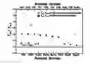


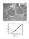
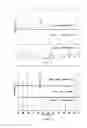
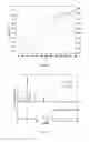
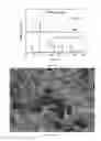
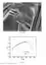
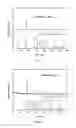
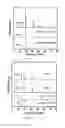
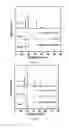
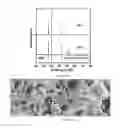
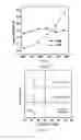
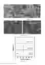
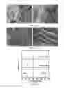
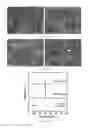
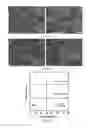
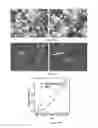
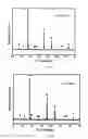
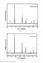
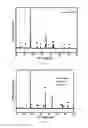
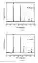
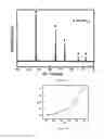
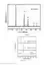
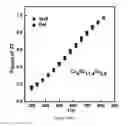
Sources:
- United States Patent and Trademark Office - verify current appl. status at the USPTO↗
Similar patent applications:
- » 20200139440
Thermoelectric materials synthesized by self-propagating high temperature synthesis process and methods thereof - » 20200171571
Thermoelectric materials synthesized by self-propagating high temperature synthesis process and methods thereof - » 20200171570
Thermoelectric materials synthesized by self-propagating high temperature synthesis process and methods thereof - » 20200171572
Thermoelectric materials synthesized by self-propagating high temperature synthesis process and methods thereof - » 20200171573
Thermoelectric materials synthesized by self-propagating high temperature synthesis process and methods thereof - » 20200171574
Thermoelectric materials synthesized by self-propagating high temperature synthesis process and methods thereof - » 20200206818
Thermoelectric materials synthesized by self-propagating high temperature synthesis process and methods thereof
Recent applications in this class:
- » 20230211412 2023-07-06
CERAMIC-METAL COMPOSITE WEAR PART - » 20230201923 2023-06-29
Metallic compounds and metallic matrix composites made using compression activated synthesis - » 20210316363 2021-10-14
Method for producing a sintered component and a sintered component - » 20200261980 2020-08-20
METHOD FOR IDENTIFYING AND FORMING VIABLE HIGH ENTROPY ALLOYS VIA ADDITIVE MANUFACTURING - » 20200206818 2020-07-02
Thermoelectric materials synthesized by self-propagating high temperature synthesis process and methods thereof - » 20200171574 2020-06-04
Thermoelectric materials synthesized by self-propagating high temperature synthesis process and methods thereof - » 20200171573 2020-06-04
Thermoelectric materials synthesized by self-propagating high temperature synthesis process and methods thereof - » 20200171572 2020-06-04
Thermoelectric materials synthesized by self-propagating high temperature synthesis process and methods thereof - » 20200171571 2020-06-04
Thermoelectric materials synthesized by self-propagating high temperature synthesis process and methods thereof - » 20200171570 2020-06-04
Thermoelectric materials synthesized by self-propagating high temperature synthesis process and methods thereof
Recent applications for this Assignee:
- » 20240376008 2024-11-14
HYDRAULIC PHOSPHOGYPSUM (PG)-BASED CEMENTITIOUS MATERIAL, AND PREPARATION METHOD AND USE THEREOF - » 20230077176 2023-03-09
Multi-user slice resource allocation method based on competitive game - » 20180071806 2018-03-15
MULTI-STATION CONTINUOUS HOT STAMPING PRODUCTION LINE AND METHOD - » 20180051751 2018-02-22
Manufacturing method of precision machine tool bearing with high precision stability - » 20170080477 2017-03-23
Radial rolling process for ring product that can control strain distribution of ring product - » 20150344984 2015-12-03
Ultrasound-assisting quenching process and device for performing the same - » 20110106360 2011-05-05
Automatic transmission driving system for electric vehicle motor