Electronic module having circuit boards and a plastic sealing ring that can be molded on by injection molding, in particular for a motor vehicle transmission control unit, and method for producing said electronic module
US20160165727A1
2016-06-09
14/908,070
2014-07-24
✅ Patent granted
US 10,721,819 B2
2020-07-21
WO; PCT/EP2014/065872; 20140724
WO; WO2015/014697; 20150205
Peter Dungba Vo | Kaying Kue
Maginot, Moore & Beck LLP
2036-02-25
Abstract:
An electronic module has a first circuit board element, a second circuit board element, and a spacer. Together, the first circuit board element, the second circuit board element, and the spacer enclose a central cavity, in which components attached to the first circuit board element are accommodated. Respective annular circumferential microstructures are provided on a surface of the first circuit board element directed outward and on a surface of the second circuit board element directed outward, adjacent to an outer periphery of the first circuit board element. In this region, a sealing ring is formed, which has a form-closed connection to both the first and the second circuit board element by means of the microstructures of the first and the second circuit board element. The sealing ring can be made of a resistant plastic, which is molded on by injection molding in the liquid state in the region of the outer periphery of the first circuit board element and flows into recesses of the microstructures and, after the curing, forms the form-closed and sealing connection between the two circuit board elements and the sealing ring thereby formed.
Assignee:
- Robert Bosch GMBH 19,123 🇩🇪 Stuttgart, Germany
Applicant:
Interested in similar patents?
Get notified when new applications in this technology area are published.
Classification:
B29C45/14311 » CPC further
Injection moulding, i.e. forcing the required volume of moulding material through a nozzle into a closed mould; Apparatus therefor incorporating preformed parts or layers, e.g. injection moulding around inserts or for coating articles using means for bonding the coating to the articles
B29C45/14467 » CPC further
Injection moulding, i.e. forcing the required volume of moulding material through a nozzle into a closed mould; Apparatus therefor incorporating preformed parts or layers, e.g. injection moulding around inserts or for coating articles Joining articles or parts of a single article
B29C65/542 » CPC further
Joining of preformed parts ; Apparatus therefor using adhesives, i.e. using supplementary joining material; solvent bonding applying the adhesive between pre-assembled parts by injection
H05K1/141 » CPC further
Printed circuits; Details; Structural association of two or more printed circuits One or more single auxiliary printed circuits mounted on a main printed circuit, e.g. modules, adapters
H05K1/141 » CPC further
Printed circuits; Details; Structural association of two or more printed circuits One or more single auxiliary printed circuits mounted on a main printed circuit, e.g. modules, adapters
B29C39/10 » CPC further
Shaping by casting, i.e. introducing the moulding material into a mould or between confining surfaces without significant moulding pressure; Apparatus therefor for making articles of definite length, i.e. discrete articles incorporating preformed parts or layers, e.g. casting around inserts or for coating articles
H05K5/0043 » CPC further
Casings, cabinets or drawers for electric apparatus provided with connectors and printed circuit boards [PCB], e.g. automotive electronic control units comprising a frame housing mating with two lids wherein the PCB is flat mounted on the frame housing
H05K5/0043 » CPC further
Casings, cabinets or drawers for electric apparatus provided with connectors and printed circuit boards [PCB], e.g. automotive electronic control units comprising a frame housing mating with two lids wherein the PCB is flat mounted on the frame housing
H05K5/0082 » CPC further
Casings, cabinets or drawers for electric apparatus provided with connectors and printed circuit boards [PCB], e.g. automotive electronic control units specially adapted for transmission control units, e.g. gearbox controllers
H05K5/0082 » CPC further
Casings, cabinets or drawers for electric apparatus provided with connectors and printed circuit boards [PCB], e.g. automotive electronic control units specially adapted for transmission control units, e.g. gearbox controllers
H05K5/065 » CPC further
Casings, cabinets or drawers for electric apparatus; Hermetically-sealed casings sealed by encapsulation, e.g. waterproof resin forming an integral casing, injection moulding
H05K5/065 » CPC further
Casings, cabinets or drawers for electric apparatus; Hermetically-sealed casings sealed by encapsulation, e.g. waterproof resin forming an integral casing, injection moulding
B29C66/0246 » CPC further
General aspects of processes or apparatus for joining preformed parts; General aspects dealing with the joint area or with the area to be joined; Preparation of the material, in the area to be joined, prior to joining or welding; Thermal pre-treatments Cutting or perforating, e.g. burning away by using a laser or using hot air
B29C66/02245 » CPC further
General aspects of processes or apparatus for joining preformed parts; General aspects dealing with the joint area or with the area to be joined; Preparation of the material, in the area to be joined, prior to joining or welding; Mechanical pre-treatments, e.g. reshaping with removal of material Abrading, e.g. grinding, sanding, sandblasting or scraping
B29C66/112 » CPC further
General aspects of processes or apparatus for joining preformed parts; General aspects dealing with the joint area or with the area to be joined; Particular design of joint configurations particular design of the joint cross-sections; Joint cross-sections comprising a single joint-segment, i.e. one of the parts to be joined comprising a single joint-segment in the joint cross-section Single lapped joints
B29C66/114 » CPC further
General aspects of processes or apparatus for joining preformed parts; General aspects dealing with the joint area or with the area to be joined; Particular design of joint configurations particular design of the joint cross-sections; Joint cross-sections comprising a single joint-segment, i.e. one of the parts to be joined comprising a single joint-segment in the joint cross-section Single butt joints
B29C66/30322 » CPC further
General aspects of processes or apparatus for joining preformed parts; General aspects dealing with the joint area or with the area to be joined; Particular design of joint configurations the joint involving an anchoring effect making use of protusions or cavities belonging to at least one of the parts to be joined making use of protusions belonging to at least one of the parts to be joined in the form of rugosity
B29C66/71 » CPC further
General aspects of processes or apparatus for joining preformed parts characterised by the composition, physical properties or the structure of the material of the parts to be joined; Joining with non-plastics material characterised by the composition of the plastics material of the parts to be joined
B29C66/7394 » CPC further
General aspects of processes or apparatus for joining preformed parts characterised by the composition, physical properties or the structure of the material of the parts to be joined; Joining with non-plastics material characterised by the intensive physical properties of the material of the parts to be joined, by the optical properties of the material of the parts to be joined, by the extensive physical properties of the parts to be joined, by the state of the material of the parts to be joined or by the material of the parts to be joined being a thermoplastic or a thermoset characterised by the material of the parts to be joined being a thermoplastic or a thermoset characterised by the material of at least one of the parts being a thermoset
B29C66/73161 » CPC further
General aspects of processes or apparatus for joining preformed parts characterised by the composition, physical properties or the structure of the material of the parts to be joined; Joining with non-plastics material characterised by the intensive physical properties of the material of the parts to be joined, by the optical properties of the material of the parts to be joined, by the extensive physical properties of the parts to be joined, by the state of the material of the parts to be joined or by the material of the parts to be joined being a thermoplastic or a thermoset characterised by the intensive physical properties of the material of the parts to be joined; Surface properties Roughness or rugosity
B29C66/73941 » CPC further
General aspects of processes or apparatus for joining preformed parts characterised by the composition, physical properties or the structure of the material of the parts to be joined; Joining with non-plastics material characterised by the intensive physical properties of the material of the parts to be joined, by the optical properties of the material of the parts to be joined, by the extensive physical properties of the parts to be joined, by the state of the material of the parts to be joined or by the material of the parts to be joined being a thermoplastic or a thermoset characterised by the material of the parts to be joined being a thermoplastic or a thermoset characterised by the material of at least one of the parts being a thermoset characterised by the materials of both parts being thermosets
B29L2031/3481 » CPC further
Other particular articles; Electrical apparatus, e.g. sparking plugs or parts thereof Housings or casings incorporating or embedding electric or electronic elements
H05K3/284 » CPC further
Apparatus or processes for manufacturing printed circuits; Secondary treatment of printed circuits; Applying non-metallic protective coatings for encapsulating mounted components
H05K3/284 » CPC further
Apparatus or processes for manufacturing printed circuits; Secondary treatment of printed circuits; Applying non-metallic protective coatings for encapsulating mounted components
H05K2201/042 » CPC further
Indexing scheme relating to printed circuits covered by; Assemblies of printed circuits Stacked spaced PCBs; Planar parts of folded flexible circuits having mounted components in between or spaced from each other
H05K2201/042 » CPC further
Indexing scheme relating to printed circuits covered by; Assemblies of printed circuits Stacked spaced PCBs; Planar parts of folded flexible circuits having mounted components in between or spaced from each other
H05K2201/09063 » CPC further
Indexing scheme relating to printed circuits covered by; Shape and layout; Substrate related Holes or slots in insulating substrate not used for electrical connections
H05K2201/09063 » CPC further
Indexing scheme relating to printed circuits covered by; Shape and layout; Substrate related Holes or slots in insulating substrate not used for electrical connections
H05K2201/1059 » CPC further
Indexing scheme relating to printed circuits covered by; Details of components or other objects attached to or integrated in a printed circuit board; Details of mounted components Connections made by press-fit insertion
H05K2201/1059 » CPC further
Indexing scheme relating to printed circuits covered by; Details of components or other objects attached to or integrated in a printed circuit board; Details of mounted components Connections made by press-fit insertion
H05K2201/10295 » CPC further
Indexing scheme relating to printed circuits covered by; Details of components or other objects attached to or integrated in a printed circuit board; Other objects, e.g. metallic pieces Metallic connector elements partly mounted in a hole of the PCB
H05K2201/10295 » CPC further
Indexing scheme relating to printed circuits covered by; Details of components or other objects attached to or integrated in a printed circuit board; Other objects, e.g. metallic pieces Metallic connector elements partly mounted in a hole of the PCB
H05K2201/2018 » CPC further
Indexing scheme relating to printed circuits covered by; Details of printed circuits not provided for in - Presence of a frame in a printed circuit or printed circuit assembly
H05K2201/2018 » CPC further
Indexing scheme relating to printed circuits covered by; Details of printed circuits not provided for in - Presence of a frame in a printed circuit or printed circuit assembly
H05K2201/2072 » CPC further
Indexing scheme relating to printed circuits covered by; Details of printed circuits not provided for in - Anchoring, i.e. one structure gripping into another
H05K2201/2072 » CPC further
Indexing scheme relating to printed circuits covered by; Details of printed circuits not provided for in - Anchoring, i.e. one structure gripping into another
H05K2203/1327 » CPC further
Indexing scheme relating to apparatus or processes for manufacturing printed circuits covered by; Moulding and encapsulation; Deposition techniques; Protective layers; Moulding and encapsulation Moulding over PCB locally or completely
H05K2203/1327 » CPC further
Indexing scheme relating to apparatus or processes for manufacturing printed circuits covered by; Moulding and encapsulation; Deposition techniques; Protective layers; Moulding and encapsulation Moulding over PCB locally or completely
H05K3/30 IPC
Apparatus or processes for manufacturing printed circuits Assembling printed circuits with electric components, e.g. with resistor
H05K3/30 IPC
Apparatus or processes for manufacturing printed circuits Assembling printed circuits with electric components, e.g. with resistor
H05K3/28 IPC
Apparatus or processes for manufacturing printed circuits; Secondary treatment of printed circuits Applying non-metallic protective coatings
H05K3/28 IPC
Apparatus or processes for manufacturing printed circuits; Secondary treatment of printed circuits Applying non-metallic protective coatings
H05K5/06 IPC
Casings, cabinets or drawers for electric apparatus Hermetically-sealed casings
H05K5/06 IPC
Casings, cabinets or drawers for electric apparatus Hermetically-sealed casings
B29C45/14 IPC
Injection moulding, i.e. forcing the required volume of moulding material through a nozzle into a closed mould; Apparatus therefor incorporating preformed parts or layers, e.g. injection moulding around inserts or for coating articles
H05K5/00 IPC
Casings, cabinets or drawers for electric apparatus
H05K5/00 IPC
Casings, cabinets or drawers for electric apparatus
B29C65/54 IPC
Joining of preformed parts ; Apparatus therefor using adhesives, i.e. using supplementary joining material; solvent bonding applying the adhesive between pre-assembled parts
B29C65/00 IPC
Joining of preformed parts ; Apparatus therefor
B29C65/70 » CPC further
Joining of preformed parts ; Apparatus therefor by moulding
H05K3/00 IPC
Apparatus or processes for manufacturing printed circuits
H05K3/00 IPC
Apparatus or processes for manufacturing printed circuits
H05K3/36 IPC
Apparatus or processes for manufacturing printed circuits Assembling printed circuits with other printed circuits
H05K3/36 IPC
Apparatus or processes for manufacturing printed circuits Assembling printed circuits with other printed circuits
H05K3/368 » CPC further
Apparatus or processes for manufacturing printed circuits; Assembling printed circuits with other printed circuits parallel to each other
H05K3/368 » CPC further
Apparatus or processes for manufacturing printed circuits; Assembling printed circuits with other printed circuits parallel to each other
H05K1/14 IPC
Printed circuits; Details Structural association of two or more printed circuits
H05K1/14 IPC
Printed circuits; Details Structural association of two or more printed circuits
H05K1/144 » CPC main
Printed circuits; Details; Structural association of two or more printed circuits Stacked arrangements of planar printed circuit boards
H05K1/144 » CPC main
Printed circuits; Details; Structural association of two or more printed circuits Stacked arrangements of planar printed circuit boards
H05K3/0044 » CPC further
Apparatus or processes for manufacturing printed circuits; Working of insulating substrates or insulating layers Mechanical working of the substrate, e.g. drilling or punching
H05K3/0044 » CPC further
Apparatus or processes for manufacturing printed circuits; Working of insulating substrates or insulating layers Mechanical working of the substrate, e.g. drilling or punching
H05K1/18 » CPC further
Printed circuits Printed circuits structurally associated with non-printed electric components
H05K1/18 » CPC further
Printed circuits Printed circuits structurally associated with non-printed electric components
B29L2031/7172 » CPC further
Other particular articles; Containers; Packaging elements or accessories, Packages Fuel tanks, jerry cans
B29C45/14508 » CPC further
Injection moulding, i.e. forcing the required volume of moulding material through a nozzle into a closed mould; Apparatus therefor incorporating preformed parts or layers, e.g. injection moulding around inserts or for coating articles; Joining articles or parts of a single article Joining juxtaposed sheet-like articles, e.g. for making trim panels
B29L2031/3425 » CPC further
Other particular articles; Electrical apparatus, e.g. sparking plugs or parts thereof Printed circuits
H05K2201/2036 » CPC further
Indexing scheme relating to printed circuits covered by; Details of printed circuits not provided for in - Permanent spacer or stand-off in a printed circuit or printed circuit assembly
H05K2201/2036 » CPC further
Indexing scheme relating to printed circuits covered by; Details of printed circuits not provided for in - Permanent spacer or stand-off in a printed circuit or printed circuit assembly
H05K2203/1147 » CPC further
Indexing scheme relating to apparatus or processes for manufacturing printed circuits covered by; Treatments characterised by their effect, e.g. heating, cooling, roughening Sealing or impregnating, e.g. of pores
H05K2203/1147 » CPC further
Indexing scheme relating to apparatus or processes for manufacturing printed circuits covered by; Treatments characterised by their effect, e.g. heating, cooling, roughening Sealing or impregnating, e.g. of pores
Description
Electronic module having circuit boards and a plastic sealing ring that can be molded on by injection molding, in particular for a motor vehicle transmission control unit, and method for producing said electronic module
FIELD OF THE INVENTION
The present invention relates to an electronic module, such as may be used in particular for a motor vehicle transmission control unit. The invention furthermore relates to a method for producing such an electronic module.
PRIOR ART
Control devices, for example transmission control units (TCUs), engine control devices, battery control devices, etc. in a motor vehicle, which contain electronic components, should generally be protected in a hermetically sealed fashion against surrounding media. In the case of applications in motor vehicles, such control devices are exposed, for example, to aggressive media such as transmission oil, engine oil, water, urea/water solutions, brake fluid, etc. Added to this, particularly when used in motor vehicles, control devices may be exposed to further potentially damaging effects, for example large temperature variations, mechanical vibration loading, etc.
In order to be able to protect the electronic components of motor vehicle control devices from damaging effects, in particular due to surrounding media, they have in the past usually been contained in elaborately configured hermetically sealed housings. The housings in this case usually consist of sheet metal, in which case, for example, electrical leads to be fed through a housing wall need to be elaborately electrically insulated. Outlay for production of the housing and for the electrical insulation of the leads may be significant.
Simpler, more economical technical solutions have so far often not proven reliable in the long term. For example, it has been observed that seals in the form of elastomer rings, which have been used for hermetically sealing complementary parts of a plastic housing, cannot withstand the robust ambient conditions occurring in motor vehicle applications, in particular the aggressive surrounding media, in the long term, for example for more than ten years. In order to additionally protect the electronic components contained in the housing from media possibly entering, they are often enclosed with a protective gel, although this entails additional outlay and costs.
Alternative solutions, in which a plastic is molded around a so-called lead frame, require for example expensive injection-molding tools.
DE 10 2004 021 931 A1 describes a housing for an electronic circuit.
DISCLOSURE OF THE INVENTION
With embodiments of the present invention, an electronic module and a method for producing such an electronic module are described, with the aid of which simple and economical producibility can be combined with long and reliable durability of electronic modules, in particular for motor vehicle construction. In particular, an advantageous electronic module and a method for its production are described, with which electronic components that are contained in the electronic module are reliably protected in the long term in a hermetically sealed fashion from aggressive surrounding media.
According to a first aspect of the present invention, an electronic module is provided, which has a first and a second circuit board element as well as a spacer. The first circuit board element is provided with at least one electronic component arranged thereon, for example an electronic control circuit. The second circuit board element is provided with at least one electrical component arranged thereon, for example a jack connection, a sensor, etc. The first circuit board element, the second circuit board element and the spacer are configured in a complimentary fashion to one another, in such a way that together they fully enclose a central cavity in which the electronic component of the first circuit board element is received. The electronic module is distinguished in that microstructuring in each case extending around in the shape of a ring is formed both on an outwardly directed surface of the first circuit board element, on an outer circumference of the first circuit board element, and on an outwardly directed surface of the second circuit board element, next to the outer circumference of the first circuit board element. Furthermore, a sealing ring, which is both connected with a form fit to the microstructuring formed on the first circuit board element and is connected with a form fit to the microstructuring formed on the second circuit board element, is formed along the outer circumference of the first circuit board element.
According to a second aspect of the present invention, a method for producing an electronic module is described, in particular an electronic module according to the first aspect of the present invention above. In this case, the first and the second circuit board element as well as the spacer are first provided. Then, microstructuring extending around in the shape of a ring is formed both on an outwardly directed surface of the first circuit board element, on an outer circumference of the first circuit board element, and on an outwardly directed surface of the second circuit board element, next to the outer circumference of the first circuit board element. Subsequently, at least one electronic component is arranged on a surface of the first circuit board element facing toward the central cavity, which is enclosed by the two circuit board elements and the spacer. A sealing ring is then formed along the outer circumference of the first circuit board element, such that the sealing ring is both connected with a form fit to the microstructuring formed on the first circuit board element and is connected with a form fit to the microstructuring formed on the second circuit board element.
Ideas for embodiments of the present invention may, inter alia, be regarded as based on the concepts and discoveries described below.
Previous technical solutions for hermetically sealed encapsulation of electronic components in an electronic module with the aid of a separately provided housing have been recognized to be cost-intensive and elaborate in terms of production. Injection molding around, for example, lead frames provided with electronic components by means of plastic injection molding is also cost-intensive because of the expensive injection molding tools required therefor. Technically simpler solutions with housing parts consisting e.g. of plastic and conventional sealing rings arranged between such housing parts do not seem capable of sealing reliably in the long term, so that protection of the electronic components by additional measures, for example filling regions around the components with a chemically resistant gel, seem necessary.
It has now been discovered that an electronic module can be formed with the aid of two circuit board elements, for example printed circuit boards (PCBs), preferably arranged parallel next to one another. The two circuit board elements are separated from one another by a spacer arranged between them. Together with the spacer, the two circuit board elements enclose a central cavity in which electronic components, for example a transmission control unit, can be received. In order to be able to reliably hermetically seal a region between the two circuit board elements, i.e. adjacent to the spacer, a sealing ring is formed in this region.
In this case, account is taken of the fact that thermosetting materials typically used for circuit board elements, for example epoxides, generally cannot be connected, or can be connected at best poorly, to other materials with the aid of adhesives or the like. Instead of a merely adhesively bonding force-fit connection, it is therefore proposed to form a form-fit connection between the sealing ring and both the first and the second circuit board element. In order to be able to form such a form-fit connection, on the one hand microstructuring is formed on an outwardly directed surface of the first circuit board element, in a region adjacent to its outer circumference. On the other hand, microstructuring is also formed on the second circuit board element on an outwardly directed surface.
Such microstructuring may in this case be understood as a three-dimensional structure with, for example, at least in part outwardly open cavities, indentations and/or undercuts with structure sizes in the nanometer range, for example structure sizes in the range from 10 to 100 nanometers.
The sealing ring may be configured in such a way that at least near-surface regions of the sealing ring engage in the microstructuring on the first or second circuit board element, so as to produce the desired form-fit connection between the sealing ring and these circuit board elements. Such a connection, configured not only with a force fit but also with a form fit, between the sealing ring on the one hand and the two circuit board elements on the other hand can ensure that the sealing ring reliably fixes the cover element on the circuit board element in the long term and an interface between the two elements can be hermetically sealed.
The sealing ring may be formed by molding or injection molding a plastic material onto the surfaces, provided with the microstructuring, of the circuit board elements. During the production of the electronic module, the sealing ring may in this case be formed by molding or injection molding on an initially liquid plastic material, which can flow into the cavities or undercuts of the microstructurings and can subsequently cure. In this way, the desired form-fit connection can be produced in a simple way.
For example, the sealing ring may be made of a plastic, for example thermoplastics (such as polyamide, PA 6, PA 66), thermosets (for example epoxy resins filled with silicon dioxide), etc., an encapsulation compound, for example silicone or epoxy resin compounds, etc., and/or an adhesive, for example based on epoxide. In particular, a plastic which can be processed in liquid form and can then be cured may be used for the sealing ring. Such materials are on the one hand relatively easy to process and economical, but on the other hand they may lead to a long-term hermetic seal as well as sufficient resistance to aggressive media.
The sealing ring may be formed by various methods. For example, the sealing ring may be formed by thermoplastic injection molding, i.e. by injection-molding on a thermoplastic plastic. As an alternative, the sealing ring may be formed by thermoset molding, i.e. by molding on a thermosetting plastic, for example without pressure or with pressure, as for example in the case of transfer molding. As further alternatives, an encapsulation compound may be introduced into an intermediate space provided therefor between the circuit board element and the cover element, and subsequently cured. Adhesive bonding of the circuit board element to the cover element by means of a suitable adhesive, which may for example be based on silicone, epoxy resin, PUR/EP, or the like, may also be envisioned.
The circuit board elements may be configured as commercially available circuit boards, for example consisting of thermosetting plastic, for example glass fiber-reinforced epoxy resin. Such thermosetting materials are often used as a carrier material for circuit boards and may, in particular, have advantageous properties which make them seem suitable for use in electronic modules for motor vehicles. In particular, thermosetting plastics may be chemically stable and resistant to aggressive media and withstand high temperatures as well as large temperature variations.
The spacer may likewise consist of plastic, for example thermoplastic, thermoset or the like. It may be formed as a simple injection-molded part. The spacer has an annular configuration so that it can enclose the intermediate space formed between the two circuit board elements to be separated, at the edges of this intermediate space, so as to fully encapsulate the central cavity intended to receive the electronic components.
The microstructuring intended to achieve the desired form-fit connection with the sealing ring to the two circuit board elements may be formed by various methods.
For example, microstructuring may be formed by laser structuring techniques. In this case, a laser beam is directed onto the surfaces to be structured. By absorption thereof, the material present there can be heated strongly and ultimately vaporized at least locally. By suitable local irradiation of the surfaces to be structured, the desired indentations, cavities and/or undercuts for the microstructuring can therefore be formed. For the laser structuring, low-power lasers with a laser power of up to 100 watts may for example be used, such as are also used as marking lasers, but also ultrashort-pulse lasers.
As an alternative, the microstructuring may also be produced by chemical roughening, mechanical roughening and/or plasma roughening, that is to say by exposing the to be structured to a high-energy plasma. To this end, a commercially available plasma cleaning system may be used, which operates for example with water, hydrogen, oxygen, hydrogen peroxide or ambient air.
In the proposed electronic module, it may in particular be advantageous to configure the sealing ring in such a way that it is exposed outward. Such an outwardly exposed sealing ring may, after the two circuit board elements and the spacer have been correspondingly arranged, be molded on simply from the outside, for example injection-molded on. The microstructurings on the circuit board elements are in this case also outwardly exposed before the sealing ring is formed, i.e. they are arranged outside the central cavity.
According to one embodiment the first circuit board element may have first electrical terminals, which are electrically connected to the at least one electronic component, and the second circuit board element may have second electrical terminals, which are electrically connected to the at least one electrical component. The first electrical terminals may in this case be electrically connected to the second electrical terminals via lines. In this way, the electronic components provided on the first circuit board element can be interconnected with the electrical components provided on the second circuit board element.
In particular, the first electrical terminals may be electrically connected to the second electrical terminals inside the central cavity by means of press-fit connections and/or spring contacts. The press-fit connections or spring contacts used as a connecting electrical line are therefore protected against attack by aggressive surrounding media.
As an alternative, the first electrical terminals may be electrically connected to the second electrical terminals outside the central cavity by means of electrical lines, which extend through the sealing ring. The lines may in this case be arranged between the first and the second circuit board element in the vicinity of the circumference of the first circuit board element, before the sealing ring is formed, for example by injection molding around this region. During the subsequent injection molding, the lines are then embedded in the still liquid material of the sealing ring.
It may be advantageous to equip one or both circuit board elements and/or the spacer with a metal layer as a diffusion barrier. It has been observed that the plastics which may be used for the circuit board elements or the spacer are not always fully leaktight in relation to aggressive media. In particular, some media can defuse through such plastics. An additional metal layer, produced for example by depositing metal on an inner or outer surface of the respective element, can prevent such diffusion through, and therefore improve a hermetic seal.
It is to be pointed out that possible features and advantages of embodiments of the invention are described sometimes in relation to an electronic module according to the invention, sometimes in relation to a transmission control unit according to the invention, and sometimes in relation to a method for producing an electronic module. A person skilled in the art will understand that the described features may be interchanged or combined in a suitable way, and in particular may be transferred from the electronic module in a similar way to the production method, or vice versa, so as to be able to obtain further embodiments, and possibly synergy effects.
BRIEF DESCRIPTION OF THE DRAWINGS
Embodiments of the present invention will be described below with reference to the appended drawings; neither the description nor the drawings are to be interpreted as restricting the invention.
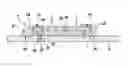
FIGS. 1 (a), (b) illustrate a method for producing an electronic module and a finished electronic module according to one embodiment of the present invention.
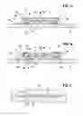
FIG. 2 illustrates in cross section a form-fit connection with the aid of microstructuring.
FIGS. 3 (a), (b) illustrate a method for producing an electronic module and a finished electronic module according to an alternative embodiment of the present invention.
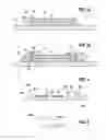
FIG. 4 illustrates an electronic module in a transmission control unit according to one embodiment of the present invention.
FIG. 5 illustrates a transmission having a transmission control unit.
The figures are merely schematic and not true to scale. References which are the same relate to features which are the same or have the same effect in the various figures.
Embodiments of the Invention
An embodiment of an electronic module 1 according to the invention and of a method for the production thereof will be described with reference to FIGS. 1 (a) and (b).
First, a first circuit board element 3 and a second circuit board element 5, as well as a spacer 7, are provided. The two circuit board elements 3, 5 consist of a thermosetting plastic, for example glass fiber-reinforced epoxy resin. The spacer 7 is arranged as a frame between the two circuit board elements 3, 5, which are arranged parallel to one another, so that the circuit board elements 3, 5 together with the annular spacer 7 fully enclose a central cavity 9. The spacer 7 is in this case dimensioned in relation to its thickness in such a way that the central cavity 9 offers sufficient space for electronic components 11, which are arranged on the first circuit board element 3 on a surface facing toward the central cavity 9.
On an outwardly directed surface 13 of the first circuit board element 3, in the vicinity of the outer circumference 15 of this first circuit board element 3, microstructuring 17 is then formed, for example by laser texturing. Microstructuring 21 is also formed on an adjacent surface 19 of the second circuit board element 5. As represented in FIG. 2, the microstructurings 17, 21 comprise a multiplicity of microscopically small indentations 23 in the form of cavities or undercuts. These indentations generally have dimensions in the submicrometer range, and have for example a depth and/or width of between 10 and 500 nm.
The microstructurings 17, 21 provided on the circuit board elements 3, 5 can subsequently assist with hermetically sealed encapsulation of the two circuit board elements 3, 5 with one another. To this end, a plastic in the form of a subsequently curable liquid is applied, for example by injection molding, in the region of the outer circumference 15 of the first circuit board element 3, while extending around this circumference 15 in a ring. The liquid plastic flows at least partially into the indentations 23 of the microstructurings 17, 21. The spacer 7 in this case prevents the liquid plastic from flowing into the central cavity 9. After curing of the plastic, it forms the sealing ring 25. The plastic which has flowed into the indentations 23 and then been cured in this case forms a hermetically sealed form-fit connection between the sealing ring 25 and the respective surfaces 13, 19 of the first and second circuit board elements 3, 5.
In FIG. 1(b), the sealing ring 25 is formed on the left-hand side in the shape of an injection-molded “caterpillar”. The plastic applied in the liquid state merges onto the surfaces 13, 19 of the circuit board elements 3, 5 and flows into the microstructurings 17, 21. A shape of an outwardly exposed surface 27 is, however, formed randomly. On the right-hand side in FIG. 1(b), the sealing ring 25 has been applied with the aid of a tool, with the aid of which a cavity was initially formed adjacent to the surfaces 13, 19 to be connected, which was then filled with the liquid plastic for the sealing ring 25, the plastic subsequently having been cured so that a predeterminable external geometry can be produced for the sealing ring 25.
The electronic components 11 provided on the first circuit board element 3 are connected to first electrical terminals 29. On the second circuit board element 3, second electrical terminals 31 are provided, to which the electrical components 47 (not represented in FIG. 1, but see FIG. 4) provided on this second component 5 are electrically connected. By means of press-fit connections 33 or by means of spring contacts, the first electrical terminals 29 are electrically connected to the second electrical terminals 31. In this way, the electronic components 11 provided in the central cavity 9 can be electrically connected electrically to the electrical components 47 provided outside this central cavity 9.
In order to be able to dissipate heat given off during operation of the electronic components 11 better, the central cavity 9 may finally be filled with a thermally conductive gel 49 through an opening 35. The two circuit board elements 3, 5 may have thermal vias which conduct the heat from the components 11 to outer sides of the two circuit board elements 3, 5.
The filling opening 35 as well as a ventilation opening 37 in the two circuit board elements 3, 5 may finally be closed in a leaktight fashion, for example by a solder, adhesive or a pressed-in pin or a pressed-in ball 39.
FIGS. 3(a) and 3(b) represent an alternative embodiment of an electronic module 1. In this embodiment, electrical connection between the electronic components 11 provided on the first circuit board element 3 and the electrical components 47 provided on the second circuit board element 5 is not carried out inside the central cavity 9. Instead, such an electrical connection between externally lying electrical terminals 41 on the first circuit board element 3 and likewise externally lying terminals 43 on the second circuit board element 5 is carried out via electrical lines 45. These electrical lines 45 may, for example, be provided in the form of a bonding wire, a ribbon cable or an SMD jumper. The electrical lines 45 may in this case be arranged close to the circumference of the first circuit board element 3 and subsequently be jointly encapsulated during the injection molding of liquid plastic around this circumference 15 in order to form the sealing ring 25. Such externally lying electrical lines 45, particularly in the form of bonds, may have the advantage over the press contacts represented in FIG. 1 that they function without bores in the circuit board elements 3, and therefore allow simpler preparation of the component parts. In the case of bores for press contacts, a through-hole should be avoided so that no external leaks are formed.
FIG. 4 illustrates a transmission control unit 100 having a plurality of electronic modules 1, an external sensor 101 used as an electrical component 47, and a plurality of jacks 103 likewise used as electrical components 47. The second circuit board element 5 in this case refers to the printed circuit board which undertakes interconnection of the electronics with electrical components 47 of an external circuit. In the transmission control unit 100, these are the sensor 101, the jack 103, further electronics and actuators, etc. The first circuit board element 3 may be a circuit board in the form of an HDI-PCB (high identity interconnect), a DBC (direct bonded copper), or a ceramic substrate (LTCC, HTCC, thick film, etc.), which form for example circuits for electronics of a transmission control unit. Primarily, however, the inventive concept on which the present invention is based may be used in PCB-to-PCB sealing. A carrier plate 105 mechanically supports the electronic module 1.
FIG. 5 shows a vehicle transmission 200 having a transmission control unit 100 formed with the aid of an electronic module according to the invention. The described electronic modules may, however, also be used for other applications, for example in engines or at other places in the vehicle, for example in a fuel tank, cooling water, urea system, electrical drive, in the spray water area, etc.
Claims
1. An electronic module comprising:
a first circuit board element having at least one electronic component arranged thereon;
a second circuit board element having at least one electronic component arranged thereon; and
a spacer,
wherein the first circuit board element, the second circuit board element, and the spacer are configured such that together they fully enclose a central cavity in which the at least one electronic component of the first circuit board element is received;
wherein microstructuring is formed extending in the shape of a ring on an outwardly directed surface of the first circuit board element, is formed extending in the shape of a ring on an outer circumference of the first circuit board element, and is formed extending in the shape of a ring on an outwardly directed surface of the second circuit board element, next to the outer circumference of the first circuit board element, and
wherein a sealing ring is formed along the outer circumference of the first circuit board element, the sealing ring connected with a form fit to the microstructuring formed on the first circuit board element and connected with a form fit to the microstructuring formed on the second circuit board element.
2. The electronic module as claimed in claim 1, wherein the sealing ring is formed by molding a plastic material onto the surfaces, provided with the microstructuring, of the first circuit board element and of the second circuit board element.
3. The electronic module as claimed in claim 1, wherein at least one of the first circuit board element and the second circuit board element consists of a thermosetting plastic.
4. The electronic module as claimed in claim 1, wherein the sealing ring consists of at least one of a plastic, encapsulation compound and a plastic, encapsulation adhesive.
5. The electronic module as claimed in claim 1, wherein the sealing ring is exposed outward.
6. The electronic module as claimed in claim 1, wherein:
the first circuit board element has first electrical terminals, which are electrically connected to the at least one electronic component,
the second circuit board element has second electrical terminals, which are electrically connected to the at least one electrical component, and
the first electrical terminals are electrically connected to the second electrical terminals via lines.
7. The electronic module as claimed in claim 6, wherein the first electrical terminals are electrically connected to the second electrical terminals inside the central cavity by at least one of press-fit connections and spring contacts.
8. The electronic module as claimed in claim 6, wherein the first electrical terminals are electrically connected to the second electrical terminals outside the central cavity by electrical lines, which extend through the sealing ring.
9. A transmission control unit for a motor vehicle, comprising:
an electronic module, including:
a first circuit board element having at least one electronic component arranged thereon;
a second circuit board element having at least one electronic component arranged thereon; and
a spacer,
wherein the first circuit board element, the second circuit board element, and the spacer are configured such that together they fully enclose a central cavity in which the at least one electronic component of the first circuit board element is received;
wherein microstructuring is formed extending in the shape of a ring on an outwardly directed surface of the first circuit board element, is formed extending in the shape of a ring on an outer circumference of the first circuit board element, and is formed extending in the shape of a ring on an outwardly directed surface of the second circuit board element, next to the outer circumference of the first circuit board element, and
wherein a sealing ring is formed along the outer circumference of the first circuit board element, the sealing ring connected with a form fit to the microstructuring formed on the first circuit board element and connected with a form fit to the microstructuring formed on the second circuit board element.
10. A method for producing an electronic module, comprising:
providing a first circuit board element, a second circuit board element, and a spacer, the first circuit board element, the second circuit board element, and the spacer being configured such that together they fully enclose a central cavity in which an electronic component of the first circuit board element is received;
forming microstructuring in the shape of a ring on an outwardly directed surface of the first circuit board element, forming microstructuring in the shape of a ring on an outer circumference of the first circuit board element, and forming microstructuring in the shape of a ring on an outwardly directed surface of the second circuit board element, next to the outer circumference of the first circuit board element;
arranging at least one electronic component on a surface of the first circuit board element facing toward the central cavity; and
forming a sealing ring along the outer circumference of the first circuit board element, such that the sealing ring is connected with a form fit to the microstructuring formed on the first circuit board element and is connected with a form fit to the microstructuring formed on the second circuit board element.
11. The method as claimed in claim 10, wherein forming the microstructuring includes at least one of laser structuring, chemical roughening, mechanical roughening and plasma roughening.
12. The method as claimed in claim 10, wherein forming the sealing ring includes at least one of thermoplastic injection molding, thermoset injection molding, adhesive bonding and filling with an encapsulation compound.
Images & Drawings included:
Sources:
- United States Patent and Trademark Office - verify current appl. status at the USPTO↗
Recent applications in this class:
- » 20250254795 2025-08-07
WIRING SUBSTRATE - » 20250254794 2025-08-07
ELECTRONIC DEVICE - » 20250247959 2025-07-31
SANDWICH STRUCTURE POWER SUPPLY MODULE - » 20250247958 2025-07-31
STACKING BOARDS ON RIGID-FLEXES TO DECOUPLE DYNAMIC BENDS - » 20250240890 2025-07-24
METHOD OF EMBEDDING AN EMBEDDABLE OBJECT INTO A STACKED SUBSTRATE AND STACKED SUBSTRATE ARRANGEMENT - » 20250240889 2025-07-24
SUBSTRATE STRUCTURE AND MANUFACTURING METHOD THEREOF - » 20250212331 2025-06-26
ELECTRONIC DEVICE INCLUDING INTERPOSER - » 20250185168 2025-06-05
CIRCUIT MODULE - » 20250133659 2025-04-24
DEVICE FOR FIXING CAMERA MODULE CIRCUIT BOARD, AND CAMERA MODULE - » 20250126715 2025-04-17
PRINTED CIRCUIT BOARD
Recent applications for this Assignee:
- » 20250154889 2025-05-15
PRESSURE CONTROL IN AN EXHAUST AFTERTREATMENT SYSTEM - » 20250154580 2025-05-15
ENZYME TRANSLOCATORS IN NANOGAP WITH 3' -ESTERS - » 20250147582 2025-05-08
METHOD FOR DETERMINING AN EYE DISTANCE IN A PAIR OF DATA GLASSES, AND DATA GLASSES - » 20250146568 2025-05-08
DRIVE ASSEMBLY AND VEHICLE HAVING SUCH A DRIVE ASSEMBLY - » 20250146495 2025-05-08
Flexible Pump Assembly for Use in a Fan Drive - » 20250140882 2025-05-01
FUEL CELL SYSTEM HAVING ENERGY RECUPERATION - » 20250137810 2025-05-01
METHOD FOR MATCHING A DIGITAL ROAD MAP - » 20250137033 2025-05-01
DNA UNFOLDING USING A FREE-END TAG FLOW MODIFIER - » 20250119751 2025-04-10
A BLUETOOTH COMMUNICATION METHOD AND SYSTEM - » 20250118116 2025-04-10
Diagnostic Protocol Search With Improved Efficiency