Gimbal
US20170264796A1
2017-09-14
15/529,499
2015-12-15
✅ Patent granted
US 10,070,026 B2
2018-09-04
WO; PCT/CN2015/097351; 20151215
WO; WO2016/095792; 20160623
WB Perkey
2035-12-15
Abstract:
A gimbal includes a housing (1). A gyroscope board (4), a camera (21), and a camera main control board (22) electrically connected with the camera are disposed in the housing. A Wi-Fi circuit board (31) and a Wi-Fi antenna (33) are also disposed in the housing. The Wi-Fi circuit board is electrically connected with the camera main control board. The camera is fixed on the housing. The gimbal achieves the independent Wi-Fi transmission, so that the structure is simplified.
Inventors:
- Yu TIAN 10 🇨🇳 Kunshan, Jiangsu, China
- Wenyan Jiang 8 🇨🇳 Kunshan, Jiangsu, China
- Yu TIAN 35 🇨🇳 Jiangsu, China
- Wenyan JIANG 34 🇨🇳 Jiangsu, China
Assignee:
- Yuneec Technology Co., Limited 10 🇨🇳 Hong Kong, China
Applicant:
Interested in similar patents?
Get notified when new applications in this technology area are published.
Classification:
H04N5/2252 » CPC main
Details of television systems; Studio circuitry; Studio devices; Studio equipment ; Cameras comprising an electronic image sensor, e.g. digital cameras, video cameras, TV cameras, video cameras, camcorders, webcams, camera modules for embedding in other devices, e.g. mobile phones, computers or vehicles; Television cameras ; Cameras comprising an electronic image sensor, e.g. digital cameras, video cameras, camcorders, webcams, camera modules specially adapted for being embedded in other devices, e.g. mobile phones, computers or vehicles; Constructional details Housings
H05K1/0203 » CPC further
Printed circuits; Details; Thermal arrangements, e.g. for cooling, heating or preventing overheating Cooling of mounted components
H05K1/0203 » CPC further
Printed circuits; Details; Thermal arrangements, e.g. for cooling, heating or preventing overheating Cooling of mounted components
H05K7/1427 » CPC further
Constructional details common to different types of electric apparatus; Mounting supporting structure in casing or on frame or rack; Printed circuit boards receptacles, e.g. stacked structures, electronic circuit modules or box like frames Housings
H05K7/1427 » CPC further
Constructional details common to different types of electric apparatus; Mounting supporting structure in casing or on frame or rack; Printed circuit boards receptacles, e.g. stacked structures, electronic circuit modules or box like frames Housings
H05K5/0004 » CPC further
Casings, cabinets or drawers for electric apparatus comprising several parts forming a closed casing
H05K5/0004 » CPC further
Casings, cabinets or drawers for electric apparatus comprising several parts forming a closed casing
H05K2201/066 » CPC further
Indexing scheme relating to printed circuits covered by; Thermal details Heatsink mounted on the surface of the PCB
H05K2201/066 » CPC further
Indexing scheme relating to printed circuits covered by; Thermal details Heatsink mounted on the surface of the PCB
B64C39/02 IPC
Aircraft not otherwise provided for characterised by special use
B64C39/024 » CPC further
Aircraft not otherwise provided for characterised by special use of the remote controlled vehicle type, i.e. RPV
B64C2201/127 » CPC further
Unmanned aerial vehicles; Equipment therefor adapted for particular use for photography, or video recording, e.g. by using cameras
G03B17/561 » CPC further
Details of cameras or camera bodies; Accessories therefor; Accessories Support related camera accessories
H04B7/04 » CPC further
Radio transmission systems, i.e. using radiation field; Diversity systems; Multi-antenna system, i.e. transmission or reception using multiple antennas using two or more spaced independent antennas
H04W84/12 » CPC further
Network topologies; Hierarchically pre-organised networks, e.g. paging networks, cellular networks, WLAN [Wireless Local Area Network] or WLL [Wireless Local Loop]; Small scale networks; Flat hierarchical networks WLAN [Wireless Local Area Networks]
H05K2201/10098 » CPC further
Indexing scheme relating to printed circuits covered by; Details of components or other objects attached to or integrated in a printed circuit board; Types of components Components for radio transmission, e.g. radio frequency identification [RFID] tag, printed or non-printed antennas
H04N5/225 IPC
Details of television systems; Studio circuitry; Studio devices; Studio equipment ; Cameras comprising an electronic image sensor, e.g. digital cameras, video cameras, TV cameras, video cameras, camcorders, webcams, camera modules for embedding in other devices, e.g. mobile phones, computers or vehicles Television cameras ; Cameras comprising an electronic image sensor, e.g. digital cameras, video cameras, camcorders, webcams, camera modules specially adapted for being embedded in other devices, e.g. mobile phones, computers or vehicles
B64D47/08 » CPC further
Equipment not otherwise provided for Arrangements of cameras
G03B17/56 IPC
Details of cameras or camera bodies; Accessories therefor Accessories
H05K5/03 » CPC further
Casings, cabinets or drawers for electric apparatus; Details Covers
H05K5/03 » CPC further
Casings, cabinets or drawers for electric apparatus; Details Covers
H05K7/14 IPC
Constructional details common to different types of electric apparatus Mounting supporting structure in casing or on frame or rack
H05K7/14 IPC
Constructional details common to different types of electric apparatus Mounting supporting structure in casing or on frame or rack
H05K1/02 IPC
Printed circuits Details
H05K1/02 IPC
Printed circuits Details
H05K5/00 IPC
Casings, cabinets or drawers for electric apparatus
H05K5/00 IPC
Casings, cabinets or drawers for electric apparatus
Description
CROSS REFERENCE OF RELATED APPLICATION
This is a U.S. National Stage under 35 U.S.C. 371 of the International Application PCT/CN2015/097351, filed Dec. 15, 2015, which claims priority under 35 U.S.C. 119(a-d) to CN201420795952.2, filed Dec. 15, 2014. The full text of the above-mentioned Chinese patent application is included in the present invention.
BACKGROUND OF THE PRESENT INVENTION
Field of Invention
The present invention relates to a gimbal.
Description of Related Arts
With the development of society and industry by leaps and bounds, the UAV (Unmanned Aerial Vehicle) aerial photography has been applied to more and more fields, such as film and television shooting, fire patrol shooting and traffic monitoring. The synchronous transmission of the UAV aerial photography has important significances. However,the gimbal itself now on the market does not include a Wi-Fi (wireless fidelity) digital transmission system, and it is necessary for the gimbal to transmit through an external device. Moreover, the internal structure of the gimbal is complex, electronic components need to be connected with each other through wires, which results in the complex connections among the overall wires, thus it is prone to failure. In addition, because the camera itself rotates, the wires will be driven to move together, thus it is easy to failure due to worn wires.
SUMMARY OF THE PRESENT INVENTION
A technical problem to be resolved of the present invention is to provide a gimbal for overcoming drawbacks that the existing gimbals are unable to independently achieve the Wi-Fi digital transmission, and it is difficult to arrange electronic components due to complex internal wire connections.
The present invention resolves the above technical problem through a technical solution as follows.
A gimbal comprises a housing, wherein: a gyroscope board, a camera and a camera main control board electrically connected with the camera are disposed in the housing; a Wi-Fi (wireless fidelity) circuit board and Wi-Fi antennas are also disposed in the housing; the Wi-Fi circuit board is electrically connected with the camera main control board, the camera is fixed on the housing. While operating, the Wi-Fi circuit board is adapted for receiving video signals and transmitting the video signals to an exterior through the Wi-Fi antennas. The Wi-Fi circuit board always rotates with the housing for saving wires and avoiding wear and tear of the wires.
Preferably, the camera is fixed in the housing through a camera frame; through the camera frame, the camera is able to be firmly fixed in the housing.
Preferably, an amount of the Wi-Fi antennas is two;the two Wi-Fi antennas are respectively located at an upper side and a lower side of the housing for enhancing the signal strength and avoiding shielding of other frame structures while rotating the housing, thereby ensuring the stability of signals.
Preferably, the gimbal further comprises a heat sink which is attached to the Wi-Fi circuit board for effectively dissipating heat of the Wi-Fi circuit board.
Preferably, the housing comprises a front cover and a rear cover connected with the front cover through threaded components.
Preferably, the gimbal further comprises a second shaft arm, wherein: a first motor seat and a first bearing seat are respectively disposed at two sides of the rear cover, a first shaft motor is fixed to the first motor seat, a first bearing is fixed to the first bearing seat, a hollow shaft penetrates through the first bearing, the second shaft arm is respectively connected with the hollow shaft and the first shaft motor, such that the housing is able to rotate relatively to the second shaft arm for adjusting camera angles.
Preferably, the first motor seat and the first bearing seat are respectively covered with two end caps for sealing the housing, so as to avoid components in the housing being eroded.
Preferably, the gimbal further comprises a second shaft motor which is respectively connected with the second shaft arm and a third shaft arm, such that the second shaft arm is able to rotate relatively to the third shaft arm, so as to further drive the housing to rotate.
Preferably, the gimbal further comprises a third shaft seat, wherein the third shaft arm is fixed to the third shaft seat.
Preferably, the gimbal further comprises a third shaft motor which is respectively connected with the third shaft seat and a gimbal shock absorption plate, such that the third shaft seat is able to rotate relatively to the gimbal shock absorption plate, so as to further drive the housing to rotate.
Preferably, the gimbal further comprises gimbal fixed supports, wherein multiple shock absorption balls are disposed between the gimbal shock absorption plate and each of the gimbal fixed supports for reducing the vibration of the gimbal, so as to ensure the image quality of the camera.
Preferably, a gimbal receiver, a photoelectric encoder and a gimbal main control board are disposed in the third shaft seat; the third shaft seat is covered with a stuffy cover for sealing the third shaft seat, so as to ensure the sealing effect.
In the present invention, the above-described preferred conditions can be arbitrarily combined on the basis of common senses in the field to obtain the preferred embodiments of the present invention
The positive effects of the present invention are that:in the present invention, the Wi-Fi circuit board is disposed in the housing, thus realizing the independent Wi-Fi transmission of the gimbal, simplifying the connections among the wires, reducing the failure due to the wear and tear of the wires, and decreasing the failure rate.
BRIEF DESCRIPTION OF THE DRAWINGS
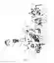
FIG. 1 is an exploded structural diagram of a gimbal according to a preferred embodiment of the present invention.
FIG. 2 is an internally structurally schematic view of a housing according to the above preferred embodiment of the present invention.
FIG. 3 is a top view of the gimbal according to the preferred embodiment of the present invention.
FIG. 4 is a front view of the gimbal according to the preferred embodiment of the present invention.
FIG. 5 is a side view of the gimbal according to the preferred embodiment of the present invention.
Descriptions of drawing reference numbers are as follows.
- 1: housing; 11: front cover; 12: rear cover; 13: end cap; 14: end cap; 21: camera; 22: camera main control board; 23: camera frame; 31: Wi-Fi circuit board; 32: heat sink; 33: Wi-Fi antenna; 34: Wi-Fi antenna; 4: gyroscope board; 51: first shaft motor; 52: second shaft arm; 53: first bearing; 54: hollow shaft; 61: second shaft motor; 621: third shaft arm; 622: decorating component; 631: third shaft seat; 632: stuffy cover; 71: third shaft motor; 721: gimbal fixed support; 722: shock absorption ball; 723: gimbal shock absorption plate; 81: gimbal receiver; 82: fastening component; 83: gimbal main control board; 84: photoelectric encoder; 91: screw; 92: screw; 93: screw; 94: screw; 95: screw; 96: screw; 97: screw; 98: screw; 99: slip ring power wire.
DETAILED DESCRIPTION OF THE PREFERRED EMBODIMENT
The present invention is further more clearly and completely explained with accompanying preferred embodiments and drawings as follows.
As shown in FIGS. 1-5, the present invention provides a gimbal. Specifically, referring to FIGS. 3-5, the gimbal comprises a housing 1 which is capable of rotating around three axes.
Referring to FIGS. 1 and 2, the housing 1 comprises a front cover 11 and a rear cover 12 connected with the front cover 11 through multiple screws 95.
A gyroscope board 4, a camera 21 and a camera main control board 22 electrically connected with the camera 21 are disposed in the housing 1. The camera 21 is installed on the camera frame 23. The camera frame 23 is connected with the rear cover 12 through multiple screws 96 for fastening.
A Wi-Fi (wireless fidelity) circuit board 31, Wi-Fi antennas 33, 34 and a heat sink 32 are also disposed in the housing 1, wherein:the Wi-Fi circuit board 31 is electrically connected with the camera main control board 22;the heat sink 32 is attached to the Wi-Fi circuit board 31 for effectively dissipating heat of the Wi-Fi circuit board 31; both the heat sink 32 and the Wi-Fi circuit board 31 are fixed to the rear cover 12 through screws 93.
While operating, the Wi-Fi circuit board is adapted for receiving video signals and transmitting the video signals to an exterior through the Wi-Fi antennas 33, 34. The Wi-Fi circuit board 31 always rotates with the housing 1, which not only saves wires for connecting the housing 1 with the exterior, but also avoids wear and tear of the wires due to rotating the housing 1.
Preferably, as shown in FIG. 2,the present invention comprises the Wi-Fi antennas 33, 34 which are respectively connected with the Wi-Fi circuit board 31 and located at a lower side and an upper side of the housing 1 for enhancing the signal strength and avoiding shielding of other frame structures while rotating the housing 1, thereby ensuring the stability of signals.
As shown in FIG. 1, a second shaft arm 52 is disposed at an outside of the housing 1, a first motor seat and a first bearing seat are respectively disposed at two sides of the rear cover 12, the second shaft arm 52 is fixed to one end of a first shaft motor 51 through screws 98, the first motor seat is also fixed to the other end of the first shaft motor 51 through screws. The two ends of the first shaft motor 51 are able to produce relatively rotational movements. A first bearing 53 is fixed to the first bearing seat. A hollow shaft 54 penetrates through the first bearing 53.
The second shaft arm 52 is respectively connected with the hollow shaft 54 and the first shaft motor 51, and the two ends of the first shaft motor 51 are able to produce relatively rotational movements, such that the housing 1 is able to rotate relatively to the second shaft arm 52 for adjusting camera angles.
Preferably, the first motor seat and the first bearing seat are respectively covered with end caps 13, 14 for sealing the housing 1, so as to avoid components in the housing being eroded.
The gimbal provided by the present invention further comprises a second shaft motor 61 which is respectively fixed to the second shaft arm 52 through screws 92 and connected with a third shaft arm 621 through screws 91, two ends of the second shaft motor 61 are able to produce relatively rotational movements, such that the second shaft arm 52 is able to rotate relatively to the third shaft arm 621, for further driving the housing 1 to rotate.
The gimbal further comprises a third shaft seat 631, and the third shaft arm 621 is fixed to the third shaft seat 631. A gimbal receiver 81, a photoelectric encoder 84 and a gimbal main control board 83 are disposed in the third shaft seat 631. The gimbal main control board 83 is fixed to the third shaft seat 631 through a fastening component 82. The third shaft seat 631 is covered with a stuffy cover 632 for sealing the third shaft seat 631, so as to ensure the sealing effect.
The gimbal further comprises a third shaft motor 71, one end of which is connected with the third shaft seat 631 and the other end thereof is connected with a gimbal shock absorption plate 723 through screws 97, such that the third shaft seat 631 is able to rotate relatively to the gimbal shock absorption plate 723, so as to further drive the housing 1 to rotate.
The gimbal further comprises four gimbal fixed supports 721, wherein multiples hock absorption balls 722 are disposed between the gimbal shock absorption plate 723 and each of the gimbal fixed supports 721 for reducing the vibration of the gimbal, so as to ensure the image quality of the camera.
Furthermore, a slip ring power wire 99 is disposed on the gimbal shock absorption plate 723 for supplying power. A decorating component 622 is connected with an outside of the third shaft arm 621 through screws 94 for ensuring aesthetics.
While the specific embodiments of the present invention have been described above, it should be understood by one skilled in the art that these embodiments are merely illustrative and that various changes or modifications may be made to these embodiments without departing from the principles and spirit of the present invention.
Accordingly, the protective scope of the present invention is limited by the appended claims.
Claims
1. A gimbal, comprising a housing, wherein: a gyroscope board, a camera and a camera main control board electrically connected with the camera are disposed in the housing; a Wi-Fi (wireless fidelity) circuit board and Wi-Fi antennas are disposed in the housing; the Wi-Fi circuit board is electrically connected with the camera main control board, the camera is fixed on the housing.
2. The gimbal, as recited in claim 1, wherein the camera is fixed in the housing through a camera frame.
3. The gimbal, as recited in claim 1, wherein an amount of the Wi-Fi antennas is two; the two Wi-Fi antennas are respectively located at an upper side and a lower side of the housing.
4. The gimbal, as recited in claim 1, wherein a heat sink is disposed in the housing and is attached to the Wi-Fi circuit board.
5-12. (canceled)
13. The gimbal, as recited in claim 2, wherein a heat sink is disposed in the housing and is attached to the Wi-Fi circuit board.
14. The gimbal, as recited in claim 3, wherein a heat sink is disposed in the housing and is attached to the Wi-Fi circuit board.
15. The gimbal, as recited in claim 13, wherein the housing comprises a front cover and a rear cover connected with the front cover through threaded components.
16. The gimbal, as recited in claim 14, wherein the housing comprises a front cover and a rear cover connected with the front cover through threaded components.
17. The gimbal, as recited in claim 15, further comprising a second shaft arm, wherein a first motor seat and a first bearing seat are respectively disposed at two sides of the rear cover, a first shaft motor is fixed to the first motor seat, a first bearing is fixed to the first bearing seat, a hollow shaft penetrates through the first bearing, the second shaft arm is respectively connected with the hollow shaft and the first shaft motor.
18. The gimbal, as recited in claim 16, further comprising a second shaft arm, wherein a first motor seat and a first bearing seat are respectively disposed at two sides of the rear cover, a first shaft motor is fixed to the first motor seat, a first bearing is fixed to the first bearing seat, a hollow shaft penetrates through the first bearing, the second shaft arm is respectively connected with the hollow shaft and the first shaft motor.
19. The gimbal, as recited in claim 17, wherein the first motor seat and the first bearing seat are respectively covered with two end caps.
20. The gimbal, as recited in claim 18, wherein the first motor seat and the first bearing seat are respectively covered with two end caps.
21. The gimbal, as recited in claim 19, further comprising a second shaft motor which is respectively connected with the second shaft arm and a third shaft arm.
22. The gimbal, as recited in claim 20, further comprising a second shaft motor which is respectively connected with the second shaft arm and a third shaft arm.
23. The gimbal, as recited in claim 21, further comprising a third shaft seat, wherein the third shaft arm is fixed to the third shaft seat.
24. The gimbal, as recited in claim 22, further comprising a third shaft seat, wherein the third shaft arm is fixed to the third shaft seat.
25. The gimbal, as recited in claim 23, further comprising a third shaft motor which is respectively connected with the third shaft seat and a gimbal shock absorption plate.
26. The gimbal, as recited in claim 24, further comprising a third shaft motor which is respectively connected with the third shaft seat and a gimbal shock absorption plate.
27. The gimbal, as recited in claim 26, further comprising gimbal fixed supports, wherein multiple shock absorption balls are disposed between the gimbal shock absorption plate and each of the gimbal fixed supports.
28. The gimbal, as recited in claim 27, wherein a gimbal receiver, a photoelectric encoder and a gimbal main control board are disposed in the third shaft seat, the third shaft seat is covered with a stuffy cover.
Images & Drawings included:


Sources:
- United States Patent and Trademark Office - verify current appl. status at the USPTO↗
Similar patent applications:
- » 20190064637
Gimbal control method, gimbal control apparatus, and gimbal - » 20200130861
Gimbal rotation method, gimbal, aircraft, and method and system for controlling rotation of gimbal - » 20170301230
Gimbal remote controller and handheld gimbal using the gimbal remote controller - » 20180146126
Gimbal control method, gimbal control system and gimbal device - » 20190339591
Gimbal control method, gimbal control apparatus, and gimbal - » 10705885
Precise positioning actuator for head element, head gimbal assembly with the actuator, disk drive apparatus with the head gimbal assembly and manufacturing method of head gimbal assembly - » 20050264934
Thin-film magnetic head, head gimbal assembly with thin-film magnetic head, head arm assembly with head gimbal assembly, magnetic disk drive apparatus with head gimbal assembly and manufacturing method of thin-film magnetic head - » 20090059431
SUSPENSION, HEAD GIMBALS ASSEMBLY, METHOD FOR MANUFACTURING HEAD GIMBALS ASSEMBLY, STORAGE APPARATUS, AND APPARATUS FOR MANUFACTURING HEAD GIMBALS ASSEMBLY - » 10235586
Head gimbal assembly with precise positioning actuator for head element, disk drive apparatus with the head gimbal assembly, and manufacturing method of the head gimbal assembly - » 20200213518
METHOD FOR CONTROLLING GIMBAL, GIMBAL CONTROLLER, AND GIMBAL
Recent applications in this class:
- » 20240129607 2024-04-18
Camera housing structure for enhanced manufacture assembly and repair - » 20240098348 2024-03-21
Camera module on flexible interconnect tape - » 20230403447 2023-12-14
SHARED WINDOW FOR COMPUTING DEVICE CAMERA LENSES AND PHOTOFLASH - » 20230269449 2023-08-24
Retractable camera module and electronic device - » 20230217089 2023-07-06
Protective lens cover for a camera - » 20230188815 2023-06-15
Camera with dock having automated alignment - » 20230168500 2023-06-01
SMART GLASSES AND CAMERA DEVICE THEREOF - » 20230156306 2023-05-18
Imaging apparatus - » 20230142061 2023-05-11
Camera device - » 20230132784 2023-05-04
Thermally stable sawmill scanner
Recent applications for this Assignee:
- » 20190101912 2019-04-04
Remote control apparatus and remote control system - » 20180155016 2018-06-07
Aerial vehicle - » 20180149479 2018-05-31
Geo-location or navigation camera, and aircraft and navigation method therefor - » 20180136650 2018-05-17
Aircraft and obstacle avoidance method and system thereof - » 20180047296 2018-02-15
Fixed-wing aircraft and flight control method and system thereof - » 20180046200 2018-02-15
Aircraft and roll method thereof - » 20180033294 2018-02-01
Remote control device for aircraft, aircraft system and remote control method for aircraft system - » 20180023752 2018-01-25
Gimbal handheld holder - » 20170305574 2017-10-26
Aircraft system