Adaptive dynamic model for automated vehicle
US20210247772A1
2021-08-12
17/241,002
2021-04-26
✅ Patent granted
US 11,774,974 B2
2023-10-03
-
-
Hussein Elchanti
Fish & Richardson P.C.
2041-04-26
Abstract:
An operating system for an automated vehicle includes a failure-detector and a controller. The failure-detector detects a component-failure on a host-vehicle. Examples of the component-failure include a flat-tire and engine trouble that reduces engine-power. The controller operates the host-vehicle based on a dynamic-model. The dynamic-model is varied based on the component-failure detected by the failure-detector.
Inventors:
- Junqing Wei 47 🇺🇸 Bridgeville, PA, United States
- Jarrod M. Snider 14 🇺🇸 Pittsburgh, PA, United States
- Ludong Sun 16 🇺🇸 Pittsburgh, PA, United States
- Zachary Thomas Batts 8 🇺🇸 Pittsburgh, PA, United States
- Junsung Kim 2 🇺🇸 Austin, TX, United States
Assignee:
- MOTIONAL AD LLC 298 🇺🇸 Boston, MA, United States
Applicant:
Interested in similar patents?
Get notified when new applications in this technology area are published.
Classification:
G05D1/0214 » CPC main
Control of position, course or altitude of land, water, air, or space vehicles, e.g. automatic pilot; Control of position or course in two dimensions specially adapted to land vehicles with means for defining a desired trajectory in accordance with safety or protection criteria, e.g. avoiding hazardous areas
B60C23/0408 » CPC further
Devices for measuring, signalling, controlling, or distributing tyre pressure or temperature, specially adapted for mounting on vehicles; Arrangement of tyre inflating devices on vehicles, e.g. of pumps or of tanks; Tyre cooling arrangements; Signalling devices actuated by tyre pressure mounted on the wheel or tyre transmitting the signals by non-mechanical means from the wheel or tyre to a vehicle body mounted receiver
B62D15/021 » CPC further
Steering not otherwise provided for; Steering position indicators ; Steering position determination; Steering aids Determination of steering angle
B62D15/025 » CPC further
Steering not otherwise provided for; Steering position indicators ; Steering position determination; Steering aids Active steering aids, e.g. helping the driver by actively influencing the steering system after environment evaluation
G01L5/221 » CPC further
Apparatus for, or methods of, measuring force, work, mechanical power, or torque, specially adapted for specific purposes for measuring the force applied to control members, e.g. control members of vehicles, triggers to steering wheels, e.g. for power assisted steering
G05D1/0072 » CPC further
Control of position, course or altitude of land, water, air, or space vehicles, e.g. automatic pilot with safety arrangements to counteract a motor failure
G07C5/0808 » CPC further
Registering or indicating the working of vehicles; Registering or indicating performance data other than driving, working, idle, or waiting time, with or without registering driving, working, idle or waiting time Diagnosing performance data
B60W2510/18 » CPC further
Input parameters relating to a particular sub-units Braking system
B60W2510/202 » CPC further
Input parameters relating to a particular sub-units; Steering systems Steering torque
B60W2520/10 » CPC further
Input parameters relating to overall vehicle dynamics Longitudinal speed
B60W2520/28 » CPC further
Input parameters relating to overall vehicle dynamics Wheel speed
B60W2530/20 » CPC further
Input parameters relating to vehicle conditions or values, not covered by groups or Tyre data
B60W2552/30 » CPC further
Input parameters relating to infrastructure Road curve radius
B60W2710/18 » CPC further
Output or target parameters relating to a particular sub-units Braking system
B60W2710/202 » CPC further
Output or target parameters relating to a particular sub-units; Steering systems Steering torque
B60W2720/10 » CPC further
Output or target parameters relating to overall vehicle dynamics Longitudinal speed
B60W2720/28 » CPC further
Output or target parameters relating to overall vehicle dynamics Wheel speed
G05D1/02 IPC
Control of position, course or altitude of land, water, air, or space vehicles, e.g. automatic pilot Control of position or course in two dimensions
G07C5/08 IPC
Registering or indicating the working of vehicles Registering or indicating performance data other than driving, working, idle, or waiting time, with or without registering driving, working, idle or waiting time
B62D6/10 » CPC further
Arrangements for automatically controlling steering depending on driving conditions sensed and responded to, e.g. control circuits responsive only to driver input torque characterised by means for sensing or determining torque
B62D15/02 IPC
Steering not otherwise provided for Steering position indicators ; Steering position determination; Steering aids
B60W10/20 » CPC further
Conjoint control of vehicle sub-units of different type or different function including control of steering systems
B60W10/18 » CPC further
Conjoint control of vehicle sub-units of different type or different function including control of braking systems
B60W30/12 » CPC further
Purposes of road vehicle drive control systems not related to the control of a particular sub-unit, e.g. of systems using conjoint control of vehicle sub-units, or advanced driver assistance systems for ensuring comfort, stability and safety or drive control systems for propelling or retarding the vehicle; Path keeping Lane keeping
B60W30/02 » CPC further
Purposes of road vehicle drive control systems not related to the control of a particular sub-unit, e.g. of systems using conjoint control of vehicle sub-units, or advanced driver assistance systems for ensuring comfort, stability and safety or drive control systems for propelling or retarding the vehicle Control of vehicle driving stability
G05D1/00 IPC
Control of position, course or altitude of land, water, air, or space vehicles, e.g. automatic pilot
B60C23/04 IPC
Devices for measuring, signalling, controlling, or distributing tyre pressure or temperature, specially adapted for mounting on vehicles; Arrangement of tyre inflating devices on vehicles, e.g. of pumps or of tanks; Tyre cooling arrangements; Signalling devices actuated by tyre pressure mounted on the wheel or tyre
G01L5/22 IPC
Apparatus for, or methods of, measuring force, work, mechanical power, or torque, specially adapted for specific purposes for measuring the force applied to control members, e.g. control members of vehicles, triggers
G05D1/0066 » CPC further
Control of position, course or altitude of land, water, air, or space vehicles, e.g. automatic pilot with safety arrangements for limitation of acceleration or stress
G05D2201/0213 » CPC further
Application; Control of position of land vehicles Road vehicle, e.g. car or truck
Description
CROSS-REFERENCE TO RELATED APPLICATION
This application is a division of and claims priority to U.S. patent application Ser. No. 15/622,284, filed Jun. 14, 2017, the entire contents of which is incorporated herein by reference.
TECHNICAL FIELD OF INVENTION
This disclosure generally relates to an operating system for an automated vehicle, and more particularly relates to a system that varies or adjusts a dynamic-model used to operate the vehicle to compensate for a component-failure of a component of the vehicle.
BACKGROUND OF INVENTION
It is known to use a dynamic-model of a host-vehicle to assist with the operation of the host-vehicle. For example, the dynamic model may indicate when brakes should be applied to prevent a collision, or a safe speed for an upcoming curve. However, if there is a component failure of the host-vehicle such as a flat-tire, the dynamic-model may no longer be suitable to operate the host-vehicle.
SUMMARY OF THE INVENTION
In accordance with one embodiment, an operating system for an automated vehicle is provided. The system includes a failure-detector and a controller. The failure-detector detects a component-failure on a host-vehicle. The controller operates the host-vehicle based on a dynamic-model. The dynamic-model is varied based on the component-failure detected by the failure-detector.
Further features and advantages will appear more clearly on a reading of the following detailed description of the preferred embodiment, which is given by way of non-limiting example only and with reference to the accompanying drawings.
BRIEF DESCRIPTION OF DRAWINGS
The present invention will now be described, by way of example with reference to the accompanying drawings, in which:
FIG. 1 is operating system for a host-vehicle in accordance with one embodiment; and
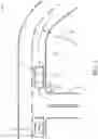
FIG. 2 is a traffic-scenario encountered by the host-vehicle equipped with the system of FIG. 1 in accordance with one embodiment.
DETAILED DESCRIPTION
FIG. 1 illustrates a non-limiting example of an operating system 10, hereafter referred to as the system 10. The system 10 is suitable for use by an automated vehicle, a host-vehicle 12 for example. As used herein, the term automated vehicle may apply to instances when the host-vehicle 12 is being operated in an automated-mode 14, i.e. a fully autonomous mode, where a human-operator (not shown) of the host-vehicle 12 may do little more than designate a destination in order to operate the host-vehicle 12. However, full automation is not a requirement. It is contemplated that the teachings presented herein are useful when the host-vehicle 12 is operated in a manual-mode 16 where the degree or level of automation may be little more than providing an audible or visual warning to the human-operator who is generally in control of the steering, accelerator, and brakes of the host-vehicle 12. For example, the system 10 may merely assist the human-operator as needed to avoid interference with and/or a collision with, for example, an object such as another-vehicle, a pedestrian, or a road sign.
The system 10 includes a failure-detector 20 that detects a component-failure 22 of a component on the host-vehicle 12. FIG. 1 illustrates the failure-detector 20 as being integrated into or part of a controller 24 of the system 10; however this is not a requirement. It is contemplated that the failure-detector 20 could be part of a separate engine-control-module (ECM) or a body-control-module (BCM) of the host-vehicle 12, and the failures could be communicated to the controller 24 on a data-buss of the host-vehicle 12, e.g. via a controller-area-network (CAN) buss. Non-limiting examples component failures of vehicle components whose failure could affect the operation of the host-vehicle 12 include, but are not limited to, a flat-tire 26, an engine-fault 28 (fuel-injector failure, engine-sensor failure), a perception-sensor failure (e.g. camera, radar, lidar; not shown), an anti-wheel-lock-sensor failure (not shown), a vehicle-accelerometer failure (not shown), an exterior-light failure (e.g. headlight or taillight; not shown), a low fluid level (oil, coolant, windshield-washer-fluid), and the like.
The controller 24 may include a processor (not specifically shown) such as a microprocessor or other control circuitry such as analog and/or digital control circuitry including an application specific integrated circuit (ASIC) for processing data as should be evident to those in the art. The controller 24 may include memory (not specifically shown), including non-volatile memory, such as electrically erasable programmable read-only memory (EEPROM) for storing one or more routines, thresholds, and captured data. The one or more routines may be executed by the processor to perform steps for operating the host-vehicle 12 as described herein.
The controller 24 operates the host-vehicle 12, e.g. controls steering and acceleration/braking, based on a dynamic-model 30. As used herein, the dynamic-model 30 represents a dynamic characterization of how the host-vehicle 12 will respond to various situations or stimuli. For example, the dynamic-model 30 may be used to predict a stopping-distance of the host-vehicle 12 based on information about traction-conditions (e.g. wet vs. dry roadway), roadway-slope (e.g. uphill/downhill vs. level), and the like. Prior examples of dynamic-models presume that all components on the vehicle being modeled are operating within normal parameters. For example, the prior dynamic-models presume that the tire-pressures in the tires of the vehicle are within some nominal range. However, if a flat-tire occurred, the prior dynamic-models are not particularly useful as they don't adapt to changes in dynamic behavior of the vehicle due to the flat-tire. The system 10 described herein is an improvement over the prior examples of dynamic-models because the dynamic-model 30 of the host-vehicle 12 is varied based on the component-failure 22 detected by the failure-detector 20.
FIG. 2 illustrates a non-limiting example of a traffic-scenario 32 that the host-vehicle 12, which is equipped with the system 10, may encounter. In this example, the host-vehicle 12 has recently turned onto a roadway 34 from a side-road 36. By way of example and not limitation, the dynamic-model 30 (FIG. 1) for the host-vehicle 12 may specify a maximum-acceleration 38 of the host-vehicle 12 that is considered prior to turning onto the roadway 34 so as to not interfere with an approaching-vehicle 40. That is, the system 10 may use the dynamic-model 30 to predict if the act of the host-vehicle 12 turning onto the roadway 34 will force the approaching-vehicle 40 to slow-down or decelerate an undesirable amount to avoid a collision with the host-vehicle 12. However, if there is something wrong with the engine of the host-vehicle 12, the host-vehicle 12 may not be able to accelerate at a rate comparable to the maximum-acceleration 38.
To address this situation, the system 10 may include an engine-status-detector 42 that operates to determine if the engine of the host-vehicle 12 is operating normally. The engine-status-detector 42 may be fully embedded in an engine-control-module (ECM, not shown) that outputs codes on a data-bus to indicate the operational status of the engine, as will be recognized by those in the art. If the engine is not operating properly, the component-failure 22 may be characterized as an engine-fault 28 when the engine of the host-vehicle 12 is operating at reduced-power, is operating in a limp-home mode. Accordingly, the maximum-acceleration 38 parameter of the dynamic-model 30 may be decreased when the engine of the host-vehicle 12 is operating at a reduced-power 44. As a result, the system 10 may decide to not turn onto the roadway 34 when the approaching-vehicle 40 is detected. As such, the dynamic-model 30 is varied based on the component-failure 22 detected by the failure-detector 20.
The system 10 may include a tire-pressure-detector 46, i.e. a tire-pressure-indicator. The component-failure 22 may indicate that the flat-tire 26 has occurred when a tire-pressure 48 is less than a pressure-threshold 50. The pressure-threshold 50 may be just barely above a completely flat-tire, or may be a pressure less than the recommended-pressure for a given tire where the dynamic behavior of the host-vehicle 12 is noticeably affected. It is also contemplated that multiple values of the pressure-threshold 50 may be used to continually adjust the dynamic-model 30 so that the flat-tire 26 covers both instances of a soft-tire and completely flat-tire. How the dynamic-model 30 is adjusted or varied may be determined by empirical testing and/or computer modeling. In situations when the host-vehicle is being operated on the manual-mode 16 where a human-operator is steering the host-vehicle 12, the adjustments to the dynamic model may be used by, for example, a lane-keeping-system that only operates to steer the host-vehicle when the operator allows the host-vehicle to deviate too far from the center of a travel-lane.
As a non-limiting example, if one of the front tires, e.g. the wheel 72 (FIG. 2), is soft or flat, the steering behavior may be asymmetrical. That is, the magnitude of change in direction of the host-vehicle 12 arising from a given magnitude of the steering-angle 62 for a left-turn may differ from that for a right-turn. For example, if the wheel 72 is the flat-tire 26, it may take a greater magnitude of the steering-angle 62 to turn the host-vehicle to the right that to make the same amount of turn to the left. The dynamic-model 30 may be varied or adjusted to anticipate this asymmetric behavior by increasing the expected change in steering necessary to steer the host-vehicle 12 through an upcoming curve.
The system 10 may include a steering-torque-detector 52 that monitors the amount steering torque applied to a hand-wheel (i.e. steering-wheel, not shown) operated by a human operator, or applied by an automated steering actuator of the host-vehicle 12. The component-failure 22 may indicate that a flat-tire 26 has occurred when a steering-torque 54 necessary to keep the host-vehicle 12 centered in a travel-lane 56 (FIG. 2) is greater than a torque-threshold 58. That is, the flat-tire 26 may cause the host-vehicle 12 to ‘pull’ in one direction, so a compensating steering torque is necessary to keep the host-vehicle 12 traveling near the center of the travel-lane 56. It is recognized that there are causes other than the flat-tire 26 that require a compensating steering torque to keep the host-vehicle 12 traveling near the center of the travel-lane 56. For example, a bent or worn suspension component may cause the same effect and the dynamic-model 30 may be adjusted to compensate in the same manner.
The system 10 may include a steering-angle-detector 60, and the component-failure 22 indicates that a flat-tire 26 has occurred when a steering-angle 62 necessary to keep the host-vehicle centered in the travel-lane 56 is greater than an angle-threshold 64. The effect on the dynamic behavior of the host-vehicle 12 due to the flat-tire 26 may be similar to the above described idea for compensating or adjusting the dynamic-model 30 based on the steering-torque 54. However, a commercially available example of the steering-angle-detector 60 may be more economical than a commercially available example of the steering-torque-detector 52.
The system 10 may include a wheel-speed-detector 66, and the component-failure 22 indicates that a flat-tire 26 has occurred when a wheel-speed 68 of a wheel 72 (FIG. 2) of the host-vehicle 12 does not correspond to a vehicle-speed 70 of the host-vehicle 12. Vehicles with anti-lock or anti-skid braking systems have a wheel-speed-detector at each wheel of a vehicle. The vehicle-speed 70 may be determined by taking an average wheel-speed of three wheels out of the four wheels that most agree with each other, and the fourth wheel that indicates a wheel speed most different from the other three may be presumed to be flat if the difference is greater than some threshold, one kilometer-per-hour (1 kph) for example. Alternatively, the vehicle-speed 70 may be determined using an independent means such as radar or lidar if the host-vehicle 12 is so equipped.
Once the component-failure 22 is identified, one or aspects or characteristics of the dynamic-model 30 may be varied, altered, or otherwise modified so the controller 24 has a version of the dynamic-model 30 that allows the system 10 to anticipate how the host-vehicle 12 is expected to respond to various inputs such as changes in the steering-angle 62, application of the brakes of the host-vehicle 12, or increasing engine power to accelerate the host-vehicle 12. By way of example and not limitation, the dynamic-model 30 may specify a maximum-curve-speed 74 for a curve-radius 76 of an upcoming curve of the travel-lane 56 (FIG. 2). If the component-failure 22 is something that reduces the ability of the host-vehicle 12 to safely navigate the upcoming curve, the dynamic-model 30 may be varied so the maximum-curve-speed 74 is decreased for a specified value of the curve-radius 78 when the component-failure 22 is, for example, a flat-tire 26, or a broken shock-absorber or spring of the suspension-system of the host-vehicle. Similarly, the dynamic-model 30 may specify a braking-distance 78 for a vehicle-speed 70 of the host-vehicle 12, and the braking-distance 78 may be increased when the component-failure 22 is a flat-tire 26.
Accordingly, an operating system (the system 10), a controller 24 for the system 10, and a method of operating the system 10 is provided. The dynamic-model 30 provides a means for the controller 24 to predict the dynamic-behavior of the host-vehicle 12 during various transient maneuvers such as cornering and braking. However, it has been observed that some types or instances of the component-failure 22 can change the dynamic-behavior. To overcome this change the dynamic-model 30 is varied or altered so that the dynamic-behavior of the host-vehicle 12 while the component-failure 22 is present can be predicted.
While this invention has been described in terms of the preferred embodiments thereof, it is not intended to be so limited, but rather only to the extent set forth in the claims that follow.
Claims
We claim:1. An operating system for an automated vehicle, said system comprising:
a failure-detector that detects a component-failure on a host-vehicle; and
a controller that operates the host-vehicle based on a dynamic-model, wherein the dynamic-model is varied based on the component-failure detected by the failure-detector.
Images & Drawings included:
Sources:
- United States Patent and Trademark Office - verify current appl. status at the USPTO↗
Similar patent applications:
- » 20180364721
Adaptive dynamic model for automated vehicle
Recent applications in this class:
- » 20250147510 2025-05-08
AGRICULTURAL VEHICLE, CONTROL DEVICE, AND CONTROL METHOD - » 20250138534 2025-05-01
SAFETY PROCEDURE ANALYSIS FOR COLLISION AVOIDANCE IN AUTONOMOUS AND SEMI-AUTONOMOUS SYSTEMS AND APPLICATIONS - » 20250138533 2025-05-01
DYNAMIC INDOOR NAVIGATION - » 20250130568 2025-04-24
SYSTEMS AND METHODS FOR USING RISK PROFILES FOR CREATING AND DEPLOYING NEW VEHICLE EVENT DEFINITIONS TO A FLEET OF VEHICLES - » 20250117010 2025-04-10
METHOD FOR DETERMINING OPTIMAL MACHINE PERFORMANCE DURING AUTONOMOUS OPERATION - » 20250103047 2025-03-27
NAVIGATION SYSTEM FOR A VISUALLY IMPAIRED USER AND A METHOD OF NAVIGATING A VISUALLY IMPAIRED USER - » 20250068164 2025-02-27
MOVING OBJECT CONTROL SYSTEM, MOVING OBJECT, CONTROL METHOD, AND STORAGE MEDIUM - » 20250068163 2025-02-27
SYSTEMS AND METHODS FOR OPTIMIZING ROUTE PLANNING FOR TIGHT TURNS FOR ROBOTIC APPARATUSES - » 20250044799 2025-02-06
Automation Control Using Stop Trajectories - » 20250028320 2025-01-23
Systems And Methods For A Robotic Cart
Recent applications for this Assignee:
- » 20250162584 2025-05-22
ESTIMATING SPEED PROFILES - » 20250029412 2025-01-23
DETERMINING OBJECT MOBILITY PARAMETERS USING AN OBJECT SEQUENCE - » 20240140458 2024-05-02
Processing a request signal regarding operation of an autonomous vehicle - » 20240132112 2024-04-25
Path-based trajectory prediction - » 20240131984 2024-04-25
TURN SIGNAL ASSIGNMENT FOR COMPLEX MANEUVERS - » 20240129604 2024-04-18
Plenoptic sensor devices, systems, and methods - » 20240127579 2024-04-18
Identifying new classes of objects in environments of vehicles - » 20240127534 2024-04-18
Color map layer for annotation - » 20240124016 2024-04-18
Ensemble-based vehicle motion planner - » 20240122780 2024-04-18
AUTONOMOUS VEHICLE WITH AUDIO USER GUIDANCE