SUBSTRATE POLISHING APPARATUS
US20260145296A1
2026-05-28
19/325,918
2025-09-11
Smart Summary: A polishing machine is designed to smooth surfaces using a special pad. It has two lights that shine on the pad to help with the polishing process. The pad is made with a sticky material that holds tiny particles that can help clean. Additionally, the machine has a system to add a lubricant to the pad, making it easier to polish. Overall, this setup helps create a smoother surface more effectively. 🚀 TL;DR
Abstract:
A substrate polishing apparatus includes a polishing pad, a first light source that radiates first light to the polishing pad, a second light source that radiates second light to the polishing pad, and a lubricant supply device that supplies a lubricant to the polishing pad. The polishing pad includes a binder and photocatalytic particles in the binder.
Assignee:
- SAMSUNG ELECTRONICS CO., LTD. 95,539 🇰🇷 Suwon-si, South Korea
Applicant:
Interested in similar patents?
Get notified when new applications in this technology area are published.
Classification:
B24B37/34 » CPC main
Lapping machines or devices; Accessories Accessories
B24B37/14 » CPC further
Lapping machines or devices; Accessories; Lapping tools; Lapping plates for working plane surfaces characterised by the composition or properties of the plate materials
B24B57/02 » CPC further
Devices for feeding, applying, grading or recovering grinding, polishing or lapping agents for feeding of fluid, sprayed, pulverised, or liquefied grinding, polishing or lapping agents
B24B57/04 » CPC further
Devices for feeding, applying, grading or recovering grinding, polishing or lapping agents for feeding of solid grinding, polishing or lapping agents
B24D3/342 » CPC further
Physical features of abrasive bodies, or sheets, e.g. abrasive surfaces of special nature; Abrasive bodies or sheets characterised by their constituents characterised by additives enhancing special physical properties, e.g. wear resistance, electric conductivity, self-cleaning properties incorporated in the bonding agent
B24D3/34 IPC
Physical features of abrasive bodies, or sheets, e.g. abrasive surfaces of special nature; Abrasive bodies or sheets characterised by their constituents characterised by additives enhancing special physical properties, e.g. wear resistance, electric conductivity, self-cleaning properties
Description
CROSS-REFERENCE TO RELATED APPLICATIONS
This application is based on and claims priority under 35 U.S.C. §119 of Korean Patent Application No. 10-2024-0168633, filed on Nov. 22, 2024, the entire contents of which are hereby incorporated by reference.
BACKGROUND
The disclosure relates to a substrate polishing apparatus, and more particularly, to a substrate polishing apparatus including a polishing pad.
Semiconductor devices may be manufactured through multiple processes. For example, semiconductor devices may be manufactured through a photolithography process, etching process, and deposition process, and the like on a substrate. Prior to each of these processes, it may be necessary to planarize a surface of the substrate. To this end, a polishing process may be performed on the substrate. The polishing process may be performed using various methods. For example, a chemical mechanical polishing (CMP) process may be used to planarize the substrate.
SUMMARY
Aspects of the disclosure provide a substrate polishing apparatus with improved polishing power.
According to an aspect of the disclosure, there is provided a substrate polishing apparatus including: a polishing pad; a first light source configured to radiate first light having a first wavelength on the polishing pad; a second light source configured to radiate second light having a second wavelength on the polishing pad; and a lubricant supply device configured to supply a lubricant to the polishing pad, wherein the polishing pad includes: a binder; and a photocatalytic particle in the binder, and wherein the first wavelength of the first light is smaller than the second wavelength of the second light.
According to another aspect of the disclosure, there is provided a substrate polishing apparatus including: a polishing pad; a light source configured to radiate light on the polishing pad; and a lubricant supply device configured to supply a lubricant to the polishing pad, wherein the polishing pad includes: a binder; and a plurality of photocatalytic particles in the binder, wherein the binder includes: a base part; a plurality of protrusions protruding from the base part; and a groove between adjacent protrusions, among the plurality of protrusions, and wherein the plurality of photocatalytic particles include: a plurality of first photocatalytic particles penetrating an upper surface of each of the plurality of protrusions; and a plurality of second photocatalytic particles penetrating a sidewall of each of the plurality of protrusions.
According to another aspect of the disclosure, there is provided a substrate polishing apparatus including: a platen; a sub pad on the platen; a polishing pad on the sub pad; a first light source configured to radiate first light on the polishing pad; a second light source configured to radiate second light on the polishing pad; and a lubricant supply device configured to supply a lubricant to the polishing pad, wherein the polishing pad includes: a binder; and a plurality of photocatalytic particles in the binder, wherein the binder includes: a base part; and a plurality of protrusions protruding from the base part; and a groove between adjacent protrusions among the plurality of protrusions, and wherein the plurality of photocatalytic particles include: a plurality of first photocatalytic particles in the plurality of protrusions; and a plurality of second photocatalytic particles in the base part.
BRIEF DESCRIPTION OF DRAWINGS
The accompanying drawings are included to provide a further understanding of the inventive concept, and are incorporated in and constitute a part of this specification. The drawings illustrate embodiments of the inventive concept and, together with the description, serve to explain principles of the inventive concept. In the drawings:
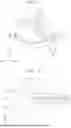
FIG. 1 is a perspective view of a substrate polishing apparatus according to some embodiments;
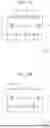
FIG. 2 is a plan view of the substrate polishing apparatus of FIG. 1;
FIG. 3 is a plan view of a polishing pad of the substrate polishing apparatus of FIG. 1;
FIG. 4 is a cross-sectional view of the polishing pad, a sub pad, and a platen of the substrate polishing apparatus of FIG. 1;
FIG. 5 is an enlarged view of the region Q1 of FIG. 3;
FIG. 6 is a cross-sectional view taken along line A-A′ of FIG. 5;
FIG. 7 is a flowchart illustrating a method of operating a substrate polishing apparatus according to some embodiments;
FIG. 8 is a diagram for describing a method of operating a substrate polishing apparatus according to some embodiments;
FIGS. 9A, 9B, and 9C are diagrams illustrating a polishing pad according to a method of operating a substrate polishing apparatus according to some embodiments;
FIGS. 10A and 10B are diagrams for describing a polishing pad of a substrate polishing apparatus according to some embodiments;
FIGS. 11A and 11B are diagrams for describing a polishing pad of a substrate polishing apparatus according to some embodiments;
FIGS. 12A and 12B are diagrams for describing a polishing pad of a substrate polishing apparatus according to some embodiments;
FIG. 13 is a diagram for describing a polishing pad of a substrate polishing apparatus according to some embodiments;
FIG. 14 is a diagram for describing a polishing pad of a substrate polishing apparatus according to some embodiments;
FIG. 15 is a diagram for describing a polishing pad of a substrate polishing apparatus according to some embodiments;
FIG. 16 is a diagram for describing a polishing pad of a substrate polishing apparatus according to some embodiments;
FIG. 17 is a diagram for describing a polishing pad of a substrate polishing apparatus according to some embodiments;
FIG. 18 is a diagram for describing a polishing pad of a substrate polishing apparatus according to some embodiments;
FIG. 19 is a diagram for describing a polishing pad of a substrate polishing apparatus according to some embodiments;
FIGS. 20A and 20B are diagrams for describing a polishing pad of a substrate polishing apparatus according to some embodiments;
FIGS. 21A and 21B are diagrams for describing a polishing pad of a substrate polishing apparatus according to some embodiments;
FIGS. 22A and 22B are diagrams for describing a polishing pad of a substrate polishing apparatus according to some embodiments;
FIGS. 23A and 23B are diagrams for describing a polishing pad of a substrate polishing apparatus according to some embodiments;
FIG. 24 is a plan view of a substrate polishing apparatus according to some embodiments;
FIG. 25 is a plan view of a substrate polishing apparatus according to some embodiments;
FIG. 26 is a plan view of a substrate polishing apparatus according to some embodiments; and
FIG. 27 is a diagram illustrating a substrate polishing apparatus according to some embodiments.
DETAILED DESCRIPTION
Hereinafter, embodiments of the disclosure will be described with reference to the accompanying drawings. Like reference numerals may refer to like elements throughout the disclosure.
FIG. 1 is a perspective view of a substrate polishing apparatus according to some embodiments. FIG. 2 is a plan view of the substrate polishing apparatus of FIG. 1. FIG. 3 is a plan view of a polishing pad of the substrate polishing apparatus of FIG. 1. FIG. 4 is a cross-sectional view of the polishing pad, a sub pad, and a platen of the substrate polishing apparatus of FIG. 1. FIG. 5 is an enlarged view of the region Q1 of FIG. 3. FIG. 6 is a cross-sectional view taken along line A-A′ of FIG. 5.
Referring to FIGS. 1 and 2, the substrate polishing apparatus may be a chemical mechanical polishing (CMP) apparatus for polishing a surface of a substrate WF. In some embodiments, the substrate WF may include, but is not limited to, a semiconductor substrate, an insulator substrate, or a semiconductor on insulator (SOI) substrate. The semiconductor substrate may include, but is not limited to, a silicon substrate.
The substrate polishing apparatus may include a polishing pad 10, a polishing head 20, a first light radiation device 30, a second light radiation device 40, a lubricant supply device 50, a sub pad 60, and a platen 70.
The platen 70 may have a shape of a circular plate including an upper surface parallel to a first direction D1 and a second direction D2. The first direction D1 and the second direction D2 may intersect each other. For example, the first direction D1 and the second direction D2 may be perpendicular to each other.
The sub pad 60 may be provided on the platen 70. The polishing pad 10 may be provided on the sub pad 60. In some embodiments, the platen 70, the sub pad 60, and the polishing pad 10 may be coupled to each other. In some embodiments, the polishing pad 10 may be separated from the sub pad 60 and replaced with another polishing pad 10.
The platen 70, the sub pad 60, and the polishing pad 10 may be rotated around a central axis that is in a third direction D3. The third direction D3 may intersect the first direction D1 and the second direction D2. For example, the third direction D3 may be a vertical direction perpendicular to the first direction D1 and the second direction D2.
According to an embodiment, the platen 70 may be rotated by a driving unit or a driver. For example, the platen 70 may include a driving unit and may be rotated by the driving unit. According to an embodiment, a controller may output a control signal to control one or more operations of the substrate polishing apparatus. For example, the controller may control the driving unit to rotate the platen 70. The driving unit may include, but is not limited to, a motor. In some embodiments, the sub pad 60 coupled to the platen 70 may be rotated based on the rotation of the platen 70, and the polishing pad 10 coupled to the sub pad 60 may be rotated based on the rotation of the sub pad 60.
The polishing head 20 may overlap the polishing pad 10 in the third direction D3. For example, the polishing head 20 may be provided above the polishing pad 10 in the third direction D3. The polishing head 20 may be provided on the polishing pad 10. The polishing head 20 may support or fix the substrate WF. The substrate WF may be provided between the polishing head 20 and the polishing pad 10, and a surface of the substrate WF may be exposed towards the polishing pad 10. The polishing head 20 may be rotated around a central axis that is in the third direction D3. The polishing head 20 may be rotated independent of the polishing pad 10. The polishing head 20 may rotate the substrate WF.
The polishing head 20 may include a body 20 and a support part 22. The body 21 may support or fix the substrate WF. The support part 22 may be coupled to the body 21. The support part 22 may include a driving unit and may be rotated by the driving unit. The driving unit may be a motor, for example. The body 21 coupled to the support part 22 may be rotated due to rotation of the support part 22.
The lubricant supply device 50 may overlap the polishing pad 10 in the third direction D3. The lubricant supply device 50 may be spaced apart from the polishing pad 10 in the third direction D3. The lubricant supply device 50 may be provided on or above the polishing pad 10. The lubricant supply device 50 may supply a lubricant onto the polishing pad 10. The lubricant may include, but is not limited to, at least one of deionized water, booster, inhibitor, dispersant, or pH adjuster.
The first light radiation device 30 may overlap the polishing pad 10 in the third direction D3. The first light radiation device 30 may be spaced apart from the polishing pad 10 in the third direction D3. The first light radiation device 30 may be provided on or above the polishing pad 10. According to an embodiment, a portion of the first light radiation device 30 may extend beyond an outer edge of the polishing pad 10. However, the disclosure is not limited hereto, and as such, according to another embodiment, entirety of the first light radiation device 30 may be provided on or above the polishing pad 10.
The first light radiation device 30 may include a first light source 31 and a first light case 32. The first light case 32 may include an empty space therein. The first light source 31 may be provided in the empty space in the first light case 32. The first light case 32 may include sidewalls surrounding the first light source 31 and an upper portion connecting the sidewalls. The empty space of the first light case 32 may be defined by the sidewalls and the upper portion of the first light case 32. The empty space of the first light case 32 may be surrounded by the sidewalls of the first light case 32. The empty space of the first light case 32 may communicate with a space below the first light case 32. The empty space of the first light case 32 may be opened downwards from the first light case 32.
The first light case 32 may have a bar shape extending in one direction. However, the disclosure is not limited thereto, and as such, the first light case 32 may have another shape. For example, the first light case 32 may extend in the first direction D1. The first light case 32 may overlap the polishing pad 10 in the third direction D3. The first light case 32 may be spaced apart from the polishing pad 10 in the third direction D3. The first light case 32 may be provided on or above the polishing pad 10.
The first light source 31 may extend in one direction. For example, the first light source 31 may extend in the first direction D1. The first light source 31 may have a cylindrical shape extending in one direction. However, the disclosure is not limited thereto, and as such, the first light source 31 may have another shape. The first light source 31 may overlap the polishing pad 10 in the third direction D3. The first light source 31 may be spaced apart from the polishing pad 10 in the third direction D3. The first light source 31 may be provided on or above the polishing pad 10.
The first light source 31 may emit light. The first light source 31 may include, but is not limited to, an optical scanner, a lamp, or a laser source.
According to an embodiment, the first light source 31 may radiate first light to the polishing pad 10. The first light emitted upwards from the first light source 31 may be blocked by the first light case 32. The first light emitted sideward from the first light source 31 may be blocked by the first light case 32. The first light emitted downwards from the first light source 31 may be radiated to the polishing pad 10. As such, according to an embodiment, only the first light emitted downwards from the first light source 31 may be radiated to the polishing pad 10. However, the disclosure is not limited thereto.
The second light radiation device 40 may overlap the polishing pad 10 in the third direction D3. The second light radiation device 40 may be spaced apart from the polishing pad 10 in the third direction D3. The second light radiation device 40 may be provided on or above the polishing pad 10. The second light radiation device 40 may be provided adjacent to the first light radiation device 30. According to an embodiment, a portion of the second light radiation device 40 may extend beyond an outer edge of the polishing pad 10. However, the disclosure is not limited hereto, and as such, according to another embodiment, entirety of the second light radiation device 40 may be provided on or above the polishing pad 10.
The second light radiation device 40 may include a second light source 41 and a second light case 42. The second light case 42 may include an empty space therein. The second light source 41 may be provided in the empty space in the second light case 42. The second light case 42 may include sidewalls surrounding the second light source 41 and an upper portion connecting the sidewalls. The empty space of the second light case 42 may be defined by the sidewalls and the upper portion of the second light case 42. The empty space of the second light case 42 may be surrounded by the sidewalls of the second light case 42. The empty space of the second light case 42 may communicate with a space below the second light case 42. The empty space of the second light case 42 may be opened downwards from the second light case 42.
The second light case 42 may have a bar shape extending in one direction. However, the disclosure is not limited thereto, and as such, the second light case 42 may have another shape. For example, the second light case 42 may extend in the first direction D1. The second light case 42 may overlap the polishing pad 10 in the third direction D3. The second light case 42 may be spaced apart from the polishing pad 10 in the third direction D3. The second light case 42 may be provided on or above the polishing pad 10.
The second light source 41 may extend in one direction. For example, the second light source 41 may extend in the first direction D1. The second light source 41 may have a cylindrical shape extending in one direction, for example. However, the disclosure is not limited thereto, and as such, the second light source 41 may have another shape. The second light source 41 may overlap the polishing pad 10 in the third direction D3. The second light source 41 may be spaced apart from the polishing pad 10 in the third direction D3. The second light source 41 may be provided on or above the polishing pad 10.
The second light source 41 may emit light. The second light source 41 may be an optical scanner, a lamp, or a laser source, for example.
According to an embodiment, the second light source 41 may radiate second light to the polishing pad 10. The second light emitted upwards from the second light source 41 may be blocked by the second light case 42. The second light emitted sideward from the second light source 41 may be blocked by the second light case 42. The second light emitted downwards from the second light source 41 may be radiated to the polishing pad 10. As such, according to an embodiment, only the second light emitted downwards from the second light source 41 may be radiated to the polishing pad 10. However, the disclosure is not limited thereto.
According to an embodiment, the first light may have a different characteristic that the second light. For example, the first light may have a shorter wavelength than the second light. The first light may have higher energy than the second light.
Referring to FIGS. 3 and 4, the polishing pad 10 may include a binder 11. The binder 11 may fix abrasive particles 12 and photocatalytic particles 13 that will be described later (for example, FIGS. 5 and 6). For example, the binder 11 may include a polymer material.
The binder 11 may include a base part 11a and protrusions 11b protruding from the base part 11a in the third direction D3. The protrusions 11b may be spaced apart from each other. The protrusions 11b may each have a circular ring shape in a plan view of FIG. 3. The outermost protrusion 11b among the protrusions 11b may surround the remaining protrusions 11b.
Grooves GR may be provided between the protrusions 11b. The groove GR may be provided between two protrusions 11b adjacent to each other. Sidewalls of the groove GR may be defined by sidewalls of the protrusions 11b. A lower surface of the groove GR may be defined by an upper surface of the base part 11a. Each of the grooves GR may have a circular ring shape in a plan view of FIG. 3. The groove GR may function as a passage for discharging by-products of a polishing process.
The base part 11a may be connected or coupled to the sub pad 60. A lower surface of the base part 11a may be in contact with an upper surface of the sub pad 60. The base part 11a may be provided between the protrusions 11b and the sub pad 60.
Referring to FIGS. 5 and 6, the polishing pad 10 may further include the abrasive particles 12 and the photocatalytic particles 13.
In some embodiments, the polishing pad 10 may be manufactured through a 3D printing process. The 3D printing process may include, but is not limited to, a process of spraying a prepolymer solution containing photocatalytic particles and abrasive particles and a curing process using a heat treatment or ultraviolet (UV) radiation.
The abrasive particles 12 may serve to polish the substrate WF during a polishing process. For example, the abrasive particles 12 may include, but is not limited to, at least one of SiO2, CeO2, Al2O3, or ZrO2.
The photocatalytic particles 13 may include a different material from the abrasive particles 12. The photocatalytic particles 13 may include a photocatalytic material. For example, the photocatalytic particles 13 may include, but is not limited to, at least one of TiO2, WO3, ZnO, SnO2, Fe2O3, Fe3O4, Cu2O, or BiWO4.
The photocatalytic particles 13 and the abrasive particles 12 may be connected to the binder 11. The photocatalytic particles 13 and the abrasive particles 12 may be in contact with the binder 11. The photocatalytic particles 13 and the abrasive particles 12 may be fixed to the binder 11. The photocatalytic particles 13 and the abrasive particles 12 may be spaced apart from each other.
Referring to FIG. 6, the abrasive particles 12 may include first abrasive particles 12a penetrating an upper surface 11b_U of the protrusion 11b, second abrasive particles 12b penetrating a sidewall 11b_S of the protrusion 11b, third abrasive particles 12c penetrating an upper surface 11a_U of the base part 11a, fourth abrasive particles 12d in the protrusion 11b, and fifth abrasive particles 12e in the base part 11a.
A lower portion of the first abrasive particle 12a may be provided in the protrusion 11b and an upper portion of the first abrasive particle 12a may be exposed above the protrusion 11b. A first portion of the second abrasive particle 12b may be provided in the protrusion 11b and a second portion of the second abrasive particle 12b may be exposed to the groove GR. A lower portion of the third abrasive particle 12c may be provided in the base part 11a and an upper portion of the third abrasive particle 12c may be exposed to the groove GR. An entire surface of the fourth abrasive particle 12d may be provided in the protrusion 11b. For example, an entire surface of the fourth abrasive particle 12d may be covered by the protrusion 11b. An entire surface of the fifth abrasive particle 12e may be provided in the base part 11a. For example, an entire surface of the fifth abrasive particle 12e may be covered by the base part 11a.
The photocatalytic particles 13 may include first photocatalytic particles 13a penetrating the upper surface 11b_U of the protrusion 11b, second photocatalytic particles 13b penetrating the sidewall 11b_S of the protrusion 11b, third photocatalytic particles 13c penetrating the upper surface 11a_U of the base part 11a, fourth photocatalytic particles 13d in the protrusion 11b, and fifth photocatalytic particles 13e in the base part 11a.
A lower portion of the first photocatalytic particle 13a may be provided in the protrusion 11b and an upper portion of the first photocatalytic particle 13a may be exposed above the protrusion 11b. A first portion of the second photocatalytic particle 13b may be provided in the protrusion 11b and a second portion of the second photocatalytic particle 13b may be exposed to the groove GR. A lower portion of the third photocatalytic particle 13c may be provided in the base part 11a and an upper portion of the third photocatalytic particle 13c may be exposed to the groove GR. An entire surface of the fourth photocatalytic particle 13d may be provided in the protrusion 11b. An entire surface of the fourth photocatalytic particle 13d may be covered with the protrusion 11b. An entire surface of the fifth photocatalytic particle 13e may be provided in the base part 11a. An entire surface of the fifth photocatalytic particle 13e may be covered with the base part 11a.
According to some embodiments, the first light radiation device 30 and the second light radiation device 40 in the substrate polishing apparatus may maintain a surface roughness of the polishing pad 10 to be relatively constant using the photocatalytic particles 13 in the polishing pad 10. Accordingly, an additional device for managing the surface roughness of the polishing pad 10 may be omitted. Furthermore, since by-products produced during a polishing process may be removed, scratches of the substrate WF due to the by-products may be reduced.
According to some embodiments, since the polishing pad 10 includes the abrasive particles 12 in the substrate polishing apparatus, uniformity of the polishing process may be improved.
FIG. 7 is a flowchart illustrating a method of operating a substrate polishing apparatus according to some embodiments. FIG. 8 is a diagram for describing a method of operating a substrate polishing apparatus according to some embodiments. FIGS. 9A, 9B, and 9C are diagrams illustrating a polishing pad according to a method of operating a substrate polishing apparatus according to some embodiments.
Referring to FIGS. 7 and 8, a method of operating a polishing apparatus may include fixing the substrate WF to the polishing head 20 (S10) and performing a polishing process (S20). The performing of the polishing process (S20) may include rotating the polishing pad 10 and the polishing head 20, radiating, by the first light source 31, first light L1 to the polishing pad 10, radiating, by the second light source 41, second light L2 to the polishing pad 10, and supplying, by the lubricant supply device 50, a lubricant LU to the polishing pad 10. The performing of a polishing process (S20) may include causing the substrate WF and the polishing pad 10 to be in contact with each other and rub each other.
Referring to FIGS. 7, 8, and 9A, the performing of the polishing process (S20) may include removing by-products PD using the second light L2 (S21). For example, by-products PD may be formed on the polishing pad 10 as the polishing process is performed. For example, the by-products PD may be formed due to wear of the binder 11. For example, the by-products PD may be formed due to a lubricant.
In an example case in which the second light L2 is radiated, a low-activity photocatalytic action may occur in the photocatalytic particles 13. Energy of the second light L2 may be higher than band gap energy of the photocatalytic particles 13, and a low-activity photocatalytic action may occur in the photocatalytic particles 13. Since the low-activity photocatalytic action occurs, the by-products PD may be decomposed and removed by the energy of the second light L2.
Referring to FIGS. 7, 8, and 9B, the performing of a polishing process (S20) may include reducing a size of photocatalytic particles (S22). When the polishing process is performed, the abrasive particles 12, the photocatalytic particles 13, and the binder 11 may be worn.
The abrasive particles 12 may be reduced in size due to wear. A size of a worn abrasive particle w12 may be smaller than a size of a non-worn abrasive particle 12. The photocatalytic particles 13 may be reduced in size due to wear. A size of a worn photocatalytic particle w13 may be smaller than a size of a non-worn photocatalytic particle 13. Due to the reduction in size, band gap energy of the worn photocatalytic particle w13 may be higher than band gap energy of the non-worn photocatalytic particle 13.
Referring to FIGS. 7, 8, and 9C, the performing of a polishing process (S20) may include removing the photocatalytic particles 13 using the first light L1 (S23). In an example case in which the first light L1 is radiated, a high-activity photocatalytic action may occur in the worn photocatalytic particles w13.
Energy of the first light L1 may be higher than band gap energy of the worn photocatalytic particles w13, and a high-activity photocatalytic action may occur in the worn photocatalytic particles w13. In some embodiments, the energy of the second light L2 may be lower than the band gap energy of the worn photocatalytic particles w13, and a photocatalytic action may not be induced by the second light L2 in the worn photocatalytic particles w13.
Since the high-activity photocatalytic action occurs, a portion of the binder 11 around the worn photocatalytic particles w13 may be decomposed by the energy of the first light L1, and the worn photocatalytic particles w13 may be separated from the binder 11. In some embodiments, the binder 11 may not be decomposed by the low-activity photocatalytic action.
The abrasive particles w12 worn through the polishing process may be further worn and separated from the binder 11.
Since the worn photocatalytic particles w13 and the worn abrasive particles w12 are separated from the binder 11, a surface of the binder 11 may become rough.
When the polishing process progresses, the surface of the binder 11 becoming smooth due to polishing and the surface of the binder 11 becoming rough due to separation of the worn photocatalytic particles w13 and the worn abrasive particles w12 may be repeated. For example, as the polishing process progresses, the binder 11 may be grinded to expose a next layer of photocatalytic particles 13 and abrasive particles 12, and such a process may be repeated. Accordingly, the surface roughness of the polishing pad 10 may be maintained constant relatively.
FIGS. 10A and 10B are diagrams for describing a polishing pad of a substrate polishing apparatus according to some embodiments. FIG. 10A may correspond to FIG. 5, and FIG. 10B may correspond to FIG. 6. The substrate polishing apparatus according to FIGS. 10A and 10B may be similar to the substrate polishing apparatus according to FIGS. 1 to 6, and as such, similar or redundant description may be omitted, except for matters described below.
Referring to FIGS. 10A and 10B, a polishing pad 110 may include photocatalytic particles 113. The polishing pad 110 may not include abrasive particles.
According to an embodiment, the lubricant supply device 50 (FIGS. 1A and 1B) may supply a lubricant and abrasive particles to the polishing pad 110.
FIGS. 11A and 11B are diagrams for describing a polishing pad of a substrate polishing apparatus according to some embodiments. FIG. 11A may correspond to FIG. 5. FIG. 11B may correspond to FIG. 6. The substrate polishing apparatus according to FIGS. 11A and 11B may be similar to the substrate polishing apparatus according to FIGS. 1 to 6, and as such, similar or redundant description may be omitted, except for matters described below.
Referring to FIGS. 11A and 11B, a polishing pad 210 may include photocatalytic particles 213 and abrasive particles 212. The photocatalytic particles 213 may each be in contact with a plurality of abrasive particles 212. The plurality of abrasive particles 212 may be in contact with a single photocatalytic particle 213. A size of the abrasive particle 212 may be smaller than a size of the photocatalytic particle 213. However, the disclosure is not limited thereto, and as such, the size of the abrasive particle 212 and the size of the photocatalytic particle 213 may vary.
FIGS. 12A and 12B are diagrams for describing a polishing pad of a substrate polishing apparatus according to some embodiments. FIG. 12A may correspond to FIG. 5. FIG. 12B may correspond to FIG. 6. The substrate polishing apparatus according to FIGS. 12A and 12B may be similar to the substrate polishing apparatus according to FIGS. 1 to 6, and as such, similar or redundant description may be omitted, except for matters described below.
Referring to FIGS. 12A and 12B, a polishing pad 310 may include photocatalytic particles 313 and abrasive particles 312. The abrasive particles 312 may each be in contact with a plurality of photocatalytic particles 313. The plurality of photocatalytic particles 313 may be in contact with a single abrasive particle 312. A size of the photocatalytic particle 313 may be smaller than a size of the abrasive particle 312.
FIG. 13 is a diagram for describing a polishing pad of a substrate polishing apparatus according to some embodiments. FIG. 13 may correspond to FIG. 6. The substrate polishing apparatus according to FIG. 13 may be similar to the substrate polishing apparatus according to FIGS. 1 to 6, and as such, similar or redundant description may be omitted, except for matters described below.
Referring to FIG. 13, a polishing pad 410 may include abrasive particles 412 and photocatalytic particles 413.
According to an embodiment, a density of the abrasive particles 412 in the base part 11a may be higher than a density of the abrasive particles 412 in the protrusion 11b. The density of the abrasive particles 412 in the protrusion 11b may increase as a level decreases. For example, the density of the abrasive particles 412 in the protrusion 11b may increase in a direction toward the base part 11a. The density of the abrasive particles 412 in an upper portion of the protrusion 11b may be lower than the density of the abrasive particles 412 in a lower portion of the protrusion 11b.
According to an embodiment, a density of the photocatalytic particles 413 in the base part 11a may be higher than a density of the photocatalytic particles 413 in the protrusion 11b. The density of the photocatalytic particles 413 in the protrusion 11b may increase as a level decreases. The density of the photocatalytic particles 413 in the protrusion 11b may increase in a direction toward the base part 11a. The density of the photocatalytic particles 413 in an upper portion of the protrusion 11b may be lower than the density of the photocatalytic particles 413 in a lower portion of the protrusion 11b.
In the substrate polishing apparatus according to some embodiments, the abrasive particles 412 and the photocatalytic particles 413 may be arranged so that the surface roughness of the protrusion 11b increases as the protrusion 11b becomes more worn through the polishing process. However, the disclosure is not limited thereto, and as such, the density of the abrasive particles 412 and the density of the photocatalytic particles 413 may vary.
In some embodiments, the density of the abrasive particles 412 and the photocatalytic particles 413 in the protrusion 11b may decrease as a level decreases, and the surface roughness of the protrusion 11b may decrease as the protrusion 11b becomes more worn.
FIG. 14 is a diagram for describing a polishing pad of a substrate polishing apparatus according to some embodiments. FIG. 14 may correspond to FIG. 6. The substrate polishing apparatus according to FIG. 14 may be similar to the substrate polishing apparatus according to FIGS. 1 to 6, and as such, similar or redundant description may be omitted, except for matters described below.
Referring to FIG. 14, a polishing pad 510 may include abrasive particles 512 and photocatalytic particles 513.
According to an embodiment, a density of the abrasive particles 512 in the base part 11a and a density of the abrasive particles 512 in the protrusion 11b may be the same. The density of the abrasive particles 512 in the protrusion 11b may be constant.
According to an embodiment, a density of the photocatalytic particles 513 in the base part 11a may be higher than a density of the photocatalytic particles 513 in the protrusion 11b. The density of the photocatalytic particles 513 in the protrusion 11b may increase as a level decreases. The density of the photocatalytic particles 513 in the protrusion 11b may increase as the photocatalytic particles 513 become closer to the base part 11a. The density of the photocatalytic particles 513 in an upper portion of the protrusion 11b may be lower than the density of the photocatalytic particles 513 in a lower portion of the protrusion 11b.
In the substrate polishing apparatus according to some embodiments, the photocatalytic particles 513 may be arranged so that the surface roughness of the protrusion 11b increases as the protrusion 11b becomes more worn through the polishing process.
In some embodiments, the density of the photocatalytic particles 513 in the protrusion 11b may decrease as a level decreases, and the surface roughness of the protrusion 11b may decrease as the protrusion 11b becomes more worn.
FIG. 15 is a diagram for describing a polishing pad of a substrate polishing apparatus according to some embodiments. FIG. 15 may correspond to FIG. 6. The substrate polishing apparatus according to FIG. 15 may be similar to the substrate polishing apparatus according to FIGS. 1 to 6, and as such, similar or redundant description may be omitted, except for matters described below.
Referring to FIG. 15, a polishing pad 610 may include abrasive particles 612 and photocatalytic particles 613.
According to an embodiment, a density of the photocatalytic particles 613 in the base part 11a and a density of the photocatalytic particles 613 in the protrusion 11b may be the same. The density of the photocatalytic particles 613 in the protrusion 11b may be constant.
According to an embodiment, a density of the abrasive particles 612 in the base part 11a may be higher than a density of the abrasive particles 612 in the protrusion 11b. The density of the abrasive particles 612 in the protrusion 11b may increase as a level decreases. The density of the abrasive particles 612 in the protrusion 11b may increase in a direction toward the base part 11a. The density of the abrasive particles 612 in an upper portion of the protrusion 11b may be lower than the density of the abrasive particles 612 in a lower portion of the protrusion 11b.
In the substrate polishing apparatus according to some embodiments, the abrasive particles 612 may be arranged so that the surface roughness of the protrusion 11bincreases as the protrusion 11b becomes more worn through the polishing process.
In some embodiments, the density of the abrasive particles 612 in the protrusion 11b may decrease as a level decreases, and the surface roughness of the protrusion 11b may decrease as the protrusion 11b becomes more worn.
FIG. 16 is a diagram for describing a polishing pad of a substrate polishing apparatus according to some embodiments. FIG. 16 may correspond to FIG. 6. The substrate polishing apparatus according to FIG. 16 may be similar to the substrate polishing apparatus according to FIGS. 1 to 6, and as such, similar or redundant description may be omitted, except for matters described below.
Referring to FIG. 16, a polishing pad 710 may include abrasive particles 712 and photocatalytic particles 713.
According to an embodiment, a group of the photocatalytic particles 713 may be provided between groups of the abrasive particles 712 that are spaced apart from each other in a fourth direction D4. The group of abrasive particles 712 may include a plurality of abrasive particles 712. The group of photocatalytic particles 713 may include a plurality of photocatalytic particles 713.
The groups of abrasive particles 712 and the groups of photocatalytic particles 713 may be alternately arranged in the fourth direction D4.
FIG. 17 is a diagram for describing a polishing pad of a substrate polishing apparatus according to some embodiments. FIG. 17 may correspond to FIG. 6. The substrate polishing apparatus according to FIG. 17 may be similar to the substrate polishing apparatus according to FIGS. 1 to 6, and as such, similar or redundant description may be omitted, except for matters described below.
Referring to FIG. 17, a polishing pad 810 may include abrasive particles 812 and photocatalytic particles 813.
According to an embodiment, a density of the abrasive particles 812 in the base part 11a may be higher than a density of the abrasive particles 812 in the protrusion 11b. The density of the abrasive particles 812 in the protrusion 11b may increase as a level decreases.
According to an embodiment, a density of the photocatalytic particles 813 in the base part 11a may be higher than a density of the photocatalytic particles 813 in the protrusion 11b. The density of the photocatalytic particles 813 in the protrusion 11b may increase as a level decreases.
In an upper portion of the protrusion 11b, the abrasive particles 812 and the photocatalytic particles 813 may be alternately arranged in the fourth direction D4.
In the base part 11a and a lower portion of the protrusion 11b, groups of abrasive particles 812 and groups of photocatalytic particles 813 may be alternately arranged in the fourth direction D4.
FIG. 18 is a diagram for describing a polishing pad of a substrate polishing apparatus according to some embodiments. FIG. 18 may correspond to FIG. 6. The substrate polishing apparatus according to FIG. 18 may be similar to the substrate polishing apparatus according to FIGS. 1 to 6, and as such, similar or redundant description may be omitted, except for matters described below.
Referring to FIG. 18, a polishing pad 910 may include abrasive particles 912 and photocatalytic particles 913.
According to an embodiment, a density of the photocatalytic particles 913 in the base part 11a may be higher than a density of the photocatalytic particles 913 in the protrusion 11b. The density of the photocatalytic particles 913 in the protrusion 11b may increase as a level decreases.
In an upper portion of the protrusion 11b, groups of abrasive particles 912 and the photocatalytic particles 913 may be alternately arranged in the fourth direction D4. For example, a photocatalytic particle 913 may be provided between a first group of abrasive particles 912 and a second group of abrasive particles 912.
In the base part 11a and a lower portion of the protrusion 11b, groups of abrasive particles 912 and groups of photocatalytic particles 913 may be alternately arranged in the fourth direction D4.
FIG. 19 is a diagram for describing a polishing pad of a substrate polishing apparatus according to some embodiments. FIG. 19 may correspond to FIG. 6. The substrate polishing apparatus according to FIG. 19 may be similar to the substrate polishing apparatus according to FIGS. 1 to 6, and as such, similar or redundant description may be omitted, except for matters described below.
Referring to FIG. 19, a polishing pad 1010 may include abrasive particles 1012 and photocatalytic particles 1013.
According to an embodiment, a density of the abrasive particles 1012 in the base part 11a may be higher than a density of the abrasive particles 1012 in the protrusion 11b. The density of the abrasive particles 1012 in the protrusion 11b may increase as a level decreases.
In an upper portion of the protrusion 11b, the abrasive particles 1012 and groups of photocatalytic particles 1013 may be alternately arranged in the fourth direction D4. For example, an abrasive particle 1012 may be provided between a first group of photocatalytic particles 1013 and a second group of photocatalytic particles 1013.
In the base part 11a and a lower portion of the protrusion 11b, groups of abrasive particles 1012 and groups of photocatalytic particles 1013 may be alternately arranged in the fourth direction D4.
FIGS. 20A and 20B are diagrams for describing a polishing pad of a substrate polishing apparatus according to some embodiments. FIG. 20A may correspond to FIG. 5 and FIG. 20B may correspond to the region Q2 of FIG. 3. The substrate polishing apparatus according to FIGS. 20A and 20B may be similar to the substrate polishing apparatus according to FIGS. 1 to 6, and as such, similar or redundant description may be omitted, except for matters described below.
Referring to FIGS. 20A and 20B, a density of photocatalytic particles 1113 of a polishing pad 1110 may be higher in a center part (e.g., region Q2 in FIG. 3) of the polishing pad 1110 than in an outer part (e.g., region Q1 in FIG. 3) of the polishing pad 1110. The center part of the polishing pad 1110 may be surrounded by the outer part of the polishing pad 1110. FIG. 20A is a diagram illustrating a portion of the outer part of the polishing pad 1110. FIG. 20B is a diagram illustrating a portion of the center part of the polishing pad 1110.
According to an embodiment, a diameter of the center part of the polishing pad 1110 may be, for example, about 30% of a diameter of the polishing pad 1110. The outer part of the polishing pad 1110 may be a remaining part of the polishing pad 1110 other than a part corresponding to, for example, about 80% of the diameter of the polishing pad 1110.
FIGS. 21A and 21B are diagrams for describing a polishing pad of a substrate polishing apparatus according to some embodiments. FIG. 21A may correspond to FIG. 5 and FIG. 21B may correspond to the region Q2 of FIG. 3. The substrate polishing apparatus according to FIGS. 21A and 21B may be similar to the substrate polishing apparatus according to FIGS. 1 to 6, and as such, similar or redundant description may be omitted, except for matters described below.
Referring to FIGS. 21A and 21B, a density of photocatalytic particles 1213 of a polishing pad 1210 may be lower in a center part (e.g., region Q2 in FIG. 3) of the polishing pad 1210 than in an outer part (e.g., region Q1 in FIG. 3) of the polishing pad 1210. FIG. 21A is a diagram illustrating a portion of the outer part of the polishing pad 1210. FIG. 21B is a diagram illustrating a portion of the center part of the polishing pad 1210.
FIGS. 22A and 22B are diagrams for describing a polishing pad of a substrate polishing apparatus according to some embodiments. FIG. 22A may correspond to FIG. 5 and FIG. 22B may correspond to the region Q2 of FIG. 3. The substrate polishing apparatus according to FIGS. 22A and 22B may be similar to the substrate polishing apparatus according to FIGS. 1 to 6, and as such, similar or redundant description may be omitted, except for matters described below.
Referring to FIGS. 22A and 22B, a density of photocatalytic particles 1313 of a polishing pad 1310 may be higher in a center part (e.g., region Q2 in FIG. 3) of the polishing pad 1310 than in an outer part (e.g., region Q1 in FIG. 3) of the polishing pad 1310. A density of abrasive particles 1312 of the polishing pad 1310 may be higher in the center part of the polishing pad 1310 than in the outer part of the polishing pad 1310. FIG. 22A is a diagram illustrating a portion of the outer part of the polishing pad 1310. FIG. 22B is a diagram illustrating a portion of the center part of the polishing pad 1310.
FIGS. 23A and 23B are diagrams for describing a polishing pad of a substrate polishing apparatus according to some embodiments. FIG. 23A may correspond to FIG. 5 and FIG. 23B may correspond to the region Q2 of FIG. 3. The substrate polishing apparatus according to FIGS. 23A and 23B may be similar to the substrate polishing apparatus according to FIGS. 1 to 6, and as such, similar or redundant description may be omitted, except for matters described below.
Referring to FIGS. 23A and 23B, a density of photocatalytic particles 1413 of a polishing pad 1410 may be lower in a center part (e.g., region Q2 in FIG. 3) of the polishing pad 1410 than in an outer part (e.g., region Q1 in FIG. 3) of the polishing pad 1410. A density of abrasive particles 1412 of the polishing pad 1410 may be lower in the center part of the polishing pad 1410 than in the outer part of the polishing pad 1410. FIG. 23A is a diagram illustrating a portion of the outer part of the polishing pad 1410. FIG. 23B is a diagram illustrating a portion of the center part of the polishing pad 1410.
FIG. 24 is a plan view of a substrate polishing apparatus according to some embodiments. The substrate polishing apparatus according to FIG. 24 may be similar to the substrate polishing apparatus according to FIGS. 1 to 6, and as such, similar or redundant description may be omitted, except for matters described below.
Referring to FIG. 24, the substrate polishing apparatus may include a single light radiation device 1530. The light radiation device 1530 may overlap the polishing pad 10 in the third direction D3. The light radiation device 1530 may include a light source 1531 and a light case 1532. The light source 1531 may emit light capable of inducing a high-activity photocatalytic action.
FIG. 25 is a plan view of a substrate polishing apparatus according to some embodiments. The substrate polishing apparatus according to FIG. 25 may be similar to the substrate polishing apparatus according to FIGS. 1 to 6, and as such, similar or redundant description may be omitted, except for matters described below.
Referring to FIG. 25, a first light radiation device 1630, a second light radiation device 1640, and a connection arm 1660 connected to the first and second light radiation devices 1630 and 1640 may be provided.
The first light radiation device 1630 may include a first light source 1631 and a first light case 1632. The first light source 1631 and the first light case 1632 may have a circular shape in a plan view. However, the disclosure is not limited thereto, and as such, the first light source 1631 and the first light case 1631 may have a different shape. The first light case 1632 may surround the first light source 1631.
The second light radiation device 1640 may include a second light source 1641 and a second light case 1642. The second light source 1641 and the second light case 1642 may have a circular shape in a plan view. However, the disclosure is not limited thereto, and as such, the second light source 1641 and the second light case 1642 may have a different shape. The second light case 1642 may surround the second light source 1641.
The connection arm 1660 may move the first and second light radiation devices 1630 and 1640. The connection arm 1660, for example, may rotate, and the first and second light radiation devices 1630 and 1640 may be moved due to rotation of the connection arm 1660.
As the first light source 1631 and the second light source 1641 are moved and the polishing pad 10 is rotated, first light and second light may be radiated throughout the polishing pad 10.
FIG. 26 is a plan view of a substrate polishing apparatus according to some embodiments. The substrate polishing apparatus according to FIG. 26 may be similar to the substrate polishing apparatus according to FIGS. 1 to 6, and as such, similar or redundant description may be omitted, except for matters described below.
Referring to FIG. 26, a light radiation device 1730 and a connection arm 1760 connected to the light radiation device 1730 may be provided.
The light radiation device 1730 may include a light source 1731 and a light case 1732. The light source 1731 and the light case 1732 may have a circular shape in a plan view. However, the disclosure is not limited thereto, and as such, the light source 1731 and the light case 1732 may have a different shape. The light case 1732 may surround the light source 1731. The light source 1731 may emit light capable of inducing a high-activity photocatalytic action. As the light source 1731 is moved and the polishing pad 10 is rotated, light may be radiated throughout the polishing pad 10.
FIG. 27 is a diagram illustrating a substrate polishing apparatus according to some embodiments. The substrate polishing apparatus according to FIG. 27 may be similar to the substrate polishing apparatus according to FIGS. 1 to 6, and as such, similar or redundant description may be omitted, except for matters described below.
Referring to FIG. 27, the substrate polishing apparatus may include a platen 1870, a sub pad 1860, and a polishing pad 1810. A first light source 1831 and a light case 1832 spaced apart in the third direction D3 may be provided to the polishing pad 1810. The first light source 1831 may radiate first light L1a to the polishing pad 1810. The first light L1a may induce a high-activity photocatalytic action.
A second light source 1841 may be provided in the platen 1870. The second light source 1841 may radiate second light L2a to the polishing pad 1810. The second light L2a may induce a low-activity photocatalytic action. A wavelength of the second light L2a may be larger than a wavelength of the first light L1a.
In some embodiments, the wavelength of the second light L2a may be smaller than the wavelength of the first light L1a, a high-activity photocatalytic action may be induced by the second light L2a, and a low-activity photocatalytic action may be induced by the first light L1a.
The sub pad 1860 and the polishing pad 1810 may be transparent. The second light L2a may be transmitted through the sub pad 1860 and the polishing pad 1810. In some embodiments, the platen 1870 may include a sensor for measuring a polishing state of the substrate WF, and the sub pad 1860 and the polishing pad 1810 may have the same refractive index as a sensor window.
According to embodiments of the disclosure, the substrate polishing apparatus may maintain a relatively constant surface roughness of a polishing pad, and thus a device for managing the surface roughness of the polishing pad may be omitted.
According to embodiments of the disclosure, the substrate polishing apparatus may remove by-products produced during a polishing process, and thus scratches due to the by-products may be reduced.
According to embodiments of the disclosure, since the polishing pad includes abrasive particles in the substrate polishing apparatus, uniformity of the polishing process may be improved.
Although the embodiments of the disclosure have been described, it is understood that the inventive concept should not be limited to these embodiments but various changes and modifications can be made by one ordinary skilled in the art within the spirit and scope of the inventive concept as hereinafter claimed.
Claims
What is claimed is:1. A substrate polishing apparatus comprising:
a polishing pad;
a first light source configured to radiate first light having a first wavelength on the polishing pad;
a second light source configured to radiate second light having a second wavelength on the polishing pad; and
a lubricant supply device configured to supply a lubricant to the polishing pad,
wherein the polishing pad comprises:
a binder; and
a photocatalytic particle in the binder, and
wherein the first wavelength of the first light is smaller than the second wavelength of the second light.
2. The substrate polishing apparatus of claim 1, wherein the polishing pad further comprises an abrasive particle in the binder, and
wherein the abrasive particle comprises a different material from the photocatalytic particle.
3. The substrate polishing apparatus of claim 2, wherein the abrasive particle and the photocatalytic particle are spaced apart from each other.
4. The substrate polishing apparatus of claim 2, wherein the abrasive particle and the photocatalytic particle are in contact with each other.
5. The substrate polishing apparatus of claim 2, wherein the binder comprises:
a base part; and
a protrusion protruding from the base part,
wherein the abrasive particle comprises:
a first abrasive particle penetrating an upper surface of the protrusion;
a second abrasive particle penetrating a sidewall of the protrusion; and
a third abrasive particle penetrating an upper surface of the base part, and
wherein the sidewall of the protrusion connects the upper surface of the base part and the upper surface of the protrusion.
6. The substrate polishing apparatus of claim 5, wherein the photocatalytic particle comprises:
a first photocatalytic particle penetrating the upper surface of the protrusion;
a second photocatalytic particle penetrating the sidewall of the protrusion; and
a third photocatalytic particle penetrating the upper surface of the base part.
7. A substrate polishing apparatus comprising:
a polishing pad;
a light source configured to radiate light on the polishing pad; and
a lubricant supply device configured to supply a lubricant to the polishing pad, wherein the polishing pad comprises:
a binder; and
a plurality of photocatalytic particles in the binder,
wherein the binder comprises:
a base part;
a plurality of protrusions protruding from the base part; and
a groove between adjacent protrusions, among the plurality of protrusions, and
wherein the plurality of photocatalytic particles comprise:
a plurality of first photocatalytic particles penetrating an upper surface of each of the plurality of protrusions; and
a plurality of second photocatalytic particles penetrating a sidewall of each of the plurality of protrusions.
8. The substrate polishing apparatus of claim 7, wherein the plurality of photocatalytic particles further comprise a plurality of third photocatalytic particles penetrating an upper surface of the base part, and
wherein the upper surface of the base part defines a lower surface of the groove.
9. The substrate polishing apparatus of claim 7, wherein a density of the plurality of photocatalytic particles in each of the plurality of protrusions is lower than a density of the plurality of photocatalytic particles in the base part.
10. The substrate polishing apparatus of claim 7, wherein a density of the plurality of photocatalytic particles in each of the plurality of protrusions increases in a direction toward the base part.
11. The substrate polishing apparatus of claim 7, wherein the polishing pad further comprises a plurality of abrasive particles in the binder, and
at least two of the plurality of abrasive particles are in contact with each of the plurality of photocatalytic particles.
12. The substrate polishing apparatus of claim 7, wherein the polishing pad further comprises a plurality of abrasive particles in the binder, and
at least two of the plurality of photocatalytic particles are in contact with each of the plurality of abrasive particles.
13. The substrate polishing apparatus of claim 7, wherein the polishing pad further comprises a plurality of abrasive particles in the binder, and
wherein the plurality of abrasive particles comprise:
a plurality of first abrasive particles penetrating the upper surface of each of the plurality of protrusions; and
a plurality of second abrasive particles penetrating the sidewall of each of the plurality of protrusions.
14. The substrate polishing apparatus of claim 7, wherein the polishing pad further comprises a plurality of abrasive particles in the binder, and
wherein a density of the plurality of abrasive particles in each of the plurality of protrusions is lower than a density of the plurality of abrasive particles in the base part.
15. The substrate polishing apparatus of claim 7, wherein the polishing pad further comprises a plurality of abrasive particles in the binder, and
wherein a density of the plurality of abrasive particles in each of the plurality of protrusions increases in a direction toward the base part.
16. A substrate polishing apparatus comprising:
a platen;
a sub pad on the platen;
a polishing pad on the sub pad;
a first light source configured to radiate first light on the polishing pad;
a second light source configured to radiate second light on the polishing pad; and
a lubricant supply device configured to supply a lubricant to the polishing pad,
wherein the polishing pad comprises:
a binder; and
a plurality of photocatalytic particles in the binder,
wherein the binder comprises:
a base part; and a plurality of protrusions protruding from the base part; and
a groove between adjacent protrusions among the plurality of protrusions, and
wherein the plurality of photocatalytic particles comprise:
a plurality of first photocatalytic particles in the plurality of protrusions; and
a plurality of second photocatalytic particles in the base part.
17. The substrate polishing apparatus of claim 16, wherein the polishing pad comprises a center part and an outer part surrounding the center part, and
wherein a density of the plurality of photocatalytic particles in the center part is higher than a density of the plurality of photocatalytic particles in the outer part.
18. The substrate polishing apparatus of claim 16, wherein the first light source is provided in the platen,
wherein the second light source is provided on the polishing pad, and
wherein the sub pad and the polishing pad are transparent.
19. The substrate polishing apparatus of claim 16, wherein the first light source and the second light source are movable.
20. The substrate polishing apparatus of claim 16, wherein the lubricant supply device is further configured to supply a plurality of abrasive particles to the polishing pad.
Images & Drawings included:


Sources:
- United States Patent and Trademark Office - verify current appl. status at the USPTO↗
Similar patent applications:
- » 20260001189
SUBSTRATE POLISHING APPARATUS, SUBSTRATE POLISHING METHOD, POLISHING APPARATUS, AND POLISHING METHOD - » 20210217647
Substrate holding apparatus, substrate suction determination method, substrate polishing apparatus, substrate polishing method, method of removing liquid from upper surface of wafer to be polished, elastic film for pressing wafer against polishing pad, substrate release method, and constant amount gas supply apparatus - » 20200043773
Substrate holding apparatus, substrate suction determination method, substrate polishing apparatus, substrate polishing method, method of removing liquid from upper surface of wafer to be polished, elastic film for pressing wafer against polishing pad, substrate release method, and constant amount gas supply apparatus - » 20250140594
SUBSTRATE HOLDING APPARATUS, SUBSTRATE SUCTION DETERMINATION METHOD, SUBSTRATE POLISHING APPARATUS, SUBSTRATE POLISHING METHOD, METHOD OF REMOVING LIQUID FROM UPPER SURFACE OF WAFER TO BE POLISHED, ELASTIC FILM FOR PRESSING WAFER AGAINST POLISHING PAD, SUBSTRATE RELEASE METHOD, AND CONSTANT AMOUNT GAS SUPPLY APPARATUS - » 20110159782
Substrate polishing apparatus, substrate polishing method, and apparatus for regulating temperature of polishing surface of polishing pad used in polishing apparatus - » 20140364040
SUBSTRATE POLISHING APPARATUS, SUBSTRATE POLISHING METHOD, AND APPARATUS FOR REGULATING TEMPERATURE OF POLISHING SURFACE OF POLISHING PAD USED IN POLISHING APPARATUS - » 20210229235
SUBSTRATE POLISHING APPARATUS, SUBSTRATE POLISHING METHOD, AND APPARATUS FOR REGULATING TEMPERATURE OF POLISHING SURFACE OF POLISHING PAD USED IN POLISHING APPARATUS - » 20190168354
SUBSTRATE POLISHING APPARATUS, SUBSTRATE POLISHING METHOD, AND APPARATUS FOR REGULATING TEMPERATURE OF POLISHING SURFACE OF POLISHING PAD USED IN POLISHING APPARATUS - » 20230131040
Substrate polishing apparatus, substrate polishing system including the same, and substrate polishing method using the same - » 20200001424
POLISHING PAD FOR SUBSTRATE POLISHING APPARATUS AND SUBSTRATE POLISHING APPARATUS HAVING POLISHING PAD
Recent applications in this class:
- » 20260115859 2026-04-30
POLISHING HEAD, POLISHING DEVICE PROVIDED WITH SAME, AND SUBSTRATE PROCESSING DEVICE - » 20260021553 2026-01-22
CHEMICAL MECHANICAL POLISHING SHIELDING - » 20250319569 2025-10-16
CHEMICAL MECHANICAL POLISHING CORRECTION TOOL - » 20250312887 2025-10-09
AUTOMATIC POLISHING PAD REPLACEMENT DEVICE AND POLISHING DEVICE INCLUDING THE SAME - » 20250144768 2025-05-08
BRUSH AGING PAD, CHEMICAL MECHANICAL POLISHING CLEANING APPARATUS, AND BRUSH AGING METHOD - » 20250114904 2025-04-10
POLISHING APPARATUS AND POLISHING METHOD - » 20240308023 2024-09-19
COVER ASSEMBLY, CLEANING METHOD, AND METHOD FOR MANUFACTURING COVER ASSEMBLY - » 20240286245 2024-08-29
SUBSTRATE TREATMENT APPARATUS AND METHOD FOR TREATING SUBSTRATE - » 20230373058 2023-11-23
SEMICONDUCTOR SUBSTRATE GRINDING APPARATUS AND SEMICONDUCTOR SUBSTRATE GRINDING METHOD USING THE SAME - » 20230182262 2023-06-15
SUBSTRATE CLEANING DEVICE AND SUBSTRATE POLISHING DEVICE
Recent applications for this Assignee:
- » 20260150758 2026-05-28
SEMICONDUCTOR PACKAGE - » 20260150742 2026-05-28
MASK AND SOLDER BALL MOUNTING DEVICE INCLUDING THE SAME - » 20260150738 2026-05-28
SEMICONDUCTOR PACKAGE - » 20260150736 2026-05-28
SEMICONDUCTOR PACKAGE - » 20260150734 2026-05-28
SEMICONDUCTOR PACKAGE - » 20260150731 2026-05-28
SEMICONDUCTOR PACKAGE - » 20260150730 2026-05-28
PACKAGE SUBSTRATE AND SEMICONDUCTOR PACKAGE - » 20260150727 2026-05-28
SEMICONDUCTOR PACKAGE - » 20260150695 2026-05-28
SEMICONDUCTOR PACKAGE WITH MESH PATTERN AND MANUFACTURING METHOD THEREOF - » 20260150691 2026-05-28
SEMICONDUCTOR DEVICES COMPRISING RECESS PORTION AND SEMICONDUCTOR PACKAGES HAVING THE SAME