CLOTHES TREATING APPARATUS AND METHOD FOR CONTROLLING THE SAME
US20260185282A1
2026-07-02
19/383,144
2025-11-07
Smart Summary: A clothes treating machine has a drum where clothes are placed and a motor that spins the drum. It uses sensors to check the current flowing through the motor, the temperature of the air coming out, and the humidity of that air. By analyzing the current, the machine can figure out how heavy the clothes are. If the weight is above a certain level, it checks the humidity and how often the temperature hits a specific level to decide if the clothes are dry. This helps ensure clothes are treated properly based on their weight and moisture levels. 🚀 TL;DR
Abstract:
A clothes treating apparatus includes: a drum configured to accommodate clothes; a drive motor configured to rotate the drum; a current sensor configured to detect a current flowing through the drive motor; a temperature sensor configured to detect a temperature of air discharged from the drum; a humidity sensor configured to detect a humidity of the air discharged from the drum; and a controller configured to: determine a weight of the clothes accommodated in the drum based on a detection result of the current sensor, and based on the weight of the clothes determined being greater than or equal to a reference weight, determine whether the clothes are dry according to a change in the humidity detected by the humidity sensor and a number of times the temperature detected by the temperature sensor reaches a target temperature.
Inventors:
- JONGSOO HONG 20 🇰🇷 Suwon-si, South Korea
- Jeehoon KIM 10 🇰🇷 Suwon-si, South Korea
- Byeonghwa CHO 3 🇰🇷 Suwon-si, South Korea
Assignee:
- SAMSUNG ELECTRONICS CO., LTD. 96,505 🇰🇷 Suwon-si, South Korea
Applicant:
Interested in similar patents?
Get notified when new applications in this technology area are published.
Classification:
D06F33/70 » CPC main
Control of operations performed in washing machines or washer-dryers ; Control of washer-dryers characterised by the purpose or target of the control Control of the operating time, e.g. reduction of overall operating time
D06F34/18 » CPC further
Details of control systems for washing machines, washer-dryers or laundry dryers; Arrangements for detecting or measuring specific parameters Condition of the laundry, e.g. nature or weight
D06F34/26 » CPC further
Details of control systems for washing machines, washer-dryers or laundry dryers; Arrangements for detecting or measuring specific parameters Condition of the drying air, e.g. air humidity or temperature
Description
CROSS-REFERENCE TO RELATED APPLICATION
This application is a continuation application is a continuation application, under 35 U.S.C. § 111(a), of international application No. PCT/KR 2025/016667, filed Oct. 21, 2025, which claims priority under 35 U.S. C. § 119 to Korean Patent Application No. 10-2024-0199208, filed Dec. 27, 2024, and Korean Patent Application No. 10-2025-0005568, filed Jan. 14, 2025, the disclosures of which are incorporated herein by reference in their entireties.
TECHNICAL FIELD
The disclosure relates to a clothes treating apparatus including a drying device, and a method for controlling the clothes treating apparatus.
BACKGROUND ART
A clothes treating apparatus is an apparatus for treating and/or caring for clothes. The clothes treating apparatus may include a dryer and a washing machine. The clothes treating apparatus may include a dryer combined washing machine (washer-dryer combo).
A dryer combined washing machine is a device that uses a driving force of a drive motor to agitate laundry, water, and detergent together in a tub, thereby washing by mutual friction.
A dryer combined washing machine may perform a washing process of supplying a detergent and water to a tub that accommodates laundry and washing the laundry while rotating a drum, a rinsing process of supplying water to the tub and rinsing the laundry by rotating the drum, and a spin-drying process of discharging water from the tub and removing water from the laundry by rotating the drum.
The procedures performed by the dryer combined washing machine may include a drying process of blowing heat generated from a drying device into a space in which the laundry is accommodated to dry the laundry. The dryer combined washing machine may include the drying device to perform the drying process.
DISCLOSURE
An aspect of the disclosure provides a clothes treating apparatus and a method for controlling the same that may determine a dryness level of clothes in an appropriate manner according to a type and an amount of clothes by varying a determination of whether drying is complete depending on a weight of the clothes.
In addition, the clothes treating apparatus and the method for controlling the same may prevent insufficient drying or overdrying and determine a dryness level of clothes more accurately by considering not only humidity but also the number of times a target temperature is reached, when a weight of the clothes is greater than or equal to a defined weight.
In addition, the clothes treating apparatus and the method for controlling the same may increase user convenience by precisely determining a dryness level and accurately predicting a drying end time, and the like, and reduce energy consumption by preventing overdrying.
Technical aspects that can be achieved by the disclosure are not limited to the above-mentioned aspects, and other technical aspects not mentioned will be clearly understood by one of ordinary skill in the technical art to which the disclosure belongs from the following description.
According to an aspect of the disclosure, a clothes treating apparatus may include: a drum configured to accommodate clothes; a drive motor configured to rotate the drum; a current sensor configured to detect a current flowing through the drive motor; a temperature sensor configured to detect a temperature of air discharged from the drum; a humidity sensor configured to detect a humidity of the air discharged from the drum; and a controller configured to: determine a weight of the clothes accommodated in the drum based on a detection result of the current sensor, and based on the weight of the clothes determined being greater than or equal to a reference weight, determine whether the clothes are dry according to a change in the humidity detected by the humidity sensor and a number of times the temperature detected by the temperature sensor reaches a target temperature.
According to an aspect of the disclosure, in a method for controlling a clothes treating apparatus including a drum configured to accommodate clothes, and a drive motor configured to rotate the drum, the method may include: determining a weight of the clothes accommodated in the drum based on a detection result of a current sensor configured to detect a current flowing through the drive motor; and based on the weight of the clothes determined being greater than or equal to a reference weight, determining whether the clothes are dry according to a change in humidity of air discharged from the drum and a number of times a temperature of the air discharged from the drum reaches a target temperature, the humidity being detected by a humidity sensor, and the temperature being detected by a temperature sensor.
DESCRIPTION OF DRAWINGS
FIG. 1 illustrates a clothes treating apparatus according to an embodiment of the disclosure.
FIG. 2 illustrates the clothes treating apparatus from a direction different from FIG. 1 according to an embodiment of the disclosure.
FIG. 3 is a cross-sectional view of the clothes treating apparatus according to an embodiment of the disclosure.
FIG. 4 illustrates some of the components arranged inside the clothes treating apparatus according to an embodiment of the disclosure.
FIG. 5 illustrates some of the components arranged inside the clothes treating apparatus according to an embodiment of the disclosure, viewed from a direction different from FIG. 4.
FIG. 6 illustrates a state in which a drying device of the clothes treating apparatus is separated from a tub according to an embodiment of the disclosure.
FIG. 7 illustrates the state in which the drying device of the clothes treating apparatus is separated from the tub according to an embodiment of the disclosure, viewed from a direction different from FIG. 6.
FIG. 8 is an exploded perspective view of a hot air supply device and an exhaust device of the drying device separated from a drying case according to an embodiment of the disclosure.
FIG. 9 is an exploded perspective view of the hot air supply device and the exhaust device in a state in which some components of the drying device of the clothes treating apparatus according to an embodiment of the disclosure are disassembled.
FIG. 10 is an exploded perspective view of the hot air supply device and the exhaust device in a state in which some components of the drying device of the clothes treating apparatus according to an embodiment of the disclosure are disassembled, viewed from a direction different from FIG. 9.
FIG. 11 is a control block diagram of the clothes treating apparatus according to an embodiment of the disclosure.
FIG. 12 is a flowchart illustrating a method for controlling the clothes treating apparatus according to an embodiment of the disclosure.
FIG. 13 is a flowchart illustrating a process of determining whether drying is complete according to an embodiment of the disclosure.
FIG. 14 is a graph for illustrating changes in temperature and humidity over time according to an embodiment of the disclosure.
FIG. 15 is a flowchart illustrating a process of determining whether drying is complete according to an embodiment of the disclosure.
FIG. 16 is a graph for illustrating a change in humidity over time according to an embodiment of the disclosure.
MODES OF THE DISCLOSURE
Various embodiments and the terms used therein are not intended to limit the technical features described herein to specific embodiments, and should be understood to include various modifications, equivalents, or substitutions of the corresponding embodiments.
In describing of the drawings, similar reference numerals may be used for similar or related elements.
The singular form of a noun corresponding to an item may include one or more of the items unless clearly indicated otherwise in a related context.
In the disclosure, phrases, such as “A or B”, “at least one of A and B”, “at least one of A or B”, “A, B or C”, “at least one of A, B and C”, and “at least one of A, B, or C” may include any one or all possible combinations of the items listed together in the corresponding phrase among the phrases.
As used herein, the term “and/or” includes any and all combinations of one or more of the associated listed items.
Terms such as “1st”, “2nd”, “primary”, or “secondary” may be used simply to distinguish an element from other elements, without limiting the element in other aspects (e.g., importance or order).
When an element (e.g., a first element) is referred to as being “(functionally or communicatively) coupled” or “connected” to another element (e.g., a second element), the first element may be connected to the second element, directly (e.g., wired), wirelessly, or through a third element.
It will be understood that when the terms “includes”, “comprises”, “including”, and/or “comprising” are used in the disclosure, they specify the presence of the specified features, figures, steps, operations, components, members, or combinations thereof, but do not preclude the presence or addition of one or more other features, figures, steps, operations, components, members, or combinations thereof.
When a given element is referred to as being “connected to”, “coupled to”, “supported by” or “in contact with” another element, it is to be understood that it may be directly or indirectly connected to, coupled to, supported by, or in contact with the other element. When a given element is indirectly connected to, coupled to, supported by, or in contact with another element, it is to be understood that it may be connected to, coupled to, supported by, or in contact with the other element through a third element.
It will also be understood that when an element is referred to as being “on” another element, it may be directly on the other element or intervening elements may also be present.
A washing machine according to various embodiments may perform washing, rinsing, spin-drying, and drying processes. The washing machine is an example of a clothes treating apparatus, and the clothes treating apparatus is a concept including a device capable of washing clothes (objects to be washed, and objects to be dried), a device capable of drying clothes, and a device capable of washing and drying clothes.
The washing machine according to various embodiments may include a top-loading washing machine in which a laundry inlet for inserting or removing laundry is provided to face upward, or a front-loading washing machine in which a laundry inlet is provided to face forward. The washing machine according to various embodiments may include a washing machine of a loading type other than the top-loading washing machine and the front-loading washing machine.
For the top-loading washing machine, laundry may be washed using water current generated by a rotating body such as a pulsator. For the front-loading washing machine, laundry may be washed by repeatedly lifting and lowering laundry by rotating a drum. The front-loading washing machine may include a dryer combined washing machine capable of drying laundry stored in a drum. The dryer combined washing machine may include a hot air supply device for supplying high-temperature air into the drum. For example, the dryer combined washing machine may include a heater. The washing machine according to various embodiments may include a washing machine using a washing method other than the above-described washing method.
The washing machine according to various embodiments may include a housing accommodating various components therein. The housing may be provided in the form of a box including a laundry inlet on one side thereof.
The washing machine may include a door for opening and closing the laundry inlet. The door may be rotatably mounted to the housing by a hinge. At least a portion of the door may be transparent or translucent to allow the inside of the housing to be visible.
The washing machine may include a tub disposed within the housing to store water. The tub may be formed in a substantially cylindrical shape with a tub opening formed on one side thereof. The tub may be disposed inside the housing in such a way that the tub opening corresponds to the laundry inlet.
The tub may be connected to the housing by a damper. The damper may absorb vibration generated when the drum rotates, and the damper may reduce vibration transmitted to the housing.
The washing machine may include a drum provided to accommodate laundry.
The drum may be disposed inside the tub such that a drum opening provided on one side of the drum corresponds to the laundry inlet and the tub opening. Laundry may pass sequentially through the laundry inlet, the tub opening, and the drum opening and then be received in the drum or removed from the drum.
The drum may perform each operation according to washing, rinsing, and/or spin-drying while rotating in the tub. A plurality of through holes may be formed in a cylindrical wall of the drum to allow water stored in the tub to be introduced into or to be discharged from the drum.
The washing machine may include a driving device configured to rotate the drum. The driving device may include a drive motor and a rotating shaft for transmitting a driving force generated by the drive motor to the drum. The rotating shaft may penetrate the tub to be connected to the drum.
The driving device may perform respective operations according to washing, rinsing, and/or spin-drying, or drying processes by rotating the drum in a forward or reverse direction.
The washing machine may include a water supply device configured to supply water to the tub. The water supply device may include a water supply pipe and a water supply valve disposed in the water supply pipe. The water supply pipe may be connected to an external water supply source. The water supply pipe may extend from an external water supply source to a detergent supply device and/or the tub. Water may be supplied to the tub through the detergent supply device. Alternatively, water may be supplied to the tub without passing through the detergent supply device.
The water supply valve may open or close the water supply pipe in response to an electrical signal from a controller. The water supply valve may allow or block the supply of water to the tub from an external water supply source. The water supply valve may include a solenoid valve configured to open or close in response to an electrical signal.
The washing machine may include the detergent supply device configured to supply detergent to the tub. The detergent supply device may include a manual detergent supply device that requires a user to enter detergent to be used for each washing, and an automatic detergent supply device that stores a large amount of detergent and automatically adds a predetermined amount of detergent during washing. The detergent supply device may include a detergent container for storing detergent. The detergent supply device may be configured to supply detergent into the tub during a water supply process. Water supplied through the water supply pipe may be mixed with detergent via the detergent supply device. Water mixed with detergent may be supplied into the tub. Detergent is used as a term including detergent for pre-washing, detergent for main washing, fabric softener, bleach, etc., and the detergent container may be partitioned into a storage region for the pre-washing detergent, a storage region for the main washing detergent, a storage region for the fabric softener, and a storage region for the bleach.
The washing machine may include a drainage device configured to discharge water contained in the tub to the outside. The drainage device may include a drain pipe extending from a bottom of the tub to the outside of the housing, a drain valve disposed on the drain pipe to open or close the drain pipe, and a pump disposed on the drain pipe. The pump may pump water from the drain pipe to the outside of the housing.
The washing machine may include a control panel disposed on one side of the housing. The control panel may provide a user interface for interaction between a user and the washing machine. The user interface may include at least one input interface and at least one output interface.
The at least one input interface may convert sensory information received from a user into an electrical signal.
The at least one input interface may include a power button, an operation button, a course selection dial (or a course selection button), and a washing/rinsing/spin-drying setting button. The at least one input interface may include a tact switch, a push switch, a slide switch, a toggle switch, a micro switch, a touch switch, a touch pad, a touch screen, a jog dial, and/or a microphone.
The at least one output interface may visually or audibly transmit information related to the operation of the washing machine to a user.
For example, the at least one output interface may transmit information related to a washing course, operation time of the washing machine, and washing/rinsing/spin-drying settings to the user. Information about the operation of the washing machine may be output via a screen, an indicator, or a voice. The at least one output interface may include a liquid crystal display (LCD) panel, a light emitting diode (LED) panel, or a speaker.
The washing machine may include a communication module for wired and/or wireless communication with an external device.
The communication module may include at least one of a short-range wireless communication module and a long-range wireless communication module.
The communication module may transmit data to an external device (e.g., a server, a user device, and/or a home appliance) or receive data from the external device. For example, the communication module may establish communication with a server and/or a user device and/or a home appliance, and transmit and receive various types of data.
For the communication, the communication module may establish a direct (e.g., wired) communication channel or a wireless communication channel between the external devices, and support the performance of the communication through the established communication channel. According to an embodiment, the communication module may include a wireless communication module (e.g., a cellular communication module, a short-range wireless communication module, or a global navigation satellite system (GNSS) communication module) or a wired communication module (e.g., a local area network (LAN) communication module, or a power line communication module). Among these communication modules, the corresponding communication module may communicate with an external device through a first network (e.g., a short-range wireless communication network such as Bluetooth, wireless fidelity (Wi-Fi) direct, or infrared data association (IrDA)) or a second network (e.g., a long-range wireless communication network such as a legacy cellular network, a 5G network, a next-generation communication network, the Internet, or a computer network (e.g., LAN or wide area network WAN)). These various types of communication modules may be integrated as a single component (e.g., a single chip) or implemented as a plurality of separate components (e.g., multiple chips).
The short-range wireless communication module may include a Bluetooth communication module, a Bluetooth Low Energy (BLE) communication module, a near field communication module, a WLAN (Wi-Fi) communication module, and a Zigbee communication module, an IrDA communication module, a Wi-Fi Direct (WFD) communication module, an ultrawideband (UWB) communication module, an Ant+ communication module, a microwave (uWave) communication module, etc., but is not limited thereto.
The long-range wireless communication module may include a communication module that performs various types of long-range wireless communication, and may include a mobile communication circuitry. The mobile communication circuitry transmits and receives radio signals with at least one of a base station, an external terminal, and a server in a mobile communication network.
According to an embodiment, the communication module may communicate with an external device such as a server, a user device and other home appliances through an access point (AP). The AP may connect a LAN, to which a washing machine or a user device is connected, to a WAN to which a server is connected. The washing machine or the user device may be connected to the server via the WAN. The controller may control various components of the washing machine (e.g., the drive motor, and the water supply valve). The controller may control various components of the washing machine to perform at least one operation including water supply, washing, rinsing, and/or spin-drying according to a user input. For example, the controller may control the drive motor to adjust the rotational speed of the drum or control the water supply valve of the water supply device to supply water to the tub.
The controller may include hardware such as a CPU or memory, and software such as a control program. For example, the controller may include at least one memory for storing an algorithm and program-type data for controlling the operation of components in the washing machine, and at least one processor configured to perform the above-mentioned operation by using the data stored in the at least one memory. The memory and the processor may each be implemented as separate chips. The processor may include one or more processor chips or may include one or more processing cores. The memory may include one or more memory chips or one or more memory blocks. Alternatively, the memory and the processor may be implemented as a single chip.
Hereinafter, a clothes treating apparatus according to various embodiments will be described in detail with reference to the accompanying drawings. Hereinafter, a dryer combined washing machine will be described as an example of the clothes treating apparatus, but the disclosure is not limited to the dryer combined washing machine, and may be applied to various apparatuses for treating and/or caring for clothes.
The terms “front”, “rear”, “left”, and “right”, etc. used in the following description are defined based on the drawings, and the shape and position of each component are not limited by these terms.
For example, an X-axis direction may be defined as a front-rear direction, a Y-axis direction may be defined as a left-right direction, and a Z-axis direction may be defined as an up-down direction.
FIG. 1 illustrates a clothes treating apparatus according to an embodiment of the disclosure. FIG. 2 illustrates the clothes treating apparatus from a direction different from FIG. 1 according to an embodiment of the disclosure. FIG. 3 is a cross-sectional view of the clothes treating apparatus according to an embodiment of the disclosure. FIG. 4 illustrates some of the components arranged inside the clothes treating apparatus according to an embodiment of the disclosure. FIG. 5 illustrates some of the components arranged inside the clothes treating apparatus according to an embodiment of the disclosure, viewed from a direction different from FIG. 4.
Referring to FIG. 1 to FIG. 5, the clothes treating apparatus 1 according to various embodiments may include a housing 10 that accommodates various components therein. The housing 10 may have a box shape with a laundry inlet 11 formed on one side thereof. The laundry inlet 11 may be provided to face substantially the front.
The clothes treating apparatus 1 may include a laundry door 17 for opening and closing the laundry inlet 11. The laundry door 17 may be rotatably mounted on the housing 10 by hinges. At least a portion of the laundry door 17 may be transparent or translucent to allow the inside of the housing 10 to be visible. For example, the laundry door 17 may include tempered glass.
The clothes treating apparatus 1 may include a lower door 18 configured to allow access to a lower detergent supply device 60. The clothes treating apparatus 1 may include an upper door 19 configured to allow access to an upper detergent supply device 50 and an exhaust filter 150.
The clothes treating apparatus 1 may include a tub 20 provided inside the housing 10 to store water. The tub 20 may be provided in a substantially cylindrical shape with a tub opening 21 formed on one side thereof, and may be disposed inside the housing 10 so that the tub opening 21 is disposed to correspond to the laundry inlet 11. The tub opening 21 may be provided to face substantially the front.
The tub 20 may be connected to the housing 10 by a damper 25. The damper 25 may absorb vibration occurring when a drum 30 rotates to attenuate the vibration to be transmitted to the housing 10.
The clothes treating apparatus 1 may include a diaphragm 22 for connecting the tub 20 and the housing 10. For example, the diaphragm 22 may extend between the laundry inlet 11 of the housing 10 and the tub opening 21 of the tub 20. The diaphragm 22 may be detachably mounted on the tub opening 21 of the tub 20. The diaphragm 22 may reduce the transmission of vibration of the tub 20 to the housing 10. For example, the diaphragm 22 may include a more flexible material than the housing 10 and the tub 20.
The clothes treating apparatus 1 may include the drum 30 to accommodate laundry (hereinafter also referred to as “clothes”). At least one lifter 33 may be provided inside the drum 30 to perform washing by lifting and dropping laundry.
The drum 30 may be disposed inside the tub 20 such that a drum opening 31 provided on one side thereof corresponds to the laundry inlet 11 and the tub opening 21. Laundry may sequentially pass through the laundry inlet 11, the diaphragm 22, the tub opening 21, and the drum opening 31 to be put into the drum 30 or taken out from the drum 30. The drum opening 31 may be provided to face substantially the front.
The drum 30 may perform each operation according to washing, rinsing, and/or spin-drying while rotating in the tub 20. A plurality of through holes 32 may be formed in a cylindrical wall of the drum 30 to allow water stored in the tub 20 to be introduced into or to be discharged from the drum 30.
The clothes treating apparatus 1 may include a driving device 36 configured to rotate the drum 30. The driving device 36 may include a drive motor and a rotating shaft for transmitting a driving force generated by the drive motor to the drum 30. The rotating shaft may penetrate the tub 20 to be connected to the drum 30.
The driving device 36 may perform respective operations according to washing, rinsing, and/or spin-drying, or drying processes by rotating the drum 30 in a forward or reverse direction.
The clothes treating apparatus 1 may include a water supply device 40 configured to supply water to the tub 20. The water supply device 40 may include water supply valves 41 and 42 capable of being connected to an external water supply source. For example, the water supply valves 41 and 42 may include a first water supply valve 41 and a second water supply valve 42. As an example, the water supply valves 41 and 42 may include a hot water valve 41 for supplying hot water and a cold water valve 42 for supplying cold water.
The water supply device 40 may include water supply pipes 43 and 44. The water supply pipes 43 and 44 may be connected to the water supply valves 41 and 42. For example, the water supply pipes 43 and 44 may include a first water supply pipe 43 and a second water supply pipe 44. As an example, the water supply pipes 43 and 44 may be provided as flexible hoses or pipes, or the like.
For example, the water supply pipes 43 and 44 may include a hot water pipe 43 connected to the hot water valve 41 and a cold water pipe 44 connected to the cold water valve 42. At least one of the water supply pipes 43 and 44 may guide water from the water supply valves 41 and 42 to the tub 20. At least one of the water supply pipes 43 and 44 may extend from the water supply valve to the tub 20. Water may be supplied to the lower detergent supply device 60 via the tub 20. Water may also be supplied to the lower detergent supply device 60 without passing through the tub 20.
The water supply valves 41 and 42 may open or close the water supply pipes 43 and 44 in response to an electrical signal of a controller. The water supply valves 41 and 42 may allow or block the supply of water from the external water supply source to the tub 20. The water supply valves 41 and 42 may include, for example, a solenoid valve that opens and closes in response to an electrical signal.
The clothes treating apparatus 1 may include the detergent supply devices 50 and 60 configured to supply a detergent to the tub 20. The detergent supply devices 50 and 60 may include the upper detergent supply device 50 and the lower detergent supply device 60. The detergent may be used as a term encompassing a detergent for pre-washing, a detergent for main washing, a fabric softener, a bleaching agent, etc.
The upper detergent supply device 50 may be positioned above the tub 20. The upper detergent supply device 50 may be positioned above the tub 20 in an up-down direction. The upper detergent supply device 50 may include a manual detergent supply device in which a user requires to supply a detergent each time washing, or an automatic detergent supply device configured to store a large amount of detergent and automatically supply a predetermined amount of detergent each time washing. The upper detergent supply device 50 may be connected to the tub 20 through a detergent connection pipe 51. For example, the upper detergent supply device 50 may supply a solid washing detergent and/or softener, etc. to the tub 20. However, the type of detergent is not limited to the above example.
The lower detergent supply device 60 may be positioned below the tub 20. The lower detergent supply device 60 may be positioned below the tub 20 in the up-down direction. The lower detergent supply device 60 may include a manual detergent supply device in which a user requires to supply a detergent each time washing, or an automatic detergent supply device configured to store a large amount of detergent and automatically supply a predetermined amount of detergent each time washing. For example, the lower detergent supply device 60 may supply a liquid washing detergent and/or softener, etc. to the tub 20. However, the type of detergent is not limited to the above example.
The clothes treating apparatus 1 may include a drainage device 70 configured to discharge water received in the tub 20 to the outside. The drainage device 70 may include a drainage pump 71 for discharging water in the tub 20 to the outside of the housing 10.
The clothes treating apparatus 1 may include a circulation pump 76 for circulating water in the tub 20 back to the tub 20 through the lower detergent supply device 60.
The drainage device 70 may be connected to the tub 20 through a tub connection pipe 72. The drainage device 70 may discharge water in the tub 20 to the outside of the housing 10 through a drain pipe 73.
The clothes treating apparatus 1 according to an embodiment of the disclosure may include a water heater 24. The water heater 24 may be disposed below the tub 20 to heat water during washing. In addition, the water supply device 40 may supply a predetermined amount of water to the lower side of the tub 20 through a connection flow path P during a drying process, and the water heater 24 may heat water supplied to the inside of the tub 20 through the water supply device 40, the connection flow path P, and a tub exhaust port 27 to generate steam. That is, the steam generated by the water supply device 40 and the water heater 24 may come into contact with clothes during the drying process, thereby reducing wrinkles on the clothes.
That is, unlike existing dryers, according to an embodiment of the disclosure, the clothes treating apparatus 1 as a dryer combined washing machine may include the water heater 24 for heating water, and may generate steam by using the water heater 24 and the water supply device 40 for washing the connection flow path P, thereby preventing wrinkles on the clothes during the drying process.
The clothes treating apparatus 1 may include a control panel 15 disposed on one side of the housing 10. The control panel 15 may provide a user interface for interaction between a user and the clothes treating apparatus 1. The user interface may include at least one input interface and at least one output interface.
The at least one input interface may convert sensory information received from a user into an electrical signal.
The at least one input interface may include a power button, an operation button, a course selection dial (or course selection button), and a washing/rinsing/spin-drying setting button. The at least one input interface may include, for example, a tact switch, a push switch, a slide switch, a toggle switch, a micro switch, a touch switch, a touch pad, a touch screen, a jog dial, and/or a microphone, etc.
The at least one output interface may visually or audibly transmit information related to operations of the clothes treating apparatus 1 to a user.
For example, the at least one output interface may transmit information related to a washing course and operating time of the clothes treating apparatus 1, and washing/rinsing/spin-drying settings to the user. The information about the operations of the clothes treating apparatus may be output via a screen, an indicator, a voice, and the like. The at least one output interface may include, for example, a liquid crystal display (LCD) panel, a light emitting diode (LED) panel, a speaker, and the like.
The clothes treating apparatus 1 may include a control box 15c for the control panel 15. The control box 15c for the control panel 15 may be electrically connected to the control panel 15. The control box 15c for the control panel 15 may supply power to the control panel 15. The control box 15c for the control panel 15 may process information that is input via the control panel 15. The control box 15c for the control panel 15 may control the control panel 15 to output information.
The clothes treating apparatus 1 may include a drying device 100 for drying laundry in the drum 30. The drying device 100 may be configured to heat air and supply the heated air to the inside of the tub 20. The drying device 100 may discharge air discharged from the tub 20 to the outside of the clothes treating apparatus 1. The clothes treating apparatus 1 may dry clothes in the drum 30 by drawing in and heating outside air and supplying the heated air to the tub 20, and may discharge air discharged from the tub 20 to the outside of the clothes treating apparatus 1 after drying the clothes in the drum 30. The drying device 100 according to various embodiments may be disposed above the tub 20.
The clothes treating apparatus 1 may include a terminal module 90. The terminal module 90 may include a terminal block. For example, the clothes treating apparatus 1 including a drying function uses a relatively high voltage, and may supply power smoothly through the terminal module 90.
The clothes treating apparatus 1 may include a terminal cover 91 for covering the terminal module 90. The terminal cover 91 may be detachably coupled to the housing 10. For example, the terminal module 90 may be provided on the drying device 100, and the terminal cover 91 may be detachably mounted on the drying device 100.
The clothes treating apparatus 1 may include a connector coupling portion 149 for coupling the connectors configured to electrically connect the terminal module 90 and the control panel 15. For example, at the connector coupling portion 149, a connector provided on a wire extending from the terminal module 90 may be connected with a connector provided on a wire extending from the control panel 15. The connector coupling portion 149 may include a space for coupling the connector provided on the wire extending from the terminal module 90 and the connector provided on the wire extending from the control panel 15. For example, the connector coupling portion 149 may be provided on the drying device 100. For example, the connector coupling portion 149 may be provided on an exhaust cover 142 of an exhaust device 140 of the drying device 100.
FIG. 6 illustrates a state in which a drying device of the clothes treating apparatus is separated from a tub according to an embodiment of the disclosure. FIG. 7 illustrates the state in which the drying device of the clothes treating apparatus is separated from the tub according to an embodiment of the disclosure, viewed from a direction different from FIG. 6. FIG. 8 is an exploded perspective view of a hot air supply device and an exhaust device of the drying device separated from a drying case according to an embodiment of the disclosure. FIG. 9 is an exploded perspective view of the hot air supply device and the exhaust device in a state in which some components of the drying device of the clothes treating apparatus according to an embodiment of the disclosure are disassembled. FIG. 10 is an exploded perspective view of the hot air supply device and the exhaust device in a state in which some components of the drying device of the clothes treating apparatus according to an embodiment of the disclosure are disassembled, viewed from a direction different from FIG. 9.
Referring to FIG. 4 to FIG. 10, the drying device 100 may include a drying case 101. Various components of the drying device 100 may be installed in the drying case 101. For example, a hot air supply device 110 and/or the exhaust device 140 of the drying device 100 may be installed in the drying case 101. The drying device 100 may be provided as a single module with the hot air supply device 110 and the exhaust device 140 installed in the drying case 101.
Referring to FIG. 8, the drying case 101 may include a case opening 101a that allows air flowing into the housing 10 to be introduced into the drying device 100. For example, the case opening 101a may include at least one opening. For example, the case opening 101a may be formed on a side portion of the drying case 101 adjacent to a supply fan 130.
Referring to FIG. 8, the drying case 101 may include a tub connection port 101b for a portion of the exhaust device 140 to extend and connect to the tub 20. The tub connection port 101b may be provided to allow an exhaust connection part 143 and/or a duct guide 144 of the exhaust device 140 to pass through. When the exhaust connection part 143 is connected to the duct guide 144, the exhaust connection part 143 and/or the duct guide 144 may be positioned at the tub connection port 101b.
For example, the case opening 101a may be provided at a left rear portion of the drying case 101, and the tub connection port 101b may be provided at a right rear portion of the drying case 101.
Referring to FIG. 8, the drying case 101 may include a guide mounting portion 102 for discharging air in the drying device 100 to the outside of the drying device 100. As a portion of the exhaust device 140 is mounted on the guide mounting portion 102, air in the drying device 100 may be discharged to the outside of the drying device 100. For example, the guide mounting portion 102 may be provided on a rear side of the drying case 101.
The drying device 100 may include a reinforcing frame 109 for reinforcing the rigidity of the drying case 101. For example, the reinforcing frame 109 may be detachably mounted on a front end of the drying case 101. For example, in a state where the hot air supply device 110 and the exhaust device 140 are mounted on the drying case 101, the reinforcing frame 109 may be mounted on the drying case 101. For example, in a state where the reinforcing frame 109 is separated from the drying case 101, the hot air supply device 110 and the exhaust device 140 may be separated from the drying case 101.
The drying device 100 may include the hot air supply device 110 for supplying hot air, i.e., heated air, to the tub 20. The hot air supply device 110 may be mounted on the drying case 101. A supply flow path 116 may be formed inside the hot air supply device 110 so that air to be supplied to the tub 20 flows.
For example, the hot air supply device 110 may be connected to the diaphragm 22. An end from which air of the hot air supply device 110 is discharged may be connected to the diaphragm 22. The diaphragm 22 may include a diaphragm connection portion 22a connected to the end of the hot air supply device 110. An air inlet 26 may be formed in the diaphragm connection portion 22a. Air discharged from the hot air supply device 110 may be supplied into the drum 30 through the air inlet 26.
The hot air supply device 110 may guide air flowing into the housing 10 to the tub 20. The hot air supply device 110 may heat the air flowing into the housing 10. The hot air supply device 110 may be configured to convert outside air flowing into the housing 10 into high-temperature dry air.
For example, referring to FIG. 2, an outside air hole 10a for outside air to flow in may be formed on a rear side of the housing 10. As the hot air supply device 110 operates, outside air may flow into the housing 10 through the outside air hole 10a. Referring to FIG. 8, air flowing into the housing 10 may flow into the drying device 100 through at least one case opening 101a formed in the drying case 101. The air introduced into the drying device 100 may flow into the hot air supply device 110.
The hot air supply device 110 may include a supply base 111. The supply base 111 may be mounted on the drying case 101. The supply base 111 may form a portion of the supply flow path 116. Components of the hot air supply device 110 may be accommodated in the supply base 111. The supply base 111 may form at least a portion of the supply flow path 116. For example, the supply base 111 may have an open upper side.
The hot air supply device 110 may include a supply cover 112. The supply cover 112 may be coupled to the supply base 111. The supply cover 112 may cover an open portion of the supply base 111. The supply cover 112 may form at least a portion of the supply flow path 116 together with the supply base 111. For example, as the supply cover 112 is coupled to the supply base 111, at least a portion of the supply flow path 116 may be formed.
The hot air supply device 110 may include a drying heater 120 for heating air passing through the hot air supply device 110. The drying heater 120 may heat air flowing through the supply flow path 116. For example, the drying heater 120 may include a dual heater.
The drying device 100 may include a heater control box 129 for controlling the drying heater 120. The heater control box 129 may be electrically connected to the drying heater 120. For example, the heater control box 129 may be mounted on the drying case 101.
The hot air supply device 110 may include the supply fan 130 for forming an air current inside the hot air supply device 110. The supply fan 130 may draw in air from outside the housing 10 and blow the drawn air to the tub 20. The supply fan 130 may supply air to an object inside the drum 30. For example, the supply fan 130 may include a sirocco fan. For example, the supply fan 130 may draw in air in a direction of a rotation axis of the supply fan 130 and discharge the drawn air in a radial direction from the circumference of the supply fan 130.
The hot air supply device 110 may include a fan driving device 135 for providing power to the supply fan 130. For example, the hot air supply device 110 may include a fan cover 113 that may be coupled to the supply base 111 and/or the supply cover 112. The fan driving device 135 may be mounted on the fan cover 113.
Referring to FIG. 10, the supply base 111 may include a supply inlet 117 from which air flows into the hot air supply device 110. The supply inlet 117 may be formed through the supply base 111 in the direction of the rotation axis of the supply fan 130. As the supply fan 130 operates, air from outside the hot air supply device 110 may flow into the hot air supply device 110 through the supply inlet 117.
The hot air supply device 110 may include a supply connection part 114 for connecting to the tub 20. The supply connection part 114 may be connected to a front end of the tub 20. For example, the supply base 111 may extend in the front-rear direction, and the supply connection part 114 may extend in the up-down direction.
The supply connection part 114 may include a supply guide portion 114a for guiding air flowing from the supply base 111 to the supply connection part 114. The supply guide portion 114a may have a rib shape. The supply guide portion 114a may be provided to agitate dry air supplied to the tub 20 in order to reduce a temperature deviation of the dry air supplied to the tub 20.
For example, the supply connection part 114 may be located on an end of the supply base 111 opposite the end where the supply fan 130 is located. For example, the supply connection part 114 may be connected to the opposite end of one end of the supply base 111 where the supply inlet 117 is formed. Because the supply connection part 114 and the supply inlet 117 are spaced apart from each other at both ends of the supply base 111, air introduced through the supply inlet 117 may have time to be heated by the drying heater 120 before being supplied to the tub 20 through the supply connection part 114.
The supply connection part 114 of the hot air supply device 110 may be connected to the air inlet 26. The air inlet 26 of the tub 20 may be provided on the diaphragm 22 disposed at the front end of the tub 20. The supply connection part 114 may be connected to the diaphragm connection portion 22a of the diaphragm 22. For example, the supply connection part 114 and the diaphragm connection portion 22a may be fixed by mounting a clamp on a portion where the supply connection part 114 and the diaphragm connection portion 22a are coupled.
The drying device 100 may include a thermostat 170 configured to stop the operation of the drying device 100, in a case where a temperature of the dry air supplied from the hot air supply device 110 exceeds a defined temperature. For example, the thermostat 170 may be mounted on the hot air supply device 110. For example, the thermostat 170 may include a sensor for detecting a temperature of the supply flow path 116.
Referring to FIG. 3 to FIG. 7, air heated in the drying device 100 may be supplied into the drum 30 through the tub 20. In order to ensure sufficient time for the heated air supplied into the drum 30 to remove moisture from the laundry, the tub exhaust port 27 may be located at a position opposite to the air inlet 26 through which the air heated in the drying device 100 is supplied to the tub 20. In order to increase contact between the heated air and the laundry by lengthening a distance (flow path) and/or time (residence time) of the heated air inside the drum 30, the tub exhaust port 27 may be located at the position opposite to the air inlet 26 through which the air heated in the drying device 100 is supplied to the tub 20. By increasing the time that heated air comes into contact with the laundry, the drying efficiency may be improved.
The air inlet 26 and the tub exhaust port 27 according to an embodiment of the disclosure may be disposed to maximize the use of the heated air provided from the drying device 100. For example, the air inlet 26 may be positioned at the front end of the tub 20, and the tub exhaust port 27 may be positioned at a rear end of the tub 20.
The clothes treating apparatus 1 according to various embodiments may include the connection flow path P through which air discharged from the tub 20 flows to the drying device 100. The connection flow path P may allow air discharged from the tub exhaust port 27 to flow to an exhaust flow path 146 of the drying device 100. The connection flow path P may be provided to discharge humid air that has passed through the tub 20. For example, the connection flow path P may be provided at the rear of the tub 20.
Air in the tub 20 may be discharged to a tub duct 28 through the tub exhaust port 27 formed on the rear side of the tub 20. The air discharged to the tub duct 28 may flow along the connection flow path P and be supplied to the drying device 100.
The clothes treating apparatus 1 according to various embodiments may include the tub duct 28 for forming at least a portion of the connection flow path P. For example, the tub duct 28 may be formed integrally with the tub 20. For example, the tub 20 may include the tub duct 28. The tub duct 28 may surround the tub exhaust port 27.
The clothes treating apparatus 1 according to various embodiments may include a duct cover 29 for forming at least a portion of the connection flow path P. The duct cover 29 may cover an open rear side of the tub duct 28. For example, the tub 20 may include the duct cover 29. The duct cover 29 may form at least a portion of the connection flow path P through which air discharged through the tub exhaust port 27 flows to the drying device 100.
In the clothes treating apparatus 1 according to various embodiments, the connection flow path P may be formed by coupling the duct cover 29 to the tub duct 28.
The tub duct 28 according to an embodiment may include a recess portion 28a forming a portion of the connection flow path P through which air discharged from the tub 20 flows. A reinforcing rib 23 may be provided on the rear surface of the tub 20 to reinforce the rigidity of the tub 20, and the recess portion 28a may be formed by being recessed from an end of the reinforcing rib 23 protruding from the rear surface of the tub 20. The recess portion 28a may correspond to a portion of the rear surface of the tub 20 where the reinforcing rib 23 is not formed. The tub exhaust port 27 may be formed at the recess portion 28a to discharge air from the inside of the tub 20. The tub duct 28 may include a partition rib 28d provided along a circumference of the recess portion 28a. The partition rib 28d may divide a region in which the reinforcing rib 23 is formed and a region in which the recess portion 28a is formed, on the rear surface of the tub 20.
The tub duct 28 according to an embodiment may include a duct connection portion 28b forming another portion of the connection flow path P through which air that has passed through the recess portion 28a flows. The duct connection portion 28b may protrude outward from an outer circumferential surface of the tub 20. The duct connection portion 28b may protrude substantially upward from the outer circumferential surface of the tub 20.
The duct connection portion 28b may allow the drying device 100 and the recess portion 28a to communicate with each other. The duct connection portion 28b may be connected to the exhaust connection part 143 of the drying device 100. The duct connection portion 28b may form a single passage constituting the connection flow path P together with the recess portion 28a and the duct cover 29.
The duct connection portion 28b may be covered by the duct cover 29. The duct connection portion 28b may be open on one side. The duct cover 29 may cover the open side of the duct connection portion 28b.
The duct cover 29 may cover both the recess portion 28a and the duct connection portion 28b. For example, the duct cover 29 may cover both an open side of the recess portion 28a and an open side of the duct connection portion 28b. The connection flow path P may be formed by the duct cover 29 covering the recess portion 28a and the duct connection portion 28b. For example, the duct cover 29 may cover only the recess portion 28a.
The duct cover 29 may cover an open rear side of the recess portion 28a and/or an open rear side of the duct connection portion 28b. The connection flow path P may be a single passage formed together by the tub duct 28 and the duct cover 29.
The tub duct 28 may include a step portion 28c for expanding a cross-sectional area of the connection flow path P. The connection flow path P may be provided such that a width of a portion formed by the duct connection portion 28b is larger than a width of a portion formed in the recess portion 28a due to the step portion 28c.
The drying device 100 may include the exhaust device 140 for discharging air discharged from the tub 20 to the outside of the clothes treating apparatus 1. The exhaust device 140 may be mounted on the drying case 101. The exhaust device 140 may be configured to form the exhaust flow path 146 for discharging air discharged from the tub 20 to the outside of the housing 10.
The exhaust device 140 may include an exhaust base 141. The exhaust base 141 may be mounted on the drying case 101. The exhaust base 141 may form at least a portion of the exhaust flow path 146. The exhaust base 141 may be provided such that the exhaust flow path 146 has a substantially U-shape.
The exhaust device 140 may include the exhaust cover 142. The exhaust cover 142 may be coupled to the exhaust base 141. The exhaust cover 142 may form at least a portion of the exhaust flow path 146. The exhaust cover 142 may cover an open portion of the exhaust base 141. The exhaust cover 142 may form at least a portion of the exhaust flow path 146 together with the exhaust base 141. For example, as the exhaust cover 142 is coupled to the exhaust base 141, at least a portion of the exhaust flow path 146 may be formed.
The exhaust device 140 may include the exhaust connection part 143 connected to the tub 20. The exhaust connection part 143 may guide air discharged from the tub 20 and passed through the connection flow path P. A flow path for flowing air may be formed inside the exhaust connection part 143. The exhaust connection part 143 may be connected to the duct connection portion 28b of the tub 20.
For example, the exhaust connection part 143 may include a flexible material. For example, the exhaust connection part 143 may have a structure whose length is changeable. For example, the exhaust connection part 143 may include an elastic material. For example, the exhaust connection part 143 may include a stretchable material. The exhaust connection part 143 may be provided to reduce the transmission of vibrations of the tub 20 to the drying device 100. The exhaust connection part 143 may seal between the duct connection portion 28b of the tub 20 and the duct guide 144 of the exhaust device 140.
The exhaust device 140 may include the duct guide 144 connected to the exhaust connection part 143. The duct guide 144 may guide air that has passed through the exhaust connection part 143 to the exhaust flow path 146. The duct guide 144 may connect the exhaust connection part 143 to the exhaust base 141 and/or the exhaust cover 142. The duct guide 144 may be provided to change a flow direction of air discharged from the tub 20 and flowing upward along the connection flow path P. The duct guide 144 may include a material with higher strength than the exhaust connection part 143.
The exhaust device 140 may include an exhaust guide 145 for guiding air that has passed through the exhaust base 141 to the outside of the housing 10. The exhaust guide 145 may be connected to the exhaust base 141. The exhaust guide 145 may be mounted on the guide mounting portion 102 formed on the drying case 101. The guide mounting portion 102 may be located at a rear end of the drying case 101.
The exhaust guide 145 may be located at a substantially center of the rear end of the drying device 100. For example, the water supply valves 41 and 42 may be located on one side of the exhaust guide 145, and the terminal module 90 may be located on the opposite side from the one side where the water supply valves 41 and 42 of the exhaust guide 145 are located. The exhaust guide 145 may be located between the water supply valves 41 and 42 and the terminal module 90 at the rear end of the drying device 100.
The drying device 100 may include the exhaust filter 150 detachably coupled to the exhaust device 140. The exhaust filter 150 may filter foreign substances from air passing through the exhaust device 140. The exhaust filter 150 may filter foreign substances from air passing through the exhaust flow path 146. The exhaust filter 150 may be detachably mounted on the exhaust base 141 and/or the exhaust cover 142. The exhaust filter 150 may be accessed by opening the upper door 19 shown in FIG. 1.
A filter mounting portion 141a for mounting the exhaust filter 150 may be provided on the exhaust base 141. The filter mounting portion 141a may extend from a front end of the exhaust base 141 toward the rear. The filter mounting portion 141a may be provided to correspond to a size and/or shape of the exhaust filter 150. The filter mounting portion 141a may include a rail on which the exhaust filter 150 slides. The exhaust filter 150 may be mounted by sliding onto the filter mounting portion 141a.
In the clothes treating apparatus 1 according to an embodiment of the disclosure, because the exhaust filter 150 for filtering foreign substances from humid air discharged from the tub 20 is disposed in the drying device 100 located above the tub 20, a user or a worker may easily access the exhaust filter 150 for maintenance and/or repair.
The drying device 100 may include a humidity sensor 180 for detecting a humidity of air discharged through the exhaust device 140. The humidity sensor 180 may detect a humidity of air passing through the exhaust flow path 146. For example, the humidity sensor 180 may be mounted on the exhaust device 140.
In addition, the drying device 100 may include a temperature sensor 190 for detecting a temperature of air discharged through the exhaust device 140. The temperature sensor 190 may detect a temperature of air passing through the exhaust flow path 146. For example, the temperature sensor 190 may be mounted on the exhaust device 140.
The drying device 100 may include an electromagnetic interference (EMI) filter 108. The EMI filter 108 may be configured to reduce or block electromagnetic interference of the clothes treating apparatus 1. The EMI filter 108 may be mounted on the drying case 101. For example, the EMI filter 108 may be located at the rear of the hot air supply device 110. For example, the EMI filter 108 may be located at a corner of the drying case 101.
In the clothes treating apparatus 1 according to an embodiment of the disclosure, because the drying heater 120 is disposed in the hot air supply device 110 and the exhaust filter 150 is disposed in the exhaust device 140, damage to the exhaust filter 150 by the drying heater 120 may be reduced.
Referring to FIG. 8, in the clothes treating apparatus 1 according to an embodiment of the disclosure, each of the hot air supply device 110 and the exhaust device 140 may be separated from the drying case 101. The hot air supply device 110 and the exhaust device 140 may be provided as separate components.
Hereinafter, an operation of determining a dryness level of clothes during a drying process of the clothes treating apparatus 1 is described in detail.
FIG. 11 is a control block diagram of the clothes treating apparatus according to an embodiment of the disclosure, and FIG. 12 is a flowchart illustrating a method for controlling the clothes treating apparatus according to an embodiment of the disclosure.
As described above, the clothes treating apparatus 1 may include the drum 30 for accommodating clothes, the drive motor 34 for rotating the drum 30, the current sensor 160, the temperature sensor 190, the humidity sensor 180, and a controller 300.
The current sensor 160 may detect a current flowing through the drive motor 34. The controller may determine a weight of the clothes in the drum 30 according to a detection result of the current sensor 160.
The temperature sensor 190 may detect a temperature of air discharged from the drum 30. The temperature sensor 190 may be disposed in the exhaust device 140 to detect the temperature of the air discharged from the drum 30.
The humidity sensor 180 may detect a humidity of air discharged from the drum 30. The humidity sensor 180 may be disposed in the exhaust device 140 to detect the humidity of the air discharged from the drum 30.
The controller 300 may include a memory 302 that stores a control program and control data for controlling the driving device 36, the drying heater 120, etc., and at least one processor 301 that generates a control signal according to the control program and control data stored in the memory 302. The memory 302 and the processor 301 may be implemented as separate chips. The processor 301 may include one or more processor chips or one or more processing cores. The memory 302 may include one or more memory chips or one or more memory blocks. In addition, the memory 302 and the processor 301 may be implemented as a single chip.
The memory 302 may store programs and data for controlling the driving device 36, the drying heater 120, etc. In addition, the memory 302 may store information about a reference humidity and a target temperature, which will be described below.
The memory 302 may include a volatile memory, such as a static random access memory (S-RAM) and a dynamic random access memory (D-RAM) for temporarily storing data. In addition, the memory 302 may include a non-volatile memory, such as a read only memory (ROM), an erasable programmable read only memory (EPROM), and an electrically erasable programmable read only memory (EEPROM) for long-term data storage.
The processor 301 may include various logic circuits and arithmetic circuits, may process data according to a program provided from the memory 302, and may generate a control signal according to a processing result.
In a case where a method according to at least one embodiment of the disclosure includes a plurality of operations, the plurality of operations may be performed by a single processor, or by a plurality of processors. For example, in a case where a first operation, a second operation, and a third operation are performed by a method according to at least one embodiment, the first operation, the second operation, and the third operation may all be performed by a first processor, and alternatively, the first operation and the second operation may be performed by the first processor (e.g., a general-purpose processor) and the third operation may be performed by a second processor (e.g., an AI-specific processor).
The controller 300 may be electrically connected to the various types of sensors 160, 180, and 190, the driving device 36, the drying heater 120, and the like.
In response to a start of a drying process (1201), the controller 300 may determine the weight of the clothes accommodated in the drum 30 based on the detection result of the current sensor 160 (1203).
In response to the weight being greater than or equal to a reference weight, the controller 300 may determine whether the clothes are completely dried, based on a change in the humidity detected by the humidity sensor 180 and the number of times the temperature detected by the temperature sensor 190 has reached a target temperature (1205).
Hereinafter, the operation in which the controller 300 determines whether the clothes are completely dried is described in more detail.
FIG. 13 is a flowchart illustrating a process of determining whether drying is complete according to an embodiment of the disclosure, and FIG. 14 is a graph illustrating changes in temperature and humidity over time according to an embodiment of the disclosure.
In response to the start of the drying process (1301), the controller 300 may determine the weight of the clothes accommodated in the drum 30 based on the detection result of the current sensor 160 (1303).
In response to the determined weight of the clothes being greater than or equal to the reference weight (Yes in operation 1305), the controller 300 may determine whether a humidity of air discharged from the drum 30 is less than a reference humidity (1307). Here, the humidity may be detected by the humidity sensor 180, and the reference humidity may be determined as an appropriate value for determining whether the clothes are completely dried. For example, the reference humidity may be a relative humidity of 30%.
In response to the humidity being less than the reference humidity (Yes in operation 1307), the controller 300 may determine that drying is complete (1311).
Thereafter, the controller 300 may further perform the drying process for a defined period of time, and then end the drying process.
In response to the humidity being greater than or equal to the reference humidity (No in operation 1307), the controller 300 may determine the number of times the temperature of air discharged from the drum 30 has reached a target temperature (1309). Here, the temperature of air discharged from the drum 30 may be detected by the temperature sensor 190, and the target temperature may be determined as an appropriate value for determining whether the clothes are completely dried. For example, the target temperature may be 60° C.
In response to the temperature of the air discharged from the drum 30 detected by the temperature sensor 190 reaching the target temperature a reference number of times or more (Yes in operation 1309), the controller 300 may determine that the clothes are completely dried (1311). Here, the reference number of times may be determined as an appropriate value for determining whether the clothes are completely dried. For example, the reference number of times may be three times.
Thereafter, the controller 300 may further perform the drying process for a defined period of time, and then end the drying process.
FIG. 14 shows the changes in temperature and humidity, as detected by the temperature sensor 190 and the humidity sensor 180, respectively, over time.
It may be seen that the humidity detected by the humidity sensor 180 drops below the reference humidity of 30% after time t1. In this case, the controller 300 may determine that the clothes are completely dried at time t1.
Although FIG. 14 illustrates a case where the humidity drops below the reference humidity after time t1, the humidity may not drop below the reference humidity even after time t2.
In this case, it may be determined that the clothes are completely dried at time t2 which is the time when the temperature detected by the temperature sensor 190 reaches the target temperature of 60° C. for the third time.
As such, by considering not only the humidity but also the number of times the target temperature has been reached, whether the clothes are completely dried may be determined more accurately.
Although the number of times the temperature detected by the temperature sensor 190 has reached the target temperature has been described above, whether the clothes are completely dried may be determined by considering the number of times the drying heater 120 has been turned on.
That is, the controller 300 may perform an operation of turning off the drying heater 120 in response to the temperature detected by the temperature sensor 190 reaching the target temperature, and turning on the drying heater 120 in response to the temperature detected by the temperature sensor 190 reaching a first temperature lower than the target temperature.
Here, the first temperature may be lower than the target temperature, for example, 58° C.
Accordingly, in response to the weight of the clothes being greater than or equal to the reference weight, the controller 300 may determine whether the clothes are completely dried based on the change in humidity detected by the humidity sensor 180 and the number of times the drying heater 120 has been turned on.
That is, in a case where the humidity is greater than or equal to the reference humidity and the number of times the drying heater 120 has been turned on is greater than or equal to the reference number of times, the controller 300 may determine that the clothes are completely dried.
FIG. 15 is a flowchart illustrating a process of determining whether drying is complete according to an embodiment of the disclosure, and FIG. 16 is a graph illustrating a change in humidity over time according to an embodiment of the disclosure.
In response to the weight of the clothes based on the detection result of the current sensor 160 being less than the reference weight, the controller 300 may determine whether the clothes are completely dried based on a humidity value detected by the humidity sensor 180 and a slope of change in the humidity. That is, in a case where the weight of the clothes is relatively light, unlike when it is heavy, whether the clothes are completely dried may be determined using only the detection result of the humidity sensor 180.
That is, in a case where the weight is less than the reference weight, the humidity detected by the humidity sensor 180 is less than the reference humidity, and the slope of change in the humidity is less than a reference value (Yes in operation 1501), the controller 300 may determine that the drying is complete (1503).
Referring to FIG. 16, it may be seen that the slope of change in the humidity drops below the reference value at time t3, after the humidity drops below 30%. Here, the reference value may be determined as an appropriate value for determining the dryness level of the clothes while minimizing external influences.
Humidity, and the like, may be affected by outside air due to the exhaust device. Accordingly, by determining that drying is complete when a gradual change in humidity occurs, without a sudden change in humidity, the dryness level may be determined more accurately.
Thereafter, the controller 300 may further perform the drying process for a defined period of time, and then end the drying process.
According to an embodiment of the disclosure, a clothes treating apparatus may include: a drum configured to accommodate clothes; a drive motor configured to rotate the drum; a current sensor configured to detect a current flowing through the drive motor; a temperature sensor configured to detect a temperature of air discharged from the drum; a humidity sensor configured to detect a humidity of the air discharged from the drum; and a controller configured to: determine a weight of the clothes accommodated in the drum based on a detection result of the current sensor, and in response to the weight being greater than or equal to a reference weight, determine whether the clothes are completely dried based on a change in the humidity detected by the humidity sensor and a number of times the temperature detected by the temperature sensor reaches a target temperature.
According to the disclosure, a dryness level of clothes may be determined in an appropriate manner according to a type and an amount of clothes by varying a determination of whether drying is complete depending on a weight of the clothes.
In addition, insufficient drying or overdrying may be prevented and a dryness level may be determined more accurately by considering not only humidity but also the number of times a target temperature is reached, when a weight of clothes is greater than or equal to a defined weight.
In addition, user convenience may be increased by precisely determining a dryness level and accurately predicting a drying end time, and the like, and energy consumption may be reduced by preventing overdrying.
The controller may be configured to determine that the clothes are completely dried based on the humidity detected by the humidity sensor being less than a reference humidity.
The controller may be configured to determine that the clothes are completely dried, based on the humidity detected by the humidity sensor being greater than or equal to the reference humidity and the number of times the temperature detected by the temperature sensor reaches the target temperature being greater than or equal to a reference number of times.
In response to the weight being less than the reference weight, the controller may be configured to determine whether the clothes are completely dried based on a humidity value detected by the humidity sensor and a slope of change in the humidity.
The controller may be configured to determine that the clothes are completely dried, based on the weight being less than the reference weight, the humidity detected by the humidity sensor being less than a reference humidity, and the slope of change in the humidify being less than a reference value.
The clothes treating apparatus may further include a drying heater, wherein the controller may be configured to turn off the drying heater in response to the temperature detected by the temperature sensor reaching the target temperature, and turn on the drying heater in response to the detected temperature reaching a first temperature lower than the target temperature.
In response to the weight being greater than or equal to the reference weight, the controller may be configured to determine whether the clothes are completely dried based on the change in the humidity detected by the humidity sensor and a number of times the drying heater turns on.
The controller may be configured to further perform a drying process for a defined period of time and end the drying process, based on determining that the clothes are completely dried.
According to an embodiment of the disclosure, in a method for controlling a clothes treating apparatus including a drum configured to accommodate clothes, and a drive motor configured to rotate the drum, the method may include: determining a weight of the clothes accommodated in the drum based on a detection result of a current sensor configured to detect a current flowing through the drive motor; and in response to the weight being greater than or equal to a reference weight, determining whether the clothes are completely dried based on a change in humidity of air discharged from the drum and a number of times a temperature of the air discharged from the drum reaches a target temperature, the humidity being detected by a humidity sensor, and the temperature being detected by a temperature sensor.
The determining of whether the clothes are completely dried may include determining that the clothes are completely dried based on the humidity detected by the humidity sensor being less than a reference humidity.
The determining of whether the clothes are completely dried may include determining that the clothes are completely dried, based on the humidity detected by the humidity sensor being greater than or equal to the reference humidity and the number of times the temperature detected by the temperature sensor reaches the target temperature being greater than or equal to a reference number of times.
The method may further include: in response to the weight being less than the reference weight, determining whether the clothes are completely dried, based on a humidity value detected by the humidity sensor and a slope of change in the humidity.
The determining of whether the clothes are completely dried may include determining that the clothes are completely dried, based on the weight being less than the reference weight, the humidity detected by the humidity sensor being less than a reference humidity, and the slope of change in the humidify being less than a reference value.
The clothes treating apparatus may further include a drying heater, and the method may further include turning off the drying heater in response to the temperature detected by the temperature sensor reaching the target temperature, and turning on the drying heater in response to the detected temperature reaching a first temperature lower than the target temperature.
In response to the weight being greater than or equal to the reference weight, the determining of whether the clothes are completely dried may include determining whether the clothes are completely dried, based on the change in the humidity detected by the humidity sensor and a number of times the drying heater turns on.
The method may further include further performing a drying process for a defined period of time and ending the drying process, based on determining that the clothes are completely dried.
According to an aspect of the disclosure, a dryness level may be determined in an appropriate manner according to a type and an amount of clothes by varying a determination of whether drying is complete depending on a weight of the clothes.
In addition, insufficient drying or overdrying may be prevented and a dryness level may be determined more accurately by considering not only humidity but also the number of times a target temperature is reached, when a weight of clothes is greater than or equal to a defined weight.
In addition, user convenience may be increased by precisely determining a dryness level and accurately predicting a drying end time, and the like, and energy consumption may be reduced by preventing overdrying.
Meanwhile, the disclosed embodiments may be implemented in the form of a recording medium that stores instructions executable by a computer. The instructions may be stored in the form of program codes, and when executed by a processor, the instructions may create a program module to perform operations of the disclosed embodiments. The recording medium may be implemented as a computer-readable recording medium.
The computer-readable recording medium may include all kinds of recording media storing instructions that can be interpreted by a computer. For example, the computer-readable recording medium may be read only memory (ROM), random access memory (RAM), a magnetic tape, a magnetic disc, a flash memory, an optical data storage device, etc.
Although embodiments of the disclosure have been described with reference to the accompanying drawings, a person having ordinary skilled in the art will appreciate that other specific modifications may be easily made without departing from the technical spirit or essential features of the disclosure. Therefore, the foregoing embodiments should be regarded as illustrative rather than limiting in all aspects.
Claims
1. A clothes treating apparatus, comprising:
a drum configured to accommodate clothes;
a drive motor configured to rotate the drum;
a current sensor configured to detect a current flowing through the drive motor;
a temperature sensor configured to detect a temperature of air discharged from the drum;
a humidity sensor configured to detect a humidity of the air discharged from the drum; and
a controller configured to:
determine a weight of the clothes accommodated in the drum based on a detection result of the current sensor, and
based on the weight of the clothes determined being greater than or equal to a reference weight, determine whether the clothes are dry according to a change in the humidity detected by the humidity sensor and a number of times the temperature detected by the temperature sensor reaches a target temperature.
2. The clothes treating apparatus of claim 1, wherein the controller is configured to determine that the clothes are dry based on the humidity detected by the humidity sensor being less than a reference humidity.
3. The clothes treating apparatus of claim 2, wherein the controller is configured to determine that the clothes are dry, based on the humidity detected by the humidity sensor being greater than or equal to the reference humidity and the number of times the temperature detected by the temperature sensor reaches the target temperature being greater than or equal to a reference number of times.
4. The clothes treating apparatus of claim 1, wherein, based on the weight being less than the reference weight, the controller is configured to determine whether the clothes are dry based on a humidity value detected by the humidity sensor and a slope of change in the humidity.
5. The clothes treating apparatus of claim 4, wherein the controller is configured to determine that the clothes are dry, based on the weight being less than the reference weight, the humidity detected by the humidity sensor being less than a reference humidity, and the slope of change representing the humidity being less than a reference value.
6. The clothes treating apparatus of claim 1, further comprising:
a drying heater,
wherein the controller is configured to turn off the drying heater based on a temperature detected, by the temperature sensor, at one time reaching the target temperature, and turn on the drying heater based on the temperature detected by the temperature sensor at the one time being lower than the target temperature.
7. The clothes treating apparatus of claim 6, wherein, based on the weight being greater than or equal to the reference weight, the controller is configured to determine whether the clothes are dry based on the change in the humidity detected by the humidity sensor and a number of times the drying heater turns on.
8. The clothes treating apparatus of claim 1, wherein the controller is configured to further perform a drying process for a defined period of time and end the drying process, based on determining that the clothes are dry.
9. A method for controlling a clothes treating apparatus comprising, the method comprising:
determining a weight of the clothes accommodated in a drum configured to accommodate clothes based on a detection result of a current sensor configured to detect a current flowing through the drive motor, the drum being configured to be rotated by a drive motor; and
based on the weight of the clothes determined being greater than or equal to a reference weight, determining whether the clothes are dry according to a change in humidity of air discharged from the drum and a number of times a temperature of the air discharged from the drum reaches a target temperature,
wherein the humidity being detected by a humidity sensor, and the temperature being detected by a temperature sensor.
10. The method of claim 9, wherein the determining of whether the clothes are dry comprises determining that the clothes are dry based on the humidity detected by the humidity sensor being less than a reference humidity.
11. The method of claim 10, wherein the determining of whether the clothes are dry comprises determining that the clothes are dry, based on the humidity detected by the humidity sensor being greater than or equal to the reference humidity and the number of times the temperature detected by the temperature sensor reaches the target temperature being greater than or equal to a reference number of times.
12. The method of claim 9, further comprising:
based on the weight being less than the reference weight, determining whether the clothes are dry, based on a humidity value detected by the humidity sensor and a slope of change representing the humidity.
13. The method of claim 12, wherein the determining of whether the clothes are dry comprises determining that the clothes are dry, based on the weight being less than the reference weight, the humidity detected by the humidity sensor being less than a reference humidity, and the slope of change representing the humidity being less than a reference value.
14. The method of claim 9, wherein the clothes treating apparatus further comprises a drying heater, and
the method further comprises turning off the drying heater based on the temperature detected by the temperature sensor reaching the target temperature, and turning on the drying heater based on the detected temperature reaching a first temperature lower than the target temperature.
15. The method of claim 14, wherein, based on the weight being greater than or equal to the reference weight, the determining of whether the clothes are dry comprises determining whether the clothes are dry, based on the change in the humidity detected by the humidity sensor and a number of times the drying heater turns on.
Images & Drawings included:

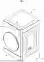


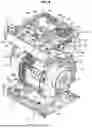
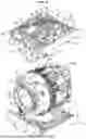
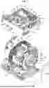
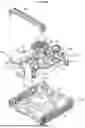


Sources:
- United States Patent and Trademark Office - verify current appl. status at the USPTO↗
Similar patent applications:
- » 20210047773
Apparatus for controlling clothes treating apparatus, clothes treating apparatus and method for controlling clothes treating apparatus - » 20250243616
CLOTHES TREATING APPARATUS AND METHOD FOR CONTROLLING CLOTHES TREATING APPARATUS - » 20260185294
CLOTHES TREATING APPARATUS AND METHOD OF CONTROLLING THE CLOTHES TREATING APPARATUS - » 20240125032
LAUNDRY TREATING APPARATUS AND CONTROL METHOD OF LAUNDRY CLOTHING TREATING APPARATUS - » 20100132129
Clothes treating apparatus and controlling method thereof - » 20110005097
CLOTHES TREATING APPARATUS AND CONTROLLING METHOD THEREOF - » 20090241367
Cloth treating apparatus and controlling method thereof - » 20090241268
Cloth treating apparatus and controlling method thereof - » 20090260254
Clothes treating apparatus and controlling method thereof - » 20110030147
Controlling method of clothes treating apparatus
Recent applications in this class:
- » 20250243616 2025-07-31
CLOTHES TREATING APPARATUS AND METHOD FOR CONTROLLING CLOTHES TREATING APPARATUS - » 20250171943 2025-05-29
LAUNDRY TREATMENT APPLIANCE AND METHOD OF ESTIMATING DRYING TIME BASED ON LAUNDRY LOAD SIZE - » 20250075391 2025-03-06
WASHING MACHINE DRY CYCLE RECOMMENDATIONS - » 20240076822 2024-03-07
WASHING MACHINE ONE-STEP CYCLE DRY TIME ESTIMATION - » 20230160126 2023-05-25
PREDICTION METHOD, RECORDING MEDIUM, PREDICTION SYSTEM, SERVER, AND DISPLAY DEVICE - » 20230111529 2023-04-13
HOME APPLIANCE SYSTEM, MOBILE APPARATUS AND METHOD FOR CONTROLLING HOME APPLIANCES - » 20220275556 2022-09-01
Washing machine and controlling method thereof - » 20210332520 2021-10-28
Control method of a washing machine, and washing machine - » 20210207306 2021-07-08
Artificial intelligence washing machine and operation method thereof - » 20200224350 2020-07-16
Laundry treating apparatus having induction heater and control method thereof
Recent applications for this Assignee:
- » 20260191118 2026-07-02
SEMICONDUCTOR PACKAGE INCLUDING SOLDER BALL STRUCTURE - » 20260191110 2026-07-02
SEMICONDUCTOR PACKAGE AND METHOD OF MANUFACTURING THE SEMICONDUCTOR PACKAGE - » 20260191104 2026-07-02
SEMICONDUCTOR PACKAGE COMPRISING STACKED CHIPS - » 20260191103 2026-07-02
SEMICONDUCTOR DEVICE AND METHOD OF FABRICATING THE SAME - » 20260191101 2026-07-02
PROCESSOR PACKAGE INTEGRATED WITH OPTICAL ENGINE AND METHOD OF MANUFACTURING THE SAME - » 20260191079 2026-07-02
SEMICONDUCTOR PACKAGE AND METHOD OF MANUFACTURING THE SEMICONDUCTOR PACKAGE - » 20260191059 2026-07-02
SEMICONDUCTOR PACKAGE - » 20260191053 2026-07-02
SEMICONDUCTOR PACKAGE - » 20260191021 2026-07-02
SEMICONDUCTOR PACKAGE - » 20260191020 2026-07-02
SEMICONDUCTOR PACKAGE