CLOTHES CARE APPARATUS
US20260185293A1
2026-07-02
19/545,386
2026-02-20
Smart Summary: A clothes care apparatus is designed to help take care of your clothes. It has a special chamber where you can place your clothes for treatment. Inside this chamber, there is a flat heating element that warms up the clothes. This heating element has several layers: one that faces the clothes, a heating layer that produces the heat, a cover layer, and another layer on top. Together, these layers work to ensure the clothes are heated evenly for better care. 🚀 TL;DR
Abstract:
A clothes care apparatus includes a care chamber that accommodates clothes, and a planar heating element that transfers heat to the clothes accommodated in the care chamber. The planar heating element includes a first layer facing the clothes accommodated in the care chamber, a heating layer arranged in contact with the first layer and that generates heat, a cover layer covering the heating layer, and a second layer arranged in contact with the cover layer.
Inventors:
- Minkyung LEE 85 🇰🇷 Suwon-si, South Korea
- Sungmin CHO 18 🇰🇷 Suwon-si, South Korea
- Kwangjoo KIM 34 🇰🇷 Suwon-si, South Korea
- Hoon WEE 6 🇰🇷 Suwon-si, South Korea
- Youngdeog KOH 38 🇰🇷 Suwon-si, South Korea
- JUNHAN BAE 8 🇰🇷 Suwon-si, South Korea
- Soobin KWON 3 🇰🇷 Suwon-si, South Korea
Assignee:
- SAMSUNG ELECTRONICS CO., LTD. 96,505 🇰🇷 Suwon-si, South Korea
Applicant:
Interested in similar patents?
Get notified when new applications in this technology area are published.
Classification:
D06F58/26 » CPC main
Domestic laundry dryers; General details of domestic laundry dryers Heating arrangements, e.g. gas heating equipment
D06F58/10 » CPC further
Domestic laundry dryers Drying cabinets or drying chambers having heating or ventilating means
D06F58/16 » CPC further
Domestic laundry dryers having heatable surfaces for contacting the laundry
D06F67/005 » CPC further
Details of ironing machines provided for in groups , , or Stands or cabinets
D06F67/00 IPC
Details of ironing machines provided for in groups , , or
Description
CROSS-REFERENCE TO RELATED APPLICATION(S)
This application is a continuation of International Application No. PCT/KR2024/011711, filed on Aug. 7, 2024, which is based on and claims priority to Korean Patent Application No. 10-2023-0131104, filed on Sep. 27, 2023, in the Korean Ministry of Intellectual Property, the disclosures of which are incorporated by reference herein in their entireties.
BACKGROUND
1. Field
The present disclosure relates to a clothes care apparatus with an improved heating structure.
2. Description of Related Art
A clothes care apparatus is a device that performs clothes care such as drying wet clothes, removing dust attached to clothes or odors absorbed in clothes, and reducing wrinkles in clothes.
The clothes care apparatus may include, for drying clothes, a condenser that heats a care chamber in which clothes are accommodated or supplies hot air to the care chamber, and may include a steam generating device configured to perform refresh functions such as wrinkle removal, deodorization, and static electricity removal for clothes.
The clothes care apparatus may include a main body forming a care chamber for storing clothes. A machine room in which a steam generating device, a condenser, an evaporator, and the like are arranged may be disposed below the care chamber. The care chamber and the machine room may be separated from each other.
Since the condenser, a compressor, and the like that supply hot air are arranged in the machine room, increasing a capacity of hot air may require an increasing volumes of components such as the compressor and the condenser. As a result, the area of the machine room increases, thereby increasing the overall volume of the clothes care apparatus.
SUMMARY
Provided is a clothes care apparatus capable of heating clothes using a planar heating element.
According to an aspect of the disclosure, there is provided a clothes care apparatus including: a care chamber configured to accommodate clothes; and a planar heating element configured to transfer heat to the clothes accommodated in the care chamber, wherein the planar heating element includes: a first layer configured to face the clothes accommodated in the care chamber, a heating layer arranged in contact with the first layer and configured to generate heat, a cover layer covering the heating layer, and a second layer arranged in contact with the cover layer.
The clothes care apparatus may include a drum connected to one end of the planar heating element and configured to rotate such that the planar heating element is rolled, and a driving motor configured to provide rotational force to the drum.
The planar heating element may be configured to: be wound around the drum by rotation of the drum in a first rotational direction and to be unwound from the drum by rotation of the drum in a second rotational direction opposite to the first direction, and based on the drum being rotated in the second rotational direction, be deployed downward from the drum in the care chamber.
The clothes care apparatus may include a housing to which the drum is rotatably coupled and by which the driving motor is supported, wherein the planar heating element may be configured to, based on the drum being rotated in the first rotational direction, be wound around the drum such that an entirety of the planar heating element is positioned inside the housing.
The planar heating element may be configured to, based on the drum being rotated in the second rotational direction, be unwound from the drum and deployed to an area outside the housing.
The clothes care apparatus may include a clothes support member coupled to an upper surface of the care chamber and configured to support the clothes accommodated in the care chamber, wherein the first layer may be configured to face the clothes support member based on the planar heating element being deployed by rotation of the drum.
The clothes support member may be configured to extend in a first direction, and the drum may include a rotation shaft extending in the first direction, and the drum may be disposed parallel to the clothes support member in a second direction perpendicular to the first direction.
The clothes care apparatus may include a clothes support member coupled to an upper surface of the care chamber and configured to support the clothes accommodated in the care chamber, wherein the drum may be coupled to the clothes support member to be rotatable at a lower side of the clothes support member.
The planar heating element may be on a lower surface of the care chamber, and the first layer may face an upper surface of the care chamber.
The planar heating element may include electrodes electrically connected to the heating layer, and the electrodes are on opposite side ends of the heating layer along a direction in which the planar heating element is unwound by the drum.
The planar heating element may include a sealing member between the first layer and the second layer and configured to seal the heating layer and the cover layer.
The heating layer may include graphene.
The cover layer may include a silicone material.
Each of the first layer and the second layer may include a polyimide film material.
The second layer may include a low-emissivity surface disposed to face the heating layer and configured to reflect heat toward the heating layer.
According to an aspect of the disclosure, a clothes care apparatus includes: a care chamber configured to accommodate clothes; and a heating device configured to transfer heat to the clothes accommodated in the care chamber, wherein the heating device includes: a drum connected to one end of the planar heating element and configured to rotate such that the planar heating element is rolled; and a driving motor configured to provide rotational force to the drum, and the planar heating element is configured to face the clothes accommodated in the care chamber based on the planar heating element being deployed by rotation of the drum.
The planar heating element may include: a first layer configured to face the clothes accommodated in the care chamber; a heating layer in contact with the first layer and configured to generate heat; a cover layer covering the heating layer; and a second layer in contact with the cover layer.
The planar heating element may be configured to: be wound around the drum by rotation of the drum in a first rotational direction and to be unwound from the drum by rotation of the drum in a second rotational direction opposite to the first rotational direction, and based on the drum is rotated in the second rotational direction, be deployed downward from the drum in the care chamber.
The clothes care apparatus may further include a housing to which the drum is rotatably coupled and by which the driving motor is supported, and the planar heating element may be configured to, based on the drum being rotated in the first direction, be wound around the drum such that an entirety of the planar heating element is positioned inside the housing.
The planar heating element may be configured to, based on the drum being rotated in the second rotational direction, be unwound from the drum and deployed to an area outside the housing.
The technical objectives of the present disclosure are not limited to the above, and other objectives that are not described above will be clearly understood by those skilled in the art from the above detailed description.
One or more embodiments of the present disclosure provides a clothes care apparatus that may increase heating efficiency for clothes and remove wrinkles from clothes using a planar heating element.
BRIEF DESCRIPTION OF THE DRAWINGS
The above and other aspects and/or features of embodiments of the disclosure will become more apparent from the following detailed description taken in conjunction with the accompanying drawings, in which:
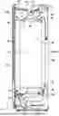
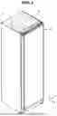
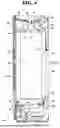
FIG. 1 is a perspective view illustrating a clothes care apparatus according to an embodiment;
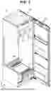
FIG. 2 is a view illustrating a clothes care apparatus according to an embodiment with a door opened;
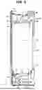
FIG. 3 is a schematic side cross-sectional view illustrating a clothes care apparatus according to an embodiment;
FIG. 4 is a view illustrating a state in which a planar heating element shown in FIG. 3 is deployed;
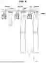
FIG. 5 is a side cross-sectional view schematically illustrating a clothes support member and a heating device of a clothes care apparatus according to an embodiment;
FIG. 6 is a view illustrating a state in which a planar heating element shown in FIG. 5 is deployed;
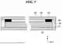
FIG. 7 is a schematic cross-sectional side view of a planar heating element of a clothes care apparatus according to an embodiment;
FIG. 8 is a side cross-sectional view schematically illustrating a clothes support member and a heating device of a clothes care apparatus according to an embodiment;
FIG. 9 is a schematic cross-sectional side view of a planar heating element of a clothes care apparatus according to an embodiment;
FIG. 10 is a view illustrating a clothes care apparatus according to an embodiment with a door opened;
FIG. 11 is a schematic side cross-sectional view of a clothes care apparatus according to an embodiment;
FIG. 12 is a side cross-sectional view schematically illustrating a clothes support member and a heating device of a clothes care apparatus according to an embodiment;
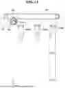
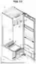
FIG. 13 is a view illustrating the heating device in FIG. 12 in a moved state;
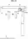
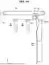
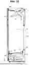
FIG. 14 is a view illustrating a state in which the planar heating element in FIG. 12 is deployed;
FIG. 15 is a view illustrating a clothes care apparatus according to an embodiment with a door opened;
FIG. 16 is a schematic cross-sectional side view illustrating a clothes care apparatus according to an embodiment;
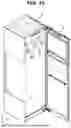
FIG. 17 is a view illustrating a clothes care apparatus according to an embodiment with a door opened;
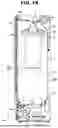
FIG. 18 is a schematic cross-sectional side view illustrating a clothes care apparatus according to an embodiment;
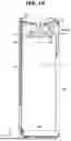
FIG. 19 is a view illustrating a state in which the planar heating element shown in FIG. 18 is deployed;
FIG. 20 is a view illustrating a clothes care apparatus according to an embodiment with a door opened; and
FIG. 21 is a schematic cross-sectional side view illustrating a clothes care apparatus according to an embodiment.
DETAILED DESCRIPTION
The various embodiments of the disclosure and terminology used herein are not intended to limit the technical features of the disclosure to the specific embodiments, but rather should be understood to cover all modifications, equivalents, and alternatives falling within the concept and scope of the disclosure.
In the description of the drawings, like numbers refer to like elements throughout the description of the drawings.
The singular forms preceded by “a,” “an,” and “the” corresponding to an item are intended to include the plural forms as well unless the context clearly indicates otherwise.
In the disclosure, a phrase such as “A or B,” “at least one of A and B,” “at least one of A or B,” “A, B or C,” “at least one of A, B and C,” and “at least one of A, B, or C” may include any one of the items listed together in the corresponding phrase of the phrases, or any possible combination thereof.
The term “and/or” includes combinations of one or all of a plurality of associated listed items.
As used herein, such terms as “1st” and “2nd,” or “first” and “second” may be used to simply distinguish a corresponding component from another, and does not limit the components in other aspect (for example., importance or order).
When one (e.g., a first) element is referred to as being “coupled” or “connected” to another (e.g., a second element with or without the term “functionally” or “communicatively,” it means that the one element is connected to the other element directly, wirelessly, or via a third element.
It will be understood that the terms “include”, “comprise” and/or “have” when used in this specification, specify the presence of stated features, integers, steps, operations, elements, and/or components, but do not preclude the presence or addition of one or more other features, integers, steps, operations, elements, components, and/or groups thereof.
It is to be understood that if a certain component is referred to as being “coupled with,” “coupled to,” “supported on” or “in contact with” another component, it means that the component may be coupled with the other component directly or indirectly via a third component.
Throughout the specification, when a member is referred to as being “on” another member, the member is in contact with another member or yet another member is interposed between the two members.
The terms “front-rear direction,” “left-right direction,” “vertical direction,” “front,” “rear,” “upper,” and “lower” used in the following description are defined based on the drawings, and the shape and position of each element are not limited by the terms.
FIG. 1 is a perspective view illustrating a clothes care apparatus according to an embodiment. FIG. 2 is a view illustrating a clothes care apparatus according to an embodiment with a door opened. FIG. 3 is a schematic side cross-sectional view illustrating a clothes care apparatus according to an embodiment.
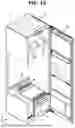
Referring to FIGS. 1 and 2, a clothes care apparatus 1 may include a main body 10 forming an exterior appearance and a door 20 rotatably coupled to the main body 10.
The main body 10 may be provided in the form of a rectangular parallelepiped with an open front surface. The door 20 may be rotatably coupled to the main body 10 and configured to open and close the open front surface of the main body 10.
The main body 10 may include a care chamber 30 provided inside the main body 10 and configured to accommodate and care for clothes. The door 20 may open and close the care chamber 30 by opening and closing the open front surface of the main body 10.
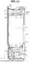
Referring to FIG. 3, the main body 10 may include a machine room 40 partitioned from the care chamber 30 and positioned below the care chamber 30.
As an example, the clothes care apparatus 1 may include a steam generating device 50 that generates steam. The steam generating device 50 may be disposed inside the machine room 40.
As an example, the clothes care apparatus 1 may include a machine room duct 60 configured to blow air into the care chamber 30 and disposed inside the machine room 40.
As an example, the clothes care apparatus 1 may include a machine room fan 61 connected to the machine room duct 60 and configured to blow air into the care chamber 30 through the machine room duct 60.
As an example, the care chamber 30 may include a machine room inlet 31 and a machine room outlet 32 that are connected to the machine room duct 60.
As an example, the care chamber 30 may include a steam inlet 33 connected to the steam generating device 50.
As an example, air inside the care chamber 30 may flow to the machine room duct 60 through the machine room inlet 31 and flow back to the care chamber 30 through the machine room outlet 32.
As an example, a compressor or a condenser may be disposed inside the machine room duct 60 so as to dehumidify or heat air flowing into the care chamber 30.
As an example, the clothes care apparatus 1 may include a drain tank 11 and a water supply tank 12 that are detachably provided from the main body 10.
As an example, the drain tank 11 and the water supply tank 12 may be disposed in a lower portion of the main body 10. As an example, the drain tank 11 and the water supply tank 12 may be disposed in the machine room.
As an example, the drain tank 11 may be configured to facilitate treatment of condensed water generated during an operation of the clothes care apparatus 1.
As an example, the water supply tank 12 may store water required for generating steam in the steam generating device 50.
Water in the water supply tank 12 may be supplied to the steam generating device 50 and used to form steam. The water supply tank 12 may be detachably installed from the main body 10 to facilitate replenishment of water.
As an example, the drain tank 11 and the water supply tank 12 may be provided at a front side of the machine room 40. The machine room 40 may be provided in a lower portion of the main body 10. The machine room 40 may be provided below the care chamber 30.
As an example, the steam generating device 50 that receives water from the water supply tank 12 to generate steam may be disposed in the machine room 40.
The steam generating device 50 may be connected to the water supply tank 12 to receive water and generate steam.
Steam generated by the steam generating device 50 may be moved to the steam inlet 33 and injected into the care chamber 30.
As an example, the steam inlet 33 may be disposed on a rear surface 30b of the care chamber 30 adjacent to a lower surface 30a of the care chamber 30.
As an example, the steam inlet 33 may be disposed on the lower surface 30a of the care chamber 30.
As an example, the steam inlet 33 may be disposed on a side surface of the care chamber 30 adjacent to the lower surface 30a of the care chamber 30.
As an example, a nozzle may be formed at the steam inlet 33 to smoothly inject steam into an inner space of the care chamber 30.
The clothes care apparatus 1 may include a clothes support member 80 provided inside the care chamber 30 and configured to support clothes.
The clothes support member 80 may be installed on an upper surface 30c of the care chamber 30. The clothes support member 80 may be detachably installed in the care chamber 30.
As an example, the clothes support member 80 may be provided as at least one clothes support member 80. The clothes support member 80 may be formed in the shape of a hanger such that clothes may be fitted thereon.
The clothes support member 80 may be configured to allow air to be introduced to the inside thereof. Dust or foreign substances on the clothes may be removed by the air supplied to the inside of the clothes support member 80.
The clothes support member 80 may be provided with an air hole 81 for introducing air into the clothes support member 80. The air hole 81 may be formed at an upper end of the clothes support member 80, and air may be supplied to the clothes through the air hole 81.
As an example, the clothes care apparatus 1 may include a blowing device 90 for circulating air inside the care chamber 30. According to an embodiment, the blowing device 90 may be disposed at an upper side of the care chamber 30.
As an example, the blowing device 90 may be configured to draw in air within the care chamber 30 and supply the air to the clothes support member 80 through the air hole 81.
The clothes care apparatus 1 may include a heating device 100 that transfers heat to clothes supported by the clothes support member 80.
As an example, the heating device 100 may be installed on the upper surface 30c of the care chamber 30.
As an example, the heating device 100 may be arranged parallel to the clothes support member 80 in the left-right direction Y of the main body 10.
As an example, when the clothes support member 80 is provided as a plurality of clothes support members 80, the heating device 100 may be provided corresponding in number to the number of the clothes support members 80. As an example, the plurality of heating devices 100 may each be arranged to correspond to a respective one of the clothes support members 80 in the left-right direction Y with respect to the plurality of clothes support members 80.
The heating device 100 may be configured to transfer heat to clothes by radiating heat generated by the heating device 100 or by conducting heat to clothes in contact with the heating device 100.
Hereinafter, the heating device 100 will be described in detail.
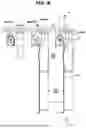
FIG. 4 is a view illustrating a state in which a planar heating element shown in FIG. 3 is deployed, FIG. 5 is a side cross-sectional view schematically illustrating a clothes support member and a heating device of a clothes care apparatus according to an embodiment, FIG. 6 is a view illustrating a state in which a planar heating element shown in FIG. 5 is deployed, and FIG. 7 is a schematic cross-sectional side view of a planar heating element of a clothes care apparatus according to an embodiment.
Referring to FIGS. 4 to 6, the heating device 100 may include a planar heating element 110 configured to generate heat. The planar heating element 110 may be configured to transfer heat to clothes C accommodated inside the care chamber 30 by heat generation.
The heating device 100 may be electrically connected to a power supply unit of the clothes care apparatus 1 and configured to generate heat according to the flow of current.
As an example, the heating device 100 may be formed of a flexible material and configured to be rolled or curved by external force.
As an example, the heating device 100 may include a drum 120 connected to a first end 111 of the planar heating element 110 and configured to rotate such that the planar heating element 110 is rolled.
As an example, the heating device 100 may include a driving motor 130 that transmits rotational force to the drum 12.
The planar heating element 110 may be configured to be wound around the drum 120 by rotation of the drum 120 in one direction and rolled, and to be unwound from the drum 120 by rotation of the drum 120 in the opposite direction.
As an example, when the drum 120 is rotated in the opposite direction, the planar heating element 110 may be configured to be unrolled from the drum 120 and deployed toward the lower surface 30a of the care chamber 30.
As an example, the heating device 100 may include a housing 140 to which the drum 120 is rotatably coupled and on which the driving motor 130 is supported.
As an example, the heating device 100 may be installed on the upper surface 30c of the care chamber 30. As an example, when the planar heating element 110 is unwound by rotation of the drum 120, the planar heating element 110 may be configured to be deployed from a side of the upper surface 30c of the care chamber 30 toward the lower surface 30a of the care chamber 30.
Assuming that a state of the planar heating element 110, in which the second end 112 provided at a position opposite to the first end 111 of the planar heating element 110 is positioned inside the housing 140 by the planar heating element 110 being wound around the drum 120 is a stored state 110i, and a state of the planar heating element 110, in which the second end 112 is drawn out of the housing 140, is a drawn-out state 110o, the planar heating element 110 may be rolled in one direction to switch from the stored state 110i to the drawn-out state 110o, and may be rolled back in the opposite direction to switch from the drawn-out state 110o to the stored state 110i.
Here, the stored state 110i is assumed to be a state in which the planar heating element 110 is completely wound around the drum 120 by rotation of the drum 120, and the drawn-out state is assumed to be a state in which the planar heating element 110 is completely unwound from the drum 120 by rotation of the drum 120 in the opposite direction.
When the planar heating element 110 is in the drawn-out state 110o, the planar heating element 110 may be arranged to face the clothes C positioned inside the care chamber 30.
As an example, a control unit of the clothes care apparatus 1 may control the clothes care apparatus 1 such that voltage is applied to the planar heating element 110 when the planar heating element 110 is in the drawn-out state 110o, thereby allowing the planar heating element 110 to generate heat.
As an example, the control unit of the clothes care apparatus 1 may control the clothes care apparatus 1 such that voltage is not applied to the planar heating element 110 when the planar heating element 110 is in the stored state 110i.
As an example, the clothes support member 80 may be configured to extend in the front-rear direction X. As an example, the clothes support member 80 may support clothes C such that a shoulder line of the clothes C is positioned in the front-rear direction X.
As an example, the drum 120 may include a rotation shaft 121 extending in the front-rear direction X, which is a direction corresponding to the extension direction of the clothes support member 80. As an example, the drum 120 may be provided in a cylindrical shape extending in the front-rear direction X.
As an example, the heating device 100 may be arranged parallel to the clothes support member 80 in the left-right direction Y perpendicular to the extension direction of the clothes support member 80.
When the planar heating element 110 is in the drawn-out state 110o, the planar heating element 110 may be configured to face the clothes support member 80. Accordingly, when the planar heating element 110 is heated, the planar heating element 110 may transfer the heat to the clothes C supported by the clothes support member 80.
The planar heating element 110 includes a heating surface 113 that transfers heat to the clothes C, and when the planar heating element 110 is in the drawn-out state 110o, the heating surface 113 may be configured to face the clothes support member 80. The heating surface 113 may be arranged to face the clothes support member 80 in the left-right direction Y when the planar heating element 110 is in the drawn-out state 110o.
As an example, when the clothes support member 80 is provided as a plurality of clothes support members, each of the plurality of heating devices 100 may be arranged parallel to a respective one of the clothes support members 80 in the left-right direction Y.
As an example, when the clothes support member 80 includes three clothes support members 80, the clothes support member 80 may include a first support member 80a, a second support member 80b, and a third support member 80c arranged in the left-right direction Y. In this case, the heating device 100 may include a first heating device 100a, a second heating device 100b, and a third heating device 100c.
As an example, the first heating device 100a may be arranged to correspond to the first support member 80a in the left-right direction Y. As an example, the second heating device 100b may be arranged to correspond to the second support member 80b in the left-right direction Y. As an example, the third heating device 100c may be arranged to correspond to the third support member 80c in the left-right direction Y.
As an example, when clothes C are supported only on the first support member 80a and the second support member 80b inside the care chamber 30 and no clothes are supported on the third support member 80c, a sensor unit of the clothes care apparatus 1 may sense that clothes C are supported only on the first and second support members 80a and 80b and transmit a sensing value to the control unit of the clothes care apparatus 1. Based on the sensing value, the control unit may control the first heating device 100a and the second heating device 100b such that the planar heating elements 110 of the first heating device 100a and the second heating device 100b switch from the stored state 110i to the drawn-out state 110o. Thereafter, the control unit may control the first heating device 100a and the second heating device 100b such that the planar heating elements 110 of the first heating device 100a and the second heating device 100b generate heat. In this case, the control unit may control the third heating device 100c such that the third heating device 100c is not operated.
n the conventional technology, components, such as a compressor, a heat exchanger and the like configured to heat air for drying clothes, are required, and such components configured to heat air may increase the volume of the machine room, thereby increasing the volume of the clothes care apparatus.
In addition, since high-temperature air is supplied from a high-temperature air supply unit disposed at one side of the care chamber to the interior of the care chamber, the heating efficiency of clothes spaced apart from the supply unit may be reduced, thereby reducing the heating efficiency of the clothes stored in the care chamber.
However, the clothes care apparatus 1 may operate the heating device 100 to dry clothes C accommodated inside the care chamber 30. Since the heating device 100 is disposed adjacent to the clothes C, heat generated from the planar heating element 110 of the heating device 100 is directly transferred, thereby increasing the heating efficiency of the clothes C. In addition, since the heating device 100 is installed inside the care chamber 30, the volume of the machine room 40 may be minimized, thereby minimizing the overall volume of the clothes care apparatus 1 or maximizing the volume of the care chamber 30.
As an example, a distance d1 between the rotation shaft of the drum 120 and a center m of the clothes support member 80 in the left-right direction Y may be set to a distance at which heat generated from the planar heating element 110 may be efficiently transferred to the clothes C supported by the clothes support member 80. As an example, the distance d1 between the rotation shaft of the drum 120 and the center m of the clothes support member 80 may be determined in consideration of the maximum temperature that may be generated from the planar heating element 110, the radiant heat that may be transferred to the clothes C supported by the support member 80, the humidity inside the care chamber 30, and the like.
As an example, the clothes care apparatus 1 may be configured such that steam generated by the steam generating device 50 is injected into the care chamber 30 to perform refresh functions such as wrinkle removal, deodorization, and static electricity removal for clothes C disposed inside the care chamber 30.
In the clothes care apparatus according to the conventional technology, after steam is injected into the care chamber, hot air is supplied into the care chamber such that wrinkles in the clothes are removed while moisture on the clothes is being dried. However, in the drying of clothes with hot air, the wrinkle removal is not efficient. In addition, since an excessive amount of steam is generated to remove wrinkles, a steam generation time increases, and the power supplied to the clothes care apparatus to generate excessive steam increases.
However, the heating device 100 of the clothes care apparatus 1 is disposed adjacent to the clothes C, and heat generated directly from the planar heating element 110 of the heating device 100 is directly transferred, thereby increasing heating efficiency of the clothes C. In addition, since the heating device 100 is installed inside the care chamber 30, the volume of the machine room 40 may be minimized, thereby minimizing the overall volume of the clothes care apparatus 1 or maximizing the volume of the care chamber 30.
In addition, since the heating device 100 directly transfers heat generated by the heating device 100 to the clothes C, the refresh function of the clothes care apparatus 1 may be performed with a smaller amount of steam than in the conventional technology.
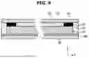
Referring to FIG. 7, the planar heating element 110 may include a first layer 114 forming a heating surface 113.
The first layer 114 may be provided as a layer closest to the clothes support member 80 in the left-right direction Y.
The heating surface 113 is a surface exposed to the outside in the first layer 114 and may be configured to discharge heat generated from the planar heating element 110 to the outside.
The heating surface 113 may be provided to receive heat generated from a heating layer 115, which will be described below, and to radiate the generated heat to the clothes C supported by the clothes support member 80.
As an example, the first layer 114 may be formed of a transparent material.
As an example, the first layer 114 may be formed of a flexible material.
As an example, the first layer 114 may be formed of polyimide film material.
As an example, the first layer 114 may be formed of ultra-thin glass (UTG) material.
The planar heating element 110 may be formed of a material having a predetermined transparency such that the user may check the state of the clothes C accommodated inside the care chamber 30 even when in the drawn-out state 100o.
Accordingly, not only the first layer 114 but also the heating layer 115, electrode 116, a cover layer 117, and a second layer 118, which will be described below, may also be formed of a material having a predetermined transparency.
As an example, the first layer 114 may be provided in a quadrangular shape.
The planar heating element 110 may include a heating layer 115 disposed behind the first layer 114 with respect to the clothes support member 80 in the left-right direction Y and configured to generate heat.
As an example, the heating layer 115 may be formed of a flexible material.
As an example, the heating layer 115 may be formed of graphene material. As an example, the heating layer 115 may be provided as a graphene thin film layer.
The heating layer 115 may be connected to a power supply unit located outside the heating layer 115 through the electrode 116, which will be described below and configured to generate heat by current as power is applied.
As an example, the heating layer 115 may be formed of transparent graphene material.
As an example, the heating layer 115 may be provided in a quadrangular shape. As an example, the heating layer 115 may be provided in a quadrangular shape with a smaller area than that of the first layer 114.
As an example, the heating layer 115 may include a plurality of graphene thin film layers. As an example, the plurality of graphene thin film layers may be arranged to overlap each other in the left-right direction Y when the planar heating element 110 is in the drawn-out state 110o.
A sheet resistance value of the heating layer 115 as a whole may be set through the number of plurality of graphene thin film layers, and accordingly, the temperature level of heat transferred to the clothes C supported by the clothes support member 80 may be set.
As an example, the plurality of graphene thin film layers may be configured to be stacked in a number of two or three layers in the left-right direction Y. As an example, the plurality of graphene thin film layers may be configured to be stacked in a number of ten or fewer layers in the left-right direction Y.
As an example, the planar heating element 110 may include electrodes 116 electrically connected to the heating layer 115.
As an example, the electrodes 116 may be respectively provided on a pair of edges of the heating layer 115, which is formed in a quadrangular shape.
As an example, the electrodes 116 may be provided to extend along long sides of the heating layer 115 corresponding to long sides 110L) of the planar heating element 110.
This is to shorten the distance between the pair of electrodes 116. When the pair of electrodes 116 extends along short sides of the heating layer 115 corresponding to short sides 120b of the planar heating element 110, the distance between the pair of electrodes 116 become greater than when the electrodes extend along the long sides of the heating layer 115, which may reduce heating performance.
As an example, the electrodes 116 may be formed by patterning. As an example, the electrodes 116 may be provided to be patterned on the edges of the heating layer 115. As an example, a pattern structure may be formed on the edges of the heating layer 115, and the electrodes 116 may be provided by being transferred to the pattern structure.
As an example, the electrodes 116 may include a transparent material to have a predetermined transparency. As an example, the electrode 116 may include metal materials such as silver (Ag) or copper (Cu) for conductivity and a material having a transparent material.
As an example, the electrodes 116 may be provided with a fine-sized pattern so as not to be visible to the user.
The planar heating element 110 may include a cover layer 117 that covers the heating layer 115 from behind the heating layer 115 when the planar heating element 110 is in the drawn-out state 110o.
As an example, the cover layer 117 may be formed of a flexible material.
As an example, the cover layer 117 may be formed of a transparent material.
The cover layer 117 may prevent the heating layer 115 from being exposed to the outside, thereby preventing the heating layer 115 from being oxidized by contact with external air.
A front surface of the heating layer 115 and a rear surface of the heating layer 115 may be covered by the first layer 114 and the cover layer 117 so as not to be exposed to the outside.
The front surface of the heating layer 115 may be attached to an upper surface of the first layer 114 and the rear surface of the heating layer 115 may be bonded to the cover layer 117.
As an example, the cover layer 117 may be formed of a material with high heat resistance.
As an example, the cover layer 117 may be formed of a polymer material with high airtightness.
As an example, the cover layer 117 may include silicone material. As an example, the cover layer 117 may include ethylene vinyl acetate (EVA) material.
The planar heating element 110 may include a second layer 118 formed at a rear end of the planar heating element 110 in the left-right direction Y when the planar heating element 110 is in the drawn-out state 110o.
The second layer 118 may be disposed behind the cover layer 117 in the left-right direction Y.
As an example, the second layer 118 may be formed of a transparent material.
As an example, the second layer 118 may be formed of a flexible material. As an example, the second layer 119 may be formed of polyimide film material.
As an example, the second layer 118 may be formed of ultra-thin glass (UTG) material.
As an example, the second layer 118 may be provided in a quadrangular shape. As an example, the second layer 118 may be formed with an area approximately corresponding to that of the first layer 114. As an example, the second layer 118 and the first layer 114 may be arranged to overlap each other.
The planar heating element 110 may include a sealing member 119 that is disposed between the first layer 114 and the second layer 118 in the left-right direction Y when the planar heating element 110 is in the drawn-out state 110o and seals the heating layer 115 and the cover layer 117.
The sealing member 119 may prevent external air from flowing into the planar heating element 110 in the front-rear direction X or the up-down direction Z.
The sealing member 119 may be configured to seal the edges of the planar heating element 110. As an example, the sealing member 119 may be configured to seal between the first layer 114 and the second layer 118 in the up-down direction Z and the front-rear direction X.
As an example, the sealing member 119 may be formed of a polymer material with high airtightness.
As an example, the sealing member 19 may include acrylic material or silicone material.
As an example, the planar heating element 110 may be provided to have a thickness less than or equal to a predetermined thickness to maintain a state of being wound around the drum 120 by rotation of the drum 120. As an example, the planar heating element 110 may be provided to have a thickness of 1 mm or less.
FIG. 8 is a side cross-sectional view schematically illustrating a clothes support member and a heating device of a clothes care apparatus according to an embodiment.
In the conventional technology, since an excessive amount of steam is generated to remove wrinkles, a steam generation time increases, and the power supplied to the clothes care apparatus to generate excessive steam increases.
As an example, a distance d2 between the rotation shaft of the drum 120 and a center m of the clothes support member 80 in the left-right direction Y may be set such that wrinkles are removed from the clothes C as the planar heating element 110 is heated while the clothes C supported by the clothes support member 80 are in direct contact with the heating device 100 of the clothes care apparatus 1.
As the heated planar heating element 110 is in direct contact with the clothes C, wrinkles may be efficiently removed by the planar heating element 110.
The distance d2 between the rotation shaft of the drum 120 and the center m of the clothes support member 80 in the left-right direction Y may be configured such that a distance between the planar heating element 110 and the clothes C supported by the clothes support member 80 in the left-right direction Y is very small when the planar heating element 110 is in the drawn-out state 110o.
As an example, the planar heating element 110 adjacent to the clothes C may be provided to contact the clothes C by moisture remaining on the clothes C due to steam.
As an example, the distance d2 between the rotation shaft of the drum 120 and the center m of the clothes support member 80 in the left-right direction Y may be provided to be a distance at which the planar heating element 110 may contact the clothes C by moisture remaining on the clothes C due to steam.
As an example, the heating device 100 may be provided to move in the left-right direction Y according to the type of operation of the clothes care apparatus 1.
As an example, the control unit of the clothes care apparatus 1 may control the heating device 100 such that the position of the heating device 100 in the left-right direction Y is moved based on the type of operation input by the user.
As an example, the heating device 100 may be moved in the left-right direction Y such that the distance between the rotation shaft of the drum 120 and the center m of the clothes support member 80 changes in the left-right direction Y.
As an example, when clothes that do not require wrinkle removal are supported on the clothes support member 80, the user may input a clothes care operation that does not include wrinkle removal to the clothes care apparatus 1, and the control unit of the clothes care apparatus 1 may control the position of the heating device 100 such that the distance between the rotation shaft of the drum 120 and the center m of the clothes support member 80 in the left-right direction Y is d1 based on the information input by the user.
As an example, when clothes that require wrinkle removal are supported on the clothes support member 80, the user may input a clothes care operation including wrinkle removal to the clothes care apparatus 1, and the control unit of the clothes care apparatus 1 may control the heating device 100 such that the position of the heating device 100 is moved such that the distance between the rotation shaft of the drum 120 and the center m of the clothes support member 80 in the left-right direction Y changes from d1 to d2 based on the information input by the user.
As an example, when the user inputs an operation in which the first support member 80a requires wrinkle removal and the second support member 80b does not require wrinkle removal, the control unit may control the position of the first heating device 100a such that the distance between the rotation shaft 121 of the drum 120 of the first heating device 100a and the center m of the first support member 80a in the left-right direction Y becomes d2 based on the information input by the user, and may control the position of the second heating device 100b such that the distance between the rotation shaft 121 of the drum 120 of the second heating device 100b and the center m of the second support member 80b in the left-right direction Y becomes d1.
FIG. 9 is a schematic cross-sectional side view of a planar heating element of a clothes care apparatus according to an embodiment.
As an example, the second layer 118 may include a low-emissivity surface 118a disposed to face the heating layer 115 to reflect heat toward the heating layer 115.
As an example, the low-emissivity surface 118a may be formed on a front surface of the second layer 118 when the planar heating element 110 is in the drawn-out state 110o.
As an example, the low-emissivity surface 118a may be provided with a low-emissivity coating having an emissivity approximately between 0.01 and 0.5.
As an example, the low-emissivity surface 118a coated with a low-emissivity material may be disposed on the front surface of the second layer 118.
Heat transferred from the heating layer 115 to the second layer 118 may be reflected back to the heating layer 115 and the heating surface 113 by the low-emissivity surface 118a, such that a greater amount of heat may be transferred from the heating surface 113 to the clothes C supported by the clothes support member 80.
As an example, when the planar heating element 110 is in the drawn-out state 110o, the low-emissivity surface 118a may reflect, among heat generated from the heating layer 115, heat moving in the opposite direction to the direction in which the clothes support member 80 is disposed, thereby increasing the heating efficiency of the planar heating element.
FIG. 10 is a view illustrating a clothes care apparatus according to an embodiment with a door opened. FIG. 11 is a schematic side cross-sectional view of a clothes care apparatus according to an embodiment.
As an example, the clothes care apparatus 1 may include a compressor 62 and heat exchangers 63 and 64 configured to provide heated air into the care chamber 30 or dehumidify air inside the care chamber 30.
As an example, the compressor 62 and the heat exchangers 63 and 64 may be disposed inside the machine room 40.
As an example, the heat exchangers 63 and 64 may be disposed inside the machine room duct 60 to exchange heat with air flowing inside the machine room duct 60. Air that has exchanged heat with the heat exchangers 63 and 64 may flow into the care chamber 30 through the machine room duct 60.
As an example, the heat exchangers 63 and 64 may include an evaporator 63 and a condenser 64.
As an example, air introduced into the machine room duct 60 passes through the evaporator 63, in which a refrigerant evaporates to absorb latent heat from the surrounding air, thereby condensing and removing moisture in the air. The air with moisture removed may be introduced back into the care chamber 30 through the machine room duct 60, thereby dehumidifying air inside the care chamber 30.
As an example, when the refrigerant condenses in the condenser 64 after passing through the compressor 62, latent heat is released to the surrounding air, thereby heating air inside the machine room duct 60.
As an example, as the evaporator 63 and the condenser 64 perform a heat exchange function, the air introduced into the machine room 40 by the machine room fan 61 may be dehumidified and heated by sequentially passing through the evaporator 63 and the condenser 64.
As an example, the machine room duct 60 may be connected to the machine room inlet 31 and the machine room outlet 32 of the care chamber 30. One end of the machine room duct 60 may be connected to the machine room inlet 31 and the other end of the machine room duct 60 may be connected to the machine room outlet 32.
Air in the care chamber 30 may be discharged into the machine room duct 60 through the machine room outlet 32, and the discharged air may be dehumidified and reintroduced into the care chamber 30 through the machine room inlet 31.
As an example, condensed water condensed by the evaporator 51 may be collected in the drain tank 11 and discharged outside the clothes care apparatus 1.
As an example, the clothes care apparatus 1 may include the condenser 64 and the heating device 100 as components for heating the inside of the care chamber 30.
In the conventional technology, in order to heat the inside of the clothes care apparatus, air having heat exchanged by a condenser is introduced into the care chamber. To provide high-temperature heat into the care chamber, the capacities of the compressor and the condenser are increased, which increases the volume inside the machine room. As the high-temperature air is supplied into the care chamber from a high-temperature air supply unit disposed at one side of the care chamber, the heating efficiency of clothes spaced apart from the supply unit is reduced, thereby reducing overall heating efficiency of clothes stored in the care chamber.
However, the clothes care apparatus 1 includes not only the condenser 64 that heats the air inside the care chamber 30 but also the heating device 100 that directly supplies heat to the clothes accommodated inside the care chamber 30, so that the capacities of the compressor 62 and the condenser 64 may be reduced compared to those of conventional compressors and condensers, thereby reducing the volume of the machine room 40 and increasing the heating efficiency of clothes stored in the care chamber 30.
As an example, the control unit of the clothes care apparatus 1 may control the clothes care apparatus 1, based on input information on an operation mode of the clothes care apparatus provided by a user, to selectively operate in one of an operation in which high-temperature air is supplied into the care chamber 30 through the condenser 64, and an operation mode in which heat is directly transferred to clothes accommodated inside the care chamber 30 through the heating device 100.
As an example, the control unit of the clothes care apparatus 1 may control the clothes care apparatus 1, based on input information on an operation mode of the clothes care apparatus 1 provided by the user, to supply high-temperature air into the care chamber 30 through the condenser 64 while simultaneously directly transferring heat to clothes accommodated inside the care chamber 30 through the heating device 100.
As an example, the control unit of the clothes care apparatus 1 may control the clothes care apparatus 1 such that the amount of heat transferred to the clothes accommodated inside the care chamber 30 through the condenser 64 is greater than the amount transferred from the heating device 100 when the condenser 64 and the heating device 100 are operated simultaneously.
As an example, the control unit of the clothes care apparatus 1 may control the clothes care apparatus 1 such that the amount of heat transferred to the clothes accommodated inside the care chamber 30 through the condenser 64 is less than the amount transferred from the heating device 100 when the condenser 64 and the heating device 100 are operated simultaneously.
FIG. 12 is a side cross-sectional view schematically illustrating a clothes support member and a heating device of a clothes care apparatus according to an embodiment. FIG. 13 is a view illustrating the heating device in FIG. 12 in a moved state. FIG. 14 is a view illustrating a state in which the planar heating element in FIG. 12 is deployed.
Referring to FIGS. 12 to 14, as an example, a clothes care apparatus 1 may include a compressor and heat exchangers configured to provide heated air into a care chamber 30 or dehumidify air inside the care chamber 30, and a heating device 200 that directly transfers heat to clothes C accommodated inside the care chamber 30.
As an example, clothes C accommodated inside the care chamber 30 of the clothes care apparatus 1 may be heated by high-temperature air produced from the heat exchanger. As an example, the heating device 200 may additionally provide heat to clothes C accommodated inside the care chamber 30. As an example, when additional heating is required for clothes C supported on one support member 80a among a plurality of clothes support members 80, a planar heating element 210 of the heating device 200 may enter a drawn-out state 210o toward the clothes C supported on the one support member 80a and generate heat.
As an example, when an additional wrinkle removal process is required for clothes C supported on one support member 80a among a plurality of clothes support members 80, the planar heating element 210 of the heating device 200 may enter a drawn-out state 210o toward the clothes C supported on the one support member 80a and generate heat. The planar heating element 210 may be provided to contact the clothes C supported on the one support member 80a in the drawn-out state 210o, and may generate heat while in contact with the clothes C to remove wrinkles from the clothes C.
As an example, the clothes care apparatus 1 may operate the heating device 200 such that the planar heating element 210 enters a drawn-out state 210o and transfers heat to clothes C while the heat exchanger and the compressor are operating.
As an example, the clothes care apparatus 1 may operate the heating device 200 such that the planar heating element 210 enters a drawn-out state 210o and transfers heat to the clothes C after the heat exchanger and the compressor have operated.
As an example, the clothes care apparatus 1 may operate the heating device 200 such that the planar heating element 210 enters a drawn-out state 210o and transfers heat to the clothes C before the heat exchanger and the compressor operate.
As an example, the clothes care apparatus 1 may provide heat to clothes C accommodated inside the care chamber 30 through the heating device 200 in a state in which the compressor and the heat exchanger are not operating. As an example, the heating device 200 may be provided to transfer heat only to clothes C supported on one support member 80a among a plurality of clothes support members 80.
As an example, the heating device 200 may be provided to be movable in the left-right direction Y. As an example, the heating device 200 may include a moving device 290, and the housing 240 of the heating device 200 may be connected to the moving device 290 and provided to move in the left-right direction Y.
As an example, the moving device 290 may include a rail extending in the left-right direction Y, a driving motor, and the like, and may be coupled to the housing 240 to move the housing 240.
As an example, the rail of the moving device 290 may also extend in the front-rear direction X and/or the up-down direction Z, such that the housing 240 may move in the front-rear direction X and/or the up-down direction Z.
As an example, while the housing 240 is moved by the moving device 290, the planar heating element 210, disposed inside the housing 240 in a stored state 210i), may be moved together with the housing 240.
As an example, the moving device 290 may be disposed on the upper surface 30c of the care chamber 30 and positioned outside the care chamber 30.
As an example, the moving device 290 may be installed on the upper surface 30c of the care chamber 30 and positioned inside the care chamber 30.
As an example, a sensor unit of the clothes care apparatus 1 may sense that clothes C are supported only on the first support member 80a and transmit a sensing value to the control unit of the clothes care apparatus 1. Based on the sensing value, the control unit may control the heating device 200 such that the moving device 290 moves the housing 240 to a position adjacent to the first support member 80a in the left-right direction Y. The control unit may control the heating device 200 such that the planar heating element 210 enters a drawn-out state 210o through rotation of the drum 220 after the housing 240 has moved to the position adjacent to the first support member 80a in the left-right direction Y.
As an example, the control unit of the clothes care apparatus 1 may control the heating device 200 such that the housing 240 is moved to a certain position by the moving device 290 based on input information provided by a user. As an example, when clothes C supported on the first support member 80a require additional wrinkle removal, the user may input corresponding information to the clothes care apparatus 1, and based on the input information provided by the user, the control unit may control the heating device 200 such that the housing 240 is moved to a position adjacent to the first support member 80a by the moving device 290 and the planar heating element 210 enters a drawn-out state 210o through rotation of the drum 220.
FIG. 15 is a view illustrating a clothes care apparatus according to an embodiment with a door opened. FIG. 16 is a schematic cross-sectional side view illustrating a clothes care apparatus according to an embodiment.
Referring to FIGS. 15 and 16, as an example, a clothes care apparatus 1 may transfer heat into a care chamber 30 only through a heating device 100.
As an example, the clothes care apparatus 1 may circulate air inside the care chamber 30 through a blowing device 90.
As an example, since components such as a compressor, heat exchangers, a machine room duct and the like for supplying high-temperature air into the care chamber 30 are not required in the clothes care apparatus 1, the volume of the care chamber 30 may be maximized, thereby increasing the volume of clothes that may be accommodated inside the care chamber 30.
As an example, as the volume of the care chamber 30 of the clothes care apparatus 1 increases, an additional care module for caring for clothes and miscellaneous items may be installed at one side of the care chamber 30. As an example, a care module for caring for shoes and the like may be installed at a lower portion of the care chamber 30.
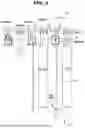
FIG. 17 is a view illustrating a clothes care apparatus according to an embodiment with a door opened. FIG. 18 is a schematic cross-sectional side view illustrating a clothes care apparatus according to an embodiment. FIG. 19 is a view illustrating a state in which the planar heating element shown in FIG. 18 is deployed.
Referring to FIGS. 17 to 19, as an example, a heating device 300 may be disposed below a clothes support member 80.
As an example, a clothes care apparatus 1 may include a compressor and heat exchangers configured to provide heated air into a care chamber 30 or dehumidify air inside the care chamber 30, and a heating device 300 that directly transfers heat to clothes C accommodated inside the care chamber 30.
As an example, the clothes care apparatus 1 may include the heating device 300 to heat the inside of the care chamber 30.
As an example, a housing 340 may be connected to a clothes support member 80 at a lower side of the clothes support member 80.
As an example, the housing 340 may be disposed inside clothes C when the clothes C is supported on the clothes support member 80.
As an example, the heating device 300 may be operated while clothes C are supported on the clothes support member 80. As an example, while the planar heating element 310 is drawn out from the housing 340 to a drawn-out state 310o, the planar heating element 310 may be disposed inside the clothes C.
As an example, when the planar heating element 310 generates heat, the heat is transferred to the clothes C from the inside of the clothes C, thereby increasing the heating efficiency with respect to the clothes C.
As an example, when the planar heating element 310 is disposed inside the clothes C while in the drawn-out state 310o, at least a portion of the clothes C may be provided to contact the planar heating element 310. As an example, when the planar heating element 310 generates heat, the at least a portion of the clothes C in contact with the planar heating element 310 may easily have wrinkles removed by the planar heating element 310.
As an example, a driving motor 330 may rotate the drum 320 such that the planar heating element 310 is rolled.
As an example, the driving motor 330 may be provided to vibrate as rotational force is generated. As an example, a control unit of the clothes care apparatus 1 may control the driving motor 330 such that the driving motor 330 vibrates.
As an example, vibration of the driving motor 330 may be transmitted to the clothes support member 80, and accordingly, vibration may be transmitted to the clothes C supported by the clothes support member 80 such that foreign substances remaining on the clothes C may be separated from the clothes C.
As an example, the heating device 300 may be configured such that vibration is generated in the drum 320 as the driving motor 330 periodically rotates the drum 320.
As an example, vibration of the drum 320 may be transmitted to the clothes support member 80, and accordingly, the vibration may be transmitted to the clothes C supported by the clothes support member 80 such that foreign substances remaining on the clothes C may be separated from the clothes C.
FIG. 20 is a view illustrating a clothes care apparatus according to an embodiment with a door opened. FIG. 21 is a schematic cross-sectional side view illustrating a clothes care apparatus according to an embodiment.
Referring to FIGS. 20 and 21, as an example, a planar heating element 410 may be disposed on a lower surface 30a of a care chamber 30.
As an example, a clothes care apparatus 1 may include a compressor and heat exchangers provided to provide heated air inside the care chamber 30 or dehumidify air inside the care chamber 30, and a planar heating element 410 that directly transfers heat to clothes C accommodated inside the care chamber 30.
As an example, the clothes care apparatus 1 may include the planar heating element 410 to heat the inside of the care chamber 30.
As an example, heat generated from the planar heating element 410 may be transferred to the inside of the care chamber 30 and directly transferred to clothes accommodated inside the care chamber 30.
As an example, the planar heating element 410 may be disposed on a rear surface 30b of the care chamber 30.
As an example, the planar heating element 410 may be disposed on a upper surface 30c of the care chamber 30.
As an example, a clothes care apparatus includes: a care chamber configured to accommodate clothes; and a planar heating element configured to transfer heat to the clothes accommodated in the care chamber, wherein the planar heating element includes: a first layer configured to face the clothes accommodated in the care chamber, a heating layer arranged in contact with the first layer and configured to generate heat, a cover layer covering the heating layer, and a second layer arranged in contact with the cover layer.
As an example, the clothes care apparatus further includes: a drum connected to one end of the planar heating element and configured to rotate such that the planar heating element is rolled, and a driving motor configured to transmit (or provide) rotational force to the drum.
As an example, the planar heating element is configured to be wound around the drum by rotation of the drum in one direction and to be unwound from the drum by rotation of the drum in an opposite direction, and when the drum is rotated in the opposite direction (e.g., based on the drum being rotated in the opposite direction), the planar heating element is configured to be deployed downward from the drum in the care chamber.
As an example, the clothes care apparatus further includes a housing to which the drum is rotatably coupled and by which the driving motor is supported, wherein when the drum is rotated in the one direction, the planar heating element is configured to be wound around the drum such that the entire planar heating element is positioned inside the housing.
As an example, when the drum is rotated in the opposite direction, the planar heating element is configured to be unwound from the drum and deployed to an area outside the housing.
As an example, the clothes care apparatus further includes a clothes support member coupled to an upper surface of the care chamber and configured to support the clothes accommodated in the care chamber, wherein the first layer is configured to face the clothes support member when the planar heating element is deployed by rotation of the drum.
As an example, the clothes support member is configured to extend in one direction, and the drum includes a rotation shaft extending in a direction corresponding to a direction in which the clothes support member extends, and the drum is disposed parallel to the clothes support member in a direction perpendicular to the direction in which the clothes support member extends.
As an example, the clothes care apparatus further includes a clothes support member coupled to an upper surface of the care chamber and configured to support the clothes accommodated in the care chamber, wherein the drum is coupled to the clothes support member to be rotatable at a lower side of the clothes support member.
As an example, the planar heating element is disposed on a lower surface of the care chamber, and the first layer is disposed to face an upper surface of the care chamber.
As an example, the planar heating element further includes electrodes electrically connected to the heating layer, and the electrodes are formed on opposite side ends of the heating layer along a direction in which the planar heating element is unwound by the drum.
As an example, the planar heating element further includes a sealing member disposed between the first layer and the second layer and configured to seal the heating layer and the cover layer.
As an example, the heating layer is formed of graphene.
As an example, the cover layer includes silicone material.
As an example, the first layer and the second layer are each formed of polyimide film material.
As an example, the second layer includes a low-emissivity surface disposed to face the heating layer to reflect heat toward the heating layer.
As an example, a clothes care apparatus includes: a care chamber configured to accommodate clothes; and a heating device configured to transfer heat to the clothes accommodated in the care chamber, wherein the heating device includes a drum connected to one end of the planar heating element and configured to rotate such that the planar heating element is rolled, and a driving motor configured to transmit rotational force to the drum, wherein the planar heating element is configured to face the clothes accommodated in the care chamber when the planar heating element is deployed by rotation of the drum.
As an example, the planar heating element includes: a first layer configured to face the clothes accommodated in the care chamber, a heating layer arranged in contact with the first layer and configured to generate heat, a cover layer covering the heating layer, and a second layer arranged in contact with the cover layer.
As an example, the planar heating element is configured to be wound around the drum by rotation of the drum in one direction and to be unwound from the drum by rotation of the drum in an opposite direction, and when the drum is rotated in the opposite direction, the planar heating element is configured to be deployed downward from the drum in the care chamber.
As an example, the clothes care apparatus further includes a housing to which the drum is rotatably coupled and by which the driving motor is supported, wherein when the drum is rotated in the one direction, the planar heating element is configured to be wound around the drum such that the entire planar heating element is positioned inside the housing.
As an example, when the drum is rotated in the opposite direction, the planar heating element is configured to be unwound from the drum and deployed to an area outside the housing.
Although certain illustrative embodiments and implementations have been described herein, other embodiments and modifications will be apparent from this description. Accordingly, embodiments of the disclosure are not limited to the described embodiments, but rather to the broader scope of the appended claims and various obvious modifications and equivalent arrangements as would be apparent to a person of ordinary skill in the art.
Claims
What is claimed is:1. A clothes care apparatus comprising:
a care chamber configured to accommodate clothes; and
a planar heating element configured to transfer heat to the clothes accommodated in the care chamber,
wherein the planar heating element comprises:
a first layer configured to face the clothes accommodated in the care chamber,
a heating layer in contact with the first layer and configured to generate heat,
a cover layer covering the heating layer, and
a second layer in contact with the cover layer.
2. The clothes care apparatus of claim 1, further comprising:
a drum connected to one end of the planar heating element and configured to rotate such that the planar heating element is rolled, and
a driving motor configured to provide rotational force to the drum.
3. The clothes care apparatus of claim 2, wherein the planar heating element is configured to:
be wound around the drum by rotation of the drum in a first rotational direction and to be unwound from the drum by rotation of the drum in opposite second rotational direction opposite to the first rotational direction, and
based on the drum being rotated in the second rotational direction, be deployed downward from the drum in the care chamber.
4. The clothes care apparatus of claim 3, further comprising a housing to which the drum is rotatably coupled and by which the driving motor is supported,
wherein the planar heating element is configured to, based on the drum being rotated in the first rotational direction, be wound around the drum such that an entirety of the planar heating element is positioned inside the housing.
5. The clothes care apparatus of claim 4, wherein the planar heating element is configured to, based on the drum being rotated in the second rotational direction, be unwound from the drum and deployed to an area outside the housing.
6. The clothes care apparatus of claim 2, further comprising a clothes support member coupled to an upper surface of the care chamber and configured to support the clothes accommodated in the care chamber,
wherein the first layer is configured to face the clothes support member based on the planar heating element being deployed by rotation of the drum.
7. The clothes care apparatus of claim 6, wherein the clothes support member extends in a first direction, and
wherein the drum comprises a rotation shaft extending in the first direction, and the drum is disposed parallel to the clothes support member in a second direction perpendicular to the first direction.
8. The clothes care apparatus of claim 2, further comprising a clothes support member coupled to an upper surface of the care chamber and configured to support the clothes accommodated in the care chamber,
wherein the drum is coupled to the clothes support member to be rotatable at a lower side of the clothes support member.
9. The clothes care apparatus of claim 1, wherein the planar heating element is on a lower surface of the care chamber, and
wherein the first layer faces an upper surface of the care chamber.
10. The clothes care apparatus of claim 3, wherein the planar heating element further comprises electrodes electrically connected to the heating layer, and
wherein the electrodes are on opposite side ends of the heating layer along a direction in which the planar heating element is unwound by the drum.
11. The clothes care apparatus of claim 1, wherein the planar heating element further comprises a sealing member between the first layer and the second layer and configured to seal the heating layer and the cover layer.
12. The clothes care apparatus of claim 1, wherein the heating layer comprises graphene.
13. The clothes care apparatus of claim 1, wherein the cover layer comprises a silicone material.
14. The clothes care apparatus of claim 1, wherein each of the first layer and the second layer comprises a polyimide film material.
15. The clothes care apparatus of claim 1, wherein the second layer comprises a low-emissivity surface facing the heating layer and configured to reflect heat toward the heating layer.
16. A clothes care apparatus comprising:
a care chamber configured to accommodate clothes; and
a heating device configured to transfer heat to the clothes accommodated in the care chamber,
wherein the heating device comprises:
a drum connected to one end of the planar heating element and configured to rotate such that the planar heating element is rolled; and
a driving motor configured to provide rotational force to the drum, and
wherein the planar heating element is configured to face the clothes accommodated in the care chamber based on the planar heating element being deployed by rotation of the drum.
17. The clothes care apparatus of claim 16, wherein the planar heating element comprises:
a first layer configured to face the clothes accommodated in the care chamber;
a heating layer in contact with the first layer and configured to generate heat;
a cover layer covering the heating layer; and
a second layer in contact with the cover layer.
18. The clothes care apparatus of claim of claim 16, wherein the planar heating element is configured to:
be wound around the drum by rotation of the drum in a first rotational direction and to be unwound from the drum by rotation of the drum in a second rotational direction opposite to the first rotational direction, and
based on the drum is rotated in the second rotational direction, be deployed downward from the drum in the care chamber.
19. The clothes care apparatus of claim 18, further comprising a housing to which the drum is rotatably coupled and by which the driving motor is supported,
wherein the planar heating element is configured to, based on the drum being rotated in the first direction, be wound around the drum such that an entirety of the planar heating element is positioned inside the housing.
20. The clothes care apparatus of claim 19, the planar heating element is configured to, based on the drum being rotated in the second rotational direction, be unwound from the drum and deployed to an area outside the housing.
Images & Drawings included:


Sources:
- United States Patent and Trademark Office - verify current appl. status at the USPTO↗
Similar patent applications:
- » 20250066976
CLOTHES CARE APPARATUS AND METHOD FOR CONTROLLING CLOTHES CARE APPARATUS - » 20260185296
CLOTHING CARE APPARATUS AND METHOD FOR CONTROLLING CLOTHING CARE APPARATUS - » 20200071875
Clothes care apparatus and control method thereof - » 20200080254
Clothes care apparatus - » 20200385916
Iron device, clothes care apparatus and control method thereof - » 20200385917
Clothes care apparatus - » 20210017690
CLOTHES CARE APPARATUS AND CONTROL METHOD THEREOF - » 20200392664
Clothes care apparatus - » 20210017699
Clothes care apparatus and control method thereof - » 20200080250
Clothes care apparatus
Recent applications in this class:
- » 20260185292 2026-07-02
CLOTHES TREATING APPARATUS - » 20260185291 2026-07-02
CLOTHES TREATING APPARATUS - » 20260160014 2026-06-11
CLOTHES TREATING APPARATUS - » 20260152898 2026-06-04
LAUNDRY TREATING APPARATUS AND METHOD FOR CONTROLLING THE SAME - » 20260125845 2026-05-07
CLOTHES DRYER - » 20250277333 2025-09-04
DRYER - » 20250270755 2025-08-28
LAUNDRY TREATING APPARATUS - » 20250257519 2025-08-14
CLOTHING TREATMENT SYSTEM - » 20250223751 2025-07-10
DRYER - » 20250198077 2025-06-19
DEVICE AND METHOD FOR RADIO FREQUENCY DRYING
Recent applications for this Assignee:
- » 20260191118 2026-07-02
SEMICONDUCTOR PACKAGE INCLUDING SOLDER BALL STRUCTURE - » 20260191110 2026-07-02
SEMICONDUCTOR PACKAGE AND METHOD OF MANUFACTURING THE SEMICONDUCTOR PACKAGE - » 20260191104 2026-07-02
SEMICONDUCTOR PACKAGE COMPRISING STACKED CHIPS - » 20260191103 2026-07-02
SEMICONDUCTOR DEVICE AND METHOD OF FABRICATING THE SAME - » 20260191101 2026-07-02
PROCESSOR PACKAGE INTEGRATED WITH OPTICAL ENGINE AND METHOD OF MANUFACTURING THE SAME - » 20260191079 2026-07-02
SEMICONDUCTOR PACKAGE AND METHOD OF MANUFACTURING THE SEMICONDUCTOR PACKAGE - » 20260191059 2026-07-02
SEMICONDUCTOR PACKAGE - » 20260191053 2026-07-02
SEMICONDUCTOR PACKAGE - » 20260191021 2026-07-02
SEMICONDUCTOR PACKAGE - » 20260191020 2026-07-02
SEMICONDUCTOR PACKAGE