System and method for forming solder joints
US20060065696A1
2006-03-30
10/955,912
2004-09-30
✅ Patent granted
US 7,367,486 B2
2008-05-06
-
-
Kiley Stoner
2025-08-21
Abstract:
Disclosed herein are methods and devices for stimulating soldering of a substrate with a component during a reflow process. In an exemplified embodiment, the method involves placing a substrate/component combination into a reflow oven; directing the substrate/component combination to the heating zone of said reflow oven; and vibrating the substrate/component combination while said substrate/component combination is in said heating zone. The vibrating of the substrate/component combination occurs at a predetermined amplitude and frequency such that formation of a complete solder joint is stimulated without displacing said substrate and said component relative to each other.
Assignee:
- Agere Systems Inc. 1,680 🇺🇸 Allentown, PA, United States
Interested in similar patents?
Get notified when new applications in this technology area are published.
Classification:
H05K3/3494 » CPC further
Apparatus or processes for manufacturing printed circuits; Assembling printed circuits with electric components, e.g. with resistor electrically connecting electric components or wires to printed circuits by soldering Heating methods for reflowing of solder
H05K3/3494 » CPC further
Apparatus or processes for manufacturing printed circuits; Assembling printed circuits with electric components, e.g. with resistor electrically connecting electric components or wires to printed circuits by soldering Heating methods for reflowing of solder
B23K2101/40 » CPC further
Articles made by soldering, welding or cutting; Electric or electronic devices Semiconductor devices
B23K2101/42 » CPC further
Articles made by soldering, welding or cutting; Electric or electronic devices Printed circuits
H05K3/3436 » CPC further
Apparatus or processes for manufacturing printed circuits; Assembling printed circuits with electric components, e.g. with resistor electrically connecting electric components or wires to printed circuits by soldering; Surface mounted components; Leadless components having an array of bottom contacts, e.g. pad grid array or ball grid array components
H05K2201/10734 » CPC further
Indexing scheme relating to printed circuits covered by; Details of components or other objects attached to or integrated in a printed circuit board; Details of electrical connections of non-printed components, e.g. special leads; Components characterised by their electrical contacts Ball grid array [BGA]; Bump grid array
H05K2203/0292 » CPC further
Indexing scheme relating to apparatus or processes for manufacturing printed circuits covered by; Details related to mechanical or acoustic processing, e.g. drilling, punching, cutting, using ultrasound Using vibration, e.g. during soldering or screen printing
H05K2203/0292 » CPC further
Indexing scheme relating to apparatus or processes for manufacturing printed circuits covered by; Details related to mechanical or acoustic processing, e.g. drilling, punching, cutting, using ultrasound Using vibration, e.g. during soldering or screen printing
B23K1/06 » CPC main
Soldering, e.g. brazing, or unsoldering making use of vibrations, e.g. supersonic vibrations
B23K31/02 IPC
Processes relevant to this subclass, specially adapted for particular articles or purposes, but not covered by only one of the preceding main groups relating to soldering or welding
Description
BACKGROUND OF THE INVENTIONSurface mount electronic assembly generally requires an oven reflow process in order to bond components to printed circuit boards or bumped dies to substrates. One common failure mode with this process is what is known as cold solder joints or “non-wets” where the solder on the component does not form a solder joint with the substrate or printed circuit board. This requires expensive and manual repair or loss or materials if repair is not possible. In flip chip assembly, this failure mode is a direct yield impact and results in 100 percent material scrap as once the device is fully assembled, it cannot be repaired. Typically, in a reflow soldering apparatus, a circuit board and electronic components are heated, thereby melting a solder to join the circuit board and electronic components by the solder. Typically, it is necessary to use high activation fluxes which require post process cleaning and are generally more expensive. High activation flux and cleaning is an added expense and process that requires additional inspection and baking of the device. Other attempts to adjust the problem of cold solder joints include using multiple reflows. Multiple reflows adds to the process cycle time and unnecessarily stresses the devices. In addition, this does not completely eliminate cold solder joints and human error can be introduced into the process, as devices may be reflowed more than desired.
BRIEF DESCRIPTION OF THE DRAWINGSFIG. 1 shows a side schematic of a reflow oven equipped with a vibrating device according to one embodiment of the subject invention.
FIG. 2 shows a side view of a carrier equipped with a vibrating device for use in reflow ovens according to another embodiment of the subject invention.
FIG. 3 shows a schematic demonstrating the use of the carrier shown in FIG. 2.
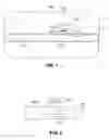
FIG. 4 shows a side view of another embodiment of the subject invention. FIG. 4a shows a first position wherein a platform embodiment is in a retracted state and FIG. 4b shows a position wherein the platform embodiment is in a raised state. The platform is equipped with a vibrating device.
FIG. 5 shows a flow diagram representing a method embodiment of the subject invention.
DETAILED DESCRIPTIONThe subject invention is based on the inventors' discovery that the use of controlled vibration during reflow mechanically assists in the oxide separation commonly formed on solder balls interposed between a substrate and component, and therefore stimulates the complete soldering of the substrate and electrical component. In one embodiment, the subject invention relates to a mechanical or electromechanical device integrated into a reflow oven such that it vibrates the substrate/component combination as it travels on the conveyor, or similar means, for directing a substrate/component through a tunnel of typical reflow ovens. The vibrating device is designed such that it vibrates as the component/substrate combination travels in the heat zone where the solder is molten. Preferably, the vibrating device is capable of adjusting the frequency and amplitude of the vibration as well as withstanding high temperatures.
The vibrating device may take any form of a mechanical or electromechanical device known in the arts to achieve vibration. Examples of suitable vibrating devices that may be used in accordance with the teachings herein include, but are not limited to, gyroscopes, pizeolectric cells, eccentric-cam devices, and oscillating air diaphragm devices. The vibrating should be robust enough to withstand the temperatures produced in reflow ovens to induce molten solder. Alternatively, the vibrating device may be encased in an insulating material to assist the vibrating in withstanding soldering temperatures.
Turning to the figures, FIG. 1 illustrates a schematic of a conventional reflow oven 100 comprising a transfer conveyor 124. The substrate/component combination 115 is put onto the conveyor 124 which directs the substrate/component combination 115 through a tunnel 117 defined in the oven 100 to the heat zone, designated as dash lines 122 of the reflow oven 100. As contemplated herein, the substrate/component combination comprises solder disposed between a substrate and component. With respect to the embodiment shown in FIG. 1, the substrate component combination 115 comprises a substrate 111, solder 113, and a component 114. Typically, the solder is disposed as bumps positioned relative to said substrate and component so as to form a connection between a pad or lead on the component and a pad or lead on the substrate upon melting during the reflow process. Heat is produced by conventional heating device 120 which delivers heat at the heat zone 122. Attached to or integrated with the transfer conveyor 124 is a vibrating device 110. Based on the location of the substrate/component combination 115, or some other conditions such as a predetermined time or temperature, the vibrating device 110 begins vibrating at a controlled frequency and amplitude such that the conveyor 124, and thus the substrate/component combination 115, also vibrate. The vibration caused by the vibrating device 110 is optimized such that upon vibration, the solder balls between the substrate and component collapse thereby forming a robust electrical connection. The vibration acts to mechanically break up oxidation that typically tends to form on the solder, and therefore alleviates the need for utilizing highly reactive and corrosive fluxes with the solder. FIG. 1 shows the vibrating device 110 attached to or integrated with the transfer conveyor 124. The positioning of the vibrating device 110 may vary depending on the optimum placement to effect the collapse of the solder without displacing the substrate and component from each other, which would create other problems. Those skilled in the art, in combination with the teachings herein, would be able to determine optimum placement of the vibrating device on the transfer conveyor.
FIG. 2 shows a carrier embodiment 200 designed for use in connection with conventional chain belt conveyors in reflow ovens. The carrier 200 has disposed within a portion thereof a vibrating device 210. The carrier 200 is designed for carrying substrate/component combinations through reflow ovens in executing the reflow process. The vibrating device may be encased in an insulating material, or alternatively, the carrier 200 may comprise an insulating material that shields the vibrating device 210 from the elevated temperatures in the reflow oven.
FIG. 3 demonstrates the use of the carrier embodiment 200 shown in FIG. 2. The carrier 200 is positioned on the transfer conveyor 124 in the reflow oven 100. The transfer conveyor 124 moves the carrier 200 with a substrate/component combination 215 situated in the carrier through the tunnel 117 of the reflow oven 100. Based on predetermined conditions, such as a predetermined time, location or temperature, the vibrating device 210 attached to or integrated on the carrier 200 begins to vibrate at a controlled frequency and amplitude. This occurs while the substrate/component combination 215 is directed through the heating zone 122 with the heat provided by the heating device 120.
FIGS. 4A and B illustrate another embodiment of the subject invention for vibrating a substrate/component combination 115 during the reflow process. According to this embodiment, a carrier 415 is placed on a transfer conveyor 124 of a reflow oven. A pneumatic platform 435 is mechanically engaged to the transfer conveyor 124 such that the pneumatic platform 435 travels along with the transfer conveyor 124 at the same speed as the conveyor 124. The engagement of the pneumatic platform 435 and the conveyor 124 may take multiple forms such as a conveyor within a conveyor belt pulley system interlinked with the transfer conveyor 124, as is commonly used in industrial/manufacturing processes, or other suitable mechanical means as will be readily appreciated by those skilled in the art. Alternatively, the pneumatic platform 435 may run on a separate track that is designed to run along with the transfer conveyor 124, but is not interlinked to the transfer conveyor 124. At a certain point in the reflow process, the pneumatic platform raises up through an opening (depicted as dashed lines 436) in the carrier 415. The pneumatic arm 435 engages the substrate/component combination 115 and the vibrating device 438 is actuated. As described above, the vibrating device vibrates at a predetermined amplitude and frequency suitable to mechanically break up oxidation on the solder and assist the collapse of the solder balls interposed between the substrate and component. After a predetermined time of vibrating by the vibrating device 438, the pneumatic arm 435 retracts thereby repositioning the substrate/component combination 115 in the carrier 415.
FIG. 5 is a flow diagram according to a method embodiment of the subject invention. In a first step 510 a substrate/component combination is positioned onto a conveyor belt and a reflow oven. As discussed above, substrate/component combination may be placed onto a conveyor belt directly or via a carrier system which engages a conveyor chain belt system. Next the substrate/component combination is directed to a heat zone of the reflow oven (step 512). A vibrating device vibratingly associated with the substrate/component combination is actuated at a predetermined time in the reflow process or a predetermined placement of the substrate/component combination in the reflow oven, or upon a predetermined temperature of the substrate/component combination (step 514). The term vibratingly associated, as used herein, refers to a mechanical association wherein the substrate/component sympathetically responds to the vibration produced by the vibrating device. After the successful soldering of the substrate/component combination takes place, the combination is removed from the reflow oven (step 516).
While the preferred embodiments of the present invention have been shown and described herein in the present context, it will be obvious that such embodiments are provided by way of example only and not of limitation. Numerous variations, changes and substitutions will occur to those of skilled in the art without departing from the invention herein. For example, the present invention need not be limited to best mode disclosed herein, since other applications can equally benefit from the teachings of the present invention. Accordingly, it is intended that the invention be limited only by the spirit and scope of the appended claims.
U.S. Pat. Nos. 5,154,338; and 6,561,407 are cited for background information concerning reflow ovens and the reflow soldering process. These references are incorporated herein in their entirety to the extent they are not inconsistent with the teachings herein.
Claims
What is claimed is:1. A method of forming a solder joint between a substrate and a component comprising solder disposed therebetween, said method comprising;
placing a substrate/component combination into a reflow oven;
directing said substrate/component combination to a heating zone of said reflow oven; and
vibrating said substrate/component combination while said substrate/component combination is in said heating zone, wherein said vibrating occurs at a predetermined amplitude and frequency such that formation of a complete solder joint is encouraged without displacing said substrate and said component relative to each other.
2. The method of claim 1, wherein placing said substrate/component combination into a reflow oven comprises putting said substrate/component combination onto a carrier.
3. The method of claim 2, wherein said carrier is designed to engage a transfer conveyor comprised within said reflow oven.
4. The method of claim 3, wherein said carrier has engaged thereto a vibrating device that vibrates at a predetermined time in the reflow process, or at a predetermined temperature or predetermined position in the reflow oven, or a combination thereof.
5. The method of claim 1, wherein said substrate/component combination comprises interposing solder balls between said substrate and said component.
6. The method of claim 1, wherein said substrate is a printed circuit board.
7. The method of claim 1, wherein said component is a semiconductor device.
8. The method of claim 1, wherein said substrate/component combination is placed onto a transfer conveyor, said transfer conveyor having engaged thereto a vibrating device that vibrates at a predetermined time in the reflow process, or at a predetermined temperature or predetermined position in the reflow oven, or a combination thereof.
9. The method of claim 1, wherein said reflow oven comprises a platform designed for engaging said substrate/component combination, said platform comprising a vibrating device that vibrates at a predetermined time in the reflow process, or at a predetermined temperature or predetermined position in the reflow oven.
10. The method of claim 9, wherein said platform pneumatically engages said substrate/component combination.
11. A carrier designed for positioning onto a transfer conveyor of a reflow oven, said carrier comprising a vibrating device that vibrates at a predetermined time in a reflow process, or a predetermined temperature or predetermined position in the reflow oven.
12. A reflow oven for soldering electrical components to a substrate during a reflow process, said reflow oven comprising:
a tunnel;
a transfer conveyor for directing a substrate/component combination through said tunnel;
a heating zone for generating soldering temperatures at a certain location in said tunnel; and
a vibrating device interlinked to said transfer conveyor, wherein said vibrating device vibrates in said heating zone and vibrates at a predetermined amplitude and frequency such that formation of a complete solder joint is encouraged between said substrate and said component without displacing said substrate and said component relative to each other.
13. A carrier for holding a substrate/component combination during a reflow process, said carrier comprises a vibrating device engaged thereto that vibrates while said substrate/component combination is in said heating zone and vibrates at a predetermined amplitude and frequency such that formation of a complete solder joint is encouraged between said substrate and said component without displacing said substrate and said component relative to each other.
14. A reflow oven for soldering at least one component to a substrate during a reflow process, said reflow oven comprising:
a tunnel;
a transfer conveyor for directing a substrate/component combination through said tunnel;
at least one heating zone for generating soldering temperatures at a certain location in said tunnel; and
a platform designed for engaging said substrate/component combination during said reflow process, said platform comprising a vibrating device engaged thereto that vibrates while said substrate/component combination is in said heating zone and vibrates at a predetermined amplitude and frequency such that formation of a complete solder joint is stimulated between said substrate and said component without displacing said substrate and said component relative to each other.
15. The reflow oven of claim 14, wherein said platform travels in conjunction with said transfer conveyor.
16. The reflow oven of claim 14, wherein said substrate is a printed circuit board.
17. The reflow oven of claim 14, wherein said at least one component is a semiconductor device.
18. The reflow oven of claim 14, wherein said platform pneumatically engages said substrate/component combination.
19. The reflow oven of claim 14, wherein said substrate/component combination travels on said transfer conveyor via a carrier and said platform raises said substrate/component combination from said carrier.
20. In a reflow process for soldering together a substrate/component combination, the improvement comprising vibrating the substrate/component combination during the reflow process.
Images & Drawings included:


Sources:
- United States Patent and Trademark Office - verify current appl. status at the USPTO↗
Recent applications in this class:
- » 20240139847 2024-05-02
BRAZING JOINT, BRAZING METHOD AND DEVICE, FOR PROMOTING SOLDER RHEOLOGY AND GAS OVERFLOW - » 20230278126 2023-09-07
Method and device for liquid spray soldering and the application method thereof - » 20220219254 2022-07-14
METHOD OF CONNECTION TO A CONDUCTIVE MATERIAL - » 20210229203 2021-07-29
Ultrasonic-assisted solder transfer - » 20170274464 2017-09-28
Method for producing a disk with an electrically conductive coating and a metal strip which is soldered onto the disk; and corresponding disk - » 20160256948 2016-09-08
FLUX-LESS DIRECT SOLDERING BY ULTRASONIC SURFACE ACTIVATION - » 20160193678 2016-07-07
Method for ultrasonic welding with particles trapping - » 20150129648 2015-05-14
Method For Minimizing Voids When Soldering Printed Circuit Boards And Soldering Device For Carrying Out Said Method - » 20150008249 2015-01-08
Device for dispensing and distributing flux-free solder on a substrate - » 20100213243 2010-08-26
Transfer device for receiving and transferring a solder ball arrangement
Recent applications for this Assignee:
- » 20140256364 2014-09-11
CORDLESS TELEPHONE ACTIVE-CALL ENABLED INTERCOM - » 20130305129 2013-11-14
Systems and methods for media defect detection - » 20130250745 2013-09-26
Systems and methods for improved servo data operation - » 20130205185 2013-08-08
Systems and methods for low latency media defect detection - » 20130034245 2013-02-07
SPEAKERPHONE USING ADAPTIVE PHASE ROTATION - » 20130024620 2013-01-24
Method and apparatus for adaptive cache frame locking and unlocking - » 20120317456 2012-12-13
Method and apparatus for N+1 packet level mesh protection - » 20120278056 2012-11-01
Characterizing performance of an electronic system - » 20120254679 2012-10-04
Systems and methods for enhanced media defect detection - » 20120250732 2012-10-04
Technique for searching for a preamble signal in a spread spectrum using a fast hadamard transform